
 Product
 Brand
Brand Articles
 Tools
Tools
RB751S40 Single Diode: Datasheet Pdf, Pinout, Application

Schottky Diode Rectifier Small Signal =< 200mA (Io), Any Speed 370mV @ 1mA 150°C Max 500nA @ 30V 2-Termination Tape & Reel (TR) SC-79, SOD-523 Surface Mount
Unit Price: $0.021210
Ext Price: $0.02


Schottky Diode Rectifier Small Signal =< 200mA (Io), Any Speed 370mV @ 1mA 150°C Max 500nA @ 30V 2-Termination Tape & Reel (TR) SC-79, SOD-523 Surface Mount
RB751S40 Single Diode comes from RB751 Series, Planar Schottky barrier single diodes. This article will unlock its pinout, datasheet, feature, application and more details about RB751S40.
RB751S40 Pinout

RB751S40 Pinout
| Pin | Description |
| 1 | CATHODE |
| 2 | ANODE |
RB751S40 Description
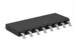
RB751S40 Single Diode comes from RB751 Series, Planar Schottky barrier single diodes with an integrated guard ring for stress protection, encapsulated in small Surface-Mounted Device (SMD) plastic packages.
RB751S40 Feature
■ Low forward voltage
■ Low capacitance
RB751S40 Application
■ Ultra high-speed switching
■ Voltage clamping
■ Line termination
■ Reverse polarity protection
RB751S40 Alternative
The alternative for RB751S40:
RB751S40
RB751V40
Specifications
- TypeParameter
- Factory Lead Time4 Weeks
- Mounting Type
The "Mounting Type" in electronic components refers to the method used to attach or connect a component to a circuit board or other substrate, such as through-hole, surface-mount, or panel mount.
Surface Mount - Package / Case
refers to the protective housing that encases an electronic component, providing mechanical support, electrical connections, and thermal management.
SC-79, SOD-523 - Surface Mount
having leads that are designed to be soldered on the side of a circuit board that the body of the component is mounted on.
YES - Diode Element Material
The parameter "Diode Element Material" refers to the specific semiconductor material used in the construction of a diode. This material determines the electrical characteristics and performance of the diode, including its forward voltage drop, reverse breakdown voltage, and switching speed. Common diode element materials include silicon, germanium, and gallium arsenide, each offering different advantages for various applications. The choice of material impacts the diode's efficiency, thermal stability, and overall suitability for specific electronic circuits.
SILICON - Number of Elements1
- Operating Temperature (Max.)150°C
- Power Dissipation (Max)0.28W
- Packaging
Semiconductor package is a carrier / shell used to contain and cover one or more semiconductor components or integrated circuits. The material of the shell can be metal, plastic, glass or ceramic.
Tape & Reel (TR) - Published2007
- JESD-609 Code
The "JESD-609 Code" in electronic components refers to a standardized marking code that indicates the lead-free solder composition and finish of electronic components for compliance with environmental regulations.
e3 - Part Status
Parts can have many statuses as they progress through the configuration, analysis, review, and approval stages.
Active - Moisture Sensitivity Level (MSL)
Moisture Sensitivity Level (MSL) is a standardized rating that indicates the susceptibility of electronic components, particularly semiconductors, to moisture-induced damage during storage and the soldering process, defining the allowable exposure time to ambient conditions before they require special handling or baking to prevent failures
1 (Unlimited) - Number of Terminations2
- ECCN Code
An ECCN (Export Control Classification Number) is an alphanumeric code used by the U.S. Bureau of Industry and Security to identify and categorize electronic components and other dual-use items that may require an export license based on their technical characteristics and potential for military use.
EAR99 - Terminal Finish
Terminal Finish refers to the surface treatment applied to the terminals or leads of electronic components to enhance their performance and longevity. It can improve solderability, corrosion resistance, and overall reliability of the connection in electronic assemblies. Common finishes include nickel, gold, and tin, each possessing distinct properties suitable for various applications. The choice of terminal finish can significantly impact the durability and effectiveness of electronic devices.
Tin (Sn) - HTS Code
HTS (Harmonized Tariff Schedule) codes are product classification codes between 8-1 digits. The first six digits are an HS code, and the countries of import assign the subsequent digits to provide additional classification. U.S. HTS codes are 1 digits and are administered by the U.S. International Trade Commission.
8541.10.00.70 - Terminal Position
In electronic components, the term "Terminal Position" refers to the physical location of the connection points on the component where external electrical connections can be made. These connection points, known as terminals, are typically used to attach wires, leads, or other components to the main body of the electronic component. The terminal position is important for ensuring proper connectivity and functionality of the component within a circuit. It is often specified in technical datasheets or component specifications to help designers and engineers understand how to properly integrate the component into their circuit designs.
DUAL - Terminal Form
Occurring at or forming the end of a series, succession, or the like; closing; concluding.
FLAT - Peak Reflow Temperature (Cel)
Peak Reflow Temperature (Cel) is a parameter that specifies the maximum temperature at which an electronic component can be exposed during the reflow soldering process. Reflow soldering is a common method used to attach electronic components to a circuit board. The Peak Reflow Temperature is crucial because it ensures that the component is not damaged or degraded during the soldering process. Exceeding the specified Peak Reflow Temperature can lead to issues such as component failure, reduced performance, or even permanent damage to the component. It is important for manufacturers and assemblers to adhere to the recommended Peak Reflow Temperature to ensure the reliability and functionality of the electronic components.
260 - Time@Peak Reflow Temperature-Max (s)
Time@Peak Reflow Temperature-Max (s) refers to the maximum duration that an electronic component can be exposed to the peak reflow temperature during the soldering process, which is crucial for ensuring reliable solder joint formation without damaging the component.
30 - Base Part Number
The "Base Part Number" (BPN) in electronic components serves a similar purpose to the "Base Product Number." It refers to the primary identifier for a component that captures the essential characteristics shared by a group of similar components. The BPN provides a fundamental way to reference a family or series of components without specifying all the variations and specific details.
RB751S40 - Pin Count
a count of all of the component leads (or pins)
2 - Reference Standard
In the context of electronic components, the term "Reference Standard" typically refers to a specific set of guidelines, specifications, or requirements that serve as a benchmark for evaluating the quality, performance, and characteristics of the component. These standards are established by organizations such as the International Electrotechnical Commission (IEC), the Institute of Electrical and Electronics Engineers (IEEE), or specific industry bodies.Reference standards help ensure consistency and interoperability among different components, as they provide a common framework for manufacturers, designers, and users to adhere to. They outline parameters such as electrical properties, mechanical dimensions, environmental conditions, and safety considerations that the component must meet to be considered compliant.By referencing these standards, manufacturers can design and produce components that meet industry-recognized criteria, which in turn helps users select the right components for their applications with confidence. Adhering to reference standards also facilitates regulatory compliance and promotes overall quality and reliability in electronic systems.
IEC-60134 - JESD-30 Code
JESD-30 Code refers to a standardized descriptive designation system established by JEDEC for semiconductor-device packages. This system provides a systematic method for generating designators that convey essential information about the package's physical characteristics, such as size and shape, which aids in component identification and selection. By using JESD-30 codes, manufacturers and engineers can ensure consistency and clarity in the specification of semiconductor packages across various applications and industries.
R-PDSO-F2 - Configuration
The parameter "Configuration" in electronic components refers to the specific arrangement or setup of the components within a circuit or system. It encompasses how individual elements are interconnected and their physical layout. Configuration can affect the functionality, performance, and efficiency of the electronic system, and may influence factors such as signal flow, impedance, and power distribution. Understanding the configuration is essential for design, troubleshooting, and optimizing electronic devices.
SINGLE - Speed
In electronic components, "Speed" typically refers to the rate at which data can be processed or transferred within the component. It is a measure of how quickly the component can perform its functions, such as executing instructions or transmitting signals. Speed is often specified in terms of frequency, such as clock speed in processors or data transfer rate in memory modules. Higher speed components can perform tasks more quickly, leading to improved overall performance in electronic devices. It is an important parameter to consider when designing or selecting electronic components for specific applications.
Small Signal =< 200mA (Io), Any Speed - Diode Type
In electronic components, the parameter "Diode Type" refers to the specific type or configuration of a diode, which is a semiconductor device that allows current to flow in one direction only. There are various types of diodes, each designed for specific applications and functions. Common diode types include rectifier diodes, zener diodes, light-emitting diodes (LEDs), and Schottky diodes, among others. The diode type determines the diode's characteristics, such as forward voltage drop, reverse breakdown voltage, and maximum current rating, making it crucial for selecting the right diode for a particular circuit or application. Understanding the diode type is essential for ensuring proper functionality and performance in electronic circuits.
Schottky - Current - Reverse Leakage @ Vr
Current - Reverse Leakage @ Vr is a parameter that describes the amount of current that flows in the reverse direction through a diode or other semiconductor component when a reverse voltage (Vr) is applied across it. This leakage current is typically very small, but it is important to consider in electronic circuits as it can affect the overall performance and reliability of the component. The reverse leakage current is influenced by factors such as the material properties of the semiconductor, temperature, and the magnitude of the reverse voltage applied. Manufacturers provide this parameter in datasheets to help engineers and designers understand the behavior of the component in reverse bias conditions.
500nA @ 30V - Voltage - Forward (Vf) (Max) @ If
The parameter "Voltage - Forward (Vf) (Max) @ If" refers to the maximum voltage drop across a diode when it is forward-biased and conducting a specified forward current (If). It indicates the maximum potential difference the diode can withstand while allowing current to flow in the forward direction without breaking down. This value is crucial for designing circuits as it helps determine how much voltage will be lost across the diode during operation. Higher Vf values can lead to reduced efficiency in power applications, making this parameter essential for optimizing circuit performance.
370mV @ 1mA - Forward Current
Current which flows upon application of forward voltage.
120mA - Operating Temperature - Junction
Operating Temperature - Junction refers to the maximum temperature at which the junction of an electronic component can safely operate without causing damage or performance degradation. This parameter is crucial for determining the reliability and longevity of the component, as excessive heat can lead to thermal stress and failure. Manufacturers specify the operating temperature range to ensure that the component functions within safe limits under normal operating conditions. It is important for designers and engineers to consider the operating temperature - junction when selecting and using electronic components to prevent overheating and ensure optimal performance.
150°C Max - Output Current-Max
Output Current-Max is a parameter in electronic components that specifies the maximum amount of current that can be safely drawn from the output of the component without causing damage. It is an important specification to consider when designing circuits to ensure that the component can handle the required current without overheating or failing. Exceeding the maximum output current can lead to performance issues, component damage, or even complete failure of the circuit. It is crucial to adhere to the specified maximum output current to ensure the reliable operation of the electronic component and the overall circuit.
0.12A - Voltage - DC Reverse (Vr) (Max)
Voltage - DC Reverse (Vr) (Max) is a parameter in electronic components that specifies the maximum reverse voltage that the component can withstand without breaking down. This parameter is crucial for components like diodes and transistors that are often subjected to reverse voltage during operation. Exceeding the maximum reverse voltage can lead to the component failing or getting damaged. Designers need to consider this parameter when selecting components to ensure the reliability and longevity of their circuits.
40V - Current - Average Rectified (Io)
The parameter "Current - Average Rectified (Io)" in electronic components refers to the average value of the rectified current flowing through the component. This parameter is important in determining the average power dissipation and thermal considerations of the component. It is typically specified in datasheets for diodes, rectifiers, and other components that handle alternating current (AC) and convert it to direct current (DC). Understanding the average rectified current helps in selecting the appropriate component for a given application to ensure reliable operation and prevent overheating.
120mA DC - Rep Pk Reverse Voltage-Max
Rep Pk Reverse Voltage-Max refers to the maximum reverse voltage that an electronic component, such as a diode, can withstand during a specified period of time without failing. This parameter is crucial in determining the safe operating limits of components in circuits where reverse voltage conditions may occur. Exceeding this value can lead to breakdown or permanent damage to the component. It is typically expressed in volts and is a key specification in signal and power applications.
40V - Capacitance @ Vr, F
Capacitance @ Vr, F refers to the capacitance value of a capacitor measured at a specified rated voltage (Vr). It indicates how much electrical charge the capacitor can store per volt when subjected to this voltage. This parameter is essential for understanding the behavior of capacitors in circuits, particularly under different voltage conditions, and ensures that the component operates within its safe limits. The unit of measurement is Farads (F), which quantifies the capacitor's ability to hold an electrical charge.
2pF @ 1V 1MHz - RoHS Status
RoHS means “Restriction of Certain Hazardous Substances” in the “Hazardous Substances Directive” in electrical and electronic equipment.
ROHS3 Compliant
Parts with Similar Specs
- ImagePart NumberManufacturerPackage / CaseCurrent - Average Rectified (Io)RoHS StatusTime@Peak Reflow Temperature-Max (s)Diode TypeNumber of TerminationsTerminal PositionHTS CodeView Compare
![RB751S40,115]()
RB751S40,115
SC-79, SOD-523
120mA (DC)
ROHS3 Compliant
30
Schottky
2
DUAL
8541.10.00.70
![BAT54JFILM]()
SC-76, SOD-323
300mA (DC)
ROHS3 Compliant
30
Schottky
2
DUAL
8541.10.00.70
![BAS70JFILM]()
SC-76, SOD-323
70mA (DC)
ROHS3 Compliant
30
Schottky
2
DUAL
8541.10.00.70


RB751S40 Package

RB751S40 Package
RB751S40 Manufacturer
Nexperia is a dedicated global leader in Discretes, Logic and MOSFETs devices. This new company became independent at the beginning of 2017. Focused on efficiency, Nexperia produces consistently reliable semiconductor components at a high volume: 85 billion annually. The company’s extensive portfolio meets the stringent standards set by the Automotive industry. And industry-leading small packages, produced in their own manufacturing facilities, combine power and thermal efficiency with best-in-class quality levels. Built on over half a century of expertise, Nexperia has 11,000 employees across Asia, Europe and the U.S. supporting customers globally.
Datasheet PDF
- PCN Packaging :
- Datasheets :
- PCN Assembly/Origin :
- RohsStatement :
Trend Analysis
What is the RB751S40 Single Diode from?
RB751 Series.
What is the name of the barrier single diode with an integrated guard ring for stress protection?
Planar Schottky.
When did Nexperia become independent?
2017.
How many semiconductor components does Nexperia produce annually?
85 billion.
What industry standards does Nexperia meet?
Automotive.
 MC33079DG Operational Amplifier: Datasheet, Pinout, Alternatives
03 January 20233543
 TPS61161ADRVR LED Driver: Circuit, Pinout, and Datasheet
20 January 20222448
 TPS51200DRCR Regulator: Features, Applications and Datasheet
28 October 20231664
 BF199 NPN Silicon Transistor, BF199 Datasheet and Equivalents
30 March 20226030
 LT1016 10ns UltraFast Comparator: Datasheet, Pinout, and High-Speed Design Analysis
19 March 2026265
![The Guide to TPS63060DSCR Buck-Boost Switching Regulator IC [FAQ]](https://res.utmel.com/Images/Article/7a961e0a-cdc6-4b9f-8463-ab8d34551a37.jpg) The Guide to TPS63060DSCR Buck-Boost Switching Regulator IC [FAQ]
The Guide to TPS63060DSCR Buck-Boost Switching Regulator IC [FAQ]22 March 20225497
 IRS2092S Audio Amplifier: Schematic, Datasheet Pdf, Typical Application Circuit
09 December 202167942
![How to use TMC2130 Motor Driver IC? [FAQ]](https://res.utmel.com/Images/Article/38cad43a-2bc8-484d-bd1a-a156efda70fb.png) How to use TMC2130 Motor Driver IC? [FAQ]
How to use TMC2130 Motor Driver IC? [FAQ]05 May 20222787
 What is a Microcontroller?
30 October 2025117640
 Voltage Follower: Purpose, Working, and Circuits
27 March 202528425
 What is Feedthrough Capacitor?
06 November 202140921
 A User Guide to Automotive Relay
30 July 20217299
 In Circuit Design, What are the Differences Between the 6 Types of Grounding?
25 March 20245075
 Vision Capabilities Are at the Heart of AI's Evolutionary Possession of Intelligence
06 July 20222278
 FPGA Tutorial: A Beginner's Guide to Programmable Logic Design in 2025
15 April 20254723
 How do Inductors Work?
27 October 202516391
Nexperia USA Inc.
In Stock: 6505
Minimum: 1 Multiples: 1
Qty
Unit Price
Ext Price
1
$0.021210
$0.02
10
$0.020009
$0.20
100
$0.018877
$1.89
500
$0.017808
$8.90
1000
$0.016800
$16.80
Not the price you want? Send RFQ Now and we'll contact you ASAP.
Inquire for More Quantity
![BAT54,215]() BAT54,215
BAT54,215Nexperia USA Inc.
![BAS316,115]() BAS316,115
BAS316,115Nexperia USA Inc.
![BAS21,215]() BAS21,215
BAS21,215Nexperia USA Inc.
![PMLL4148L,115]() PMLL4148L,115
PMLL4148L,115Nexperia USA Inc.
![BAS516,115]() BAS516,115
BAS516,115Nexperia USA Inc.
![BAS16,215]() BAS16,215
BAS16,215Nexperia USA Inc.
![BAT46WJ,115]() BAT46WJ,115
BAT46WJ,115Nexperia USA Inc.
![BAV21,113]() BAV21,113
BAV21,113Nexperia USA Inc.
![BAS321,115]() BAS321,115
BAS321,115Nexperia USA Inc.
![BAS16LD,315]() BAS16LD,315
BAS16LD,315Nexperia USA Inc.


