
 Product
 Brand
Brand Articles
 Tools
Tools
LT1785 RS485 Transceiver Analysis: Managing ±60V Fault Protection and 5V Logic Constraints

Linear Technology/Analog Devices
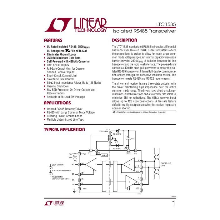
8 Terminations LT1785 Receivers 1 Bits 1/1 Drivers/Receivers 1 Functions


8 Terminations LT1785 Receivers 1 Bits 1/1 Drivers/Receivers 1 Functions
Evaluate the LT1785 RS485 transceiver for industrial networks. Learn how to leverage its ±60V overvoltage protection while addressing 5V supply limitations.
- The ±60V Overvoltage Protection Advantage: Engineering Trade-offs
- Navigating the Disabled Transmitter Leakage Current Anomaly
- The Strict 5V Supply Constraint vs. Modern 3.3V Logic
- Core Specifications at a Glance
- Pin Compatibility and Direct Replacements
- Primary Application Environments
- PCB Layout and Integration Notes
- Hyper-Specific FAQs
- Specifications
- Datasheet PDF
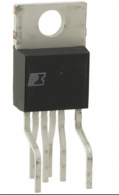
The LT1785 is a half-duplex and full-duplex differential bus transceiver designed for RS485 and RS422 applications featuring on-chip protection from overvoltage faults up to ±60V. Manufactured by Linear Technology (now part of Analog Devices), it is engineered specifically for harsh industrial environments where standard transceivers would be instantly destroyed by miswiring or severe ground potential differences.
When evaluating the LT1785 for a new bill of materials (BOM) or as a replacement for legacy components, engineers must weigh its robust fault tolerance against its specific operational constraints.
Primary Strength: Survives ±60V overvoltage line faults without external protection networks.
Key Limitation: Capped at a 250 kbps data rate due to heavily controlled slew rates.
Supply Requirement: Strict 4.75V to 5.25V operation (not natively compatible with 3.3V logic).
Bus Capacity: High input impedance allows up to 128 nodes on a single bus.
The ±60V Overvoltage Protection Advantage: Engineering Trade-offs
The defining characteristic of the LT1785 is its integrated ±60V overvoltage protection on the interface pins. To understand why this specific value matters, one must look at the environments where RS485 is typically deployed: HVAC controls, factory automation, and SCADA systems.
In these environments, data lines are frequently run in the same conduits or wiring cabinets as 24V AC or 48V DC power lines. A common point of failure occurs during installation or maintenance when a technician accidentally shorts a 24V AC power line to the RS485 data bus. Because 24V AC has a peak voltage of approximately 34V, standard RS485 transceivers (which typically only survive -7V to +12V common-mode voltages) will suffer catastrophic thermal failure, often blowing the IC package apart and potentially damaging the host microcontroller. By offering ±60V protection, the LT1785 absorbs these continuous faults, as well as significant ground shifts, without damage.
However, this level of silicon-level protection introduces a mandatory engineering trade-off: speed for survivability.
To handle extreme overvoltage and control EMI emissions, the LT1785 utilizes heavily controlled slew rates. This limits the maximum data rate to 250 kbps. While 250 kbps is more than adequate for most legacy HVAC protocols (like BACnet MS/TP running at 38.4 kbps or 76.8 kbps) and standard Modbus RTU networks, it becomes a hard bottleneck for high-speed industrial networks requiring 1 Mbps or higher. The controlled slew rate does offer a secondary benefit: it drastically reduces high-frequency EMI emissions and minimizes signal reflection (ringing) on improperly terminated bus stubs, making the network much more forgiving of poor wiring topologies.
Navigating the Disabled Transmitter Leakage Current Anomaly
One of the most critical integration challenges with the LT1785—and a frequent source of troubleshooting headaches—is its behavior when the transmitter is disabled.
When the transceiver is put into a high-impedance receive state (transmitter disabled), an internal current source can pull the -DATA (inverting) pin toward VCC. In a typical RS485 network where the bus is left floating (i.e., all nodes are listening and no one is driving the bus), this leakage current can cause the differential voltage between the +DATA and -DATA lines to drift into an undefined state, or worse, invert completely.
If the -DATA line is pulled higher than the +DATA line by this leakage, the receiver may interpret this as a logical "0" (a start bit). This results in the UART of the host microcontroller receiving framing errors, phantom bytes, or garbage data during idle bus periods.
The Fix: Relying on the transceiver's internal failsafe mechanisms is often insufficient in networks utilizing the LT1785. Engineers must implement external failsafe biasing resistors on the PCB.
1. Place a pull-up resistor (typically 4.7kΩ to 10kΩ) from the +DATA line to VCC.
2. Place a pull-down resistor of the same value from the -DATA line to Ground.
This external bias forces a deterministic idle state (logical "1") across the bus, easily overcoming the internal leakage current. If adding external resistors is impossible due to strict board space or legacy footprint constraints, you will need to consider modern alternatives like the STMicroelectronics ST4E1240DT or the Analog Devices LTC2862, which feature advanced internal failsafe receivers that do not exhibit this specific leakage behavior.
The Strict 5V Supply Constraint vs. Modern 3.3V Logic
The LT1785 operates on a strict supply voltage range of 4.75V to 5.25V. While this was standard when 5V microcontrollers dominated the market, it presents a BOM and layout challenge for modern designs utilizing 3.3V or 1.8V logic.
If you interface a 3.3V microcontroller directly to the LT1785, you face two immediate risks:
VOH (Voltage Output High) Mismatch: The RO (Receiver Output) pin of the LT1785 will drive close to 5V when outputting a logical high. If the host microcontroller's UART RX pin is not 5V-tolerant, this will cause overvoltage damage to the MCU.
VIH (Voltage Input High) Margins: While a 3.3V MCU TX pin might successfully drive the LT1785's DI (Driver Input) pin past its logic-high threshold, the noise margin is severely reduced.
To safely integrate the LT1785 into a 3.3V system, you must add a logic level shifter or utilize a dual-supply isolation IC. This increases component count, consumes PCB real estate, and drives up the total cost of the node. If the ±60V protection is required but the 5V supply is a dealbreaker, upgrading to the LTC2862 is the recommended path. The LTC2862 maintains ±60V fault protection but supports a much wider 3V to 5.5V supply range, allowing direct connection to modern 3.3V microcontrollers without external level shifting.
Core Specifications at a Glance
For rapid qualification, the baseline operating parameters are as follows:
Supply Voltage: 4.75V to 5.25V (Strict 5V domain)
Maximum Data Rate: 250 kbps (Slew-rate limited)
Overvoltage Protection: ±60V (Continuous on bus pins)
ESD Protection: ±15kV on interface pins
Bus Loading: High input impedance supports up to 128 nodes
Protection Features: Short-circuit and thermal shutdown capabilities
Pin Compatibility and Direct Replacements
The LT1785 is designed to be pin-compatible with standard 8-pin RS485 transceivers, making it a viable drop-in upgrade for networks suffering from frequent overvoltage failures.
LTC485 / MAX485 / SN75176: The LT1785 shares the exact same industry-standard 8-pin footprint (RO, RE\, DE, DI, GND, A, B, VCC). You can swap a failed MAX485 with an LT1785 to instantly add ±60V protection, provided the network speed does not exceed 250 kbps.
LTC491: For full-duplex applications (4-wire RS422/RS485), the LT1785 has a 14-pin equivalent that matches the LTC491 footprint.
Texas Instruments SN65HVD1785: This is TI’s direct competitor to the LT1785. It offers similar ±70V fault protection and is explicitly designed to compete in the same harsh-environment sockets.
STMicroelectronics ST485: A standard transceiver that lacks the extreme ±60V protection. Only use this if cost is the primary driver and the wiring environment is strictly controlled.
Primary Application Environments
HVAC Controls: Protecting building automation nodes from accidental 24VAC thermostat wire shorts.
Industrial Control Data Networks: Surviving severe ground loops in factory floors where heavy machinery causes massive ground potential differences.
CAN Bus Applications: Occasionally used as a physical layer driver in custom legacy networks, though standard CAN transceivers are preferred for modern designs.
Supervisory Control and Data Acquisition (SCADA): Long-cable runs across outdoor or electrically noisy environments.
PCB Layout and Integration Notes
Decoupling: Place a 0.1µF ceramic bypass capacitor as close to the VCC and GND pins as physically possible. Because the device handles high transient energies, trace inductance here must be minimized.
Thermal Considerations: While the device features thermal shutdown, continuous short circuits at high voltages will generate significant heat. Since exact thermal derating will depend heavily on your PCB copper area, checking the manufacturer's specific thermal resistance curves is strictly required if you expect sustained faults.
Termination: Standard 120Ω termination resistors should be placed only at the two furthest ends of the bus. Do not place termination resistors at intermediate nodes, as this will overload the LT1785 drivers.
Hyper-Specific FAQs
Why am I seeing false start bits on my UART when the LT1785 transmitter is disabled?This is caused by an internal leakage current pulling the disabled -DATA pin toward VCC, which can cause the differential bus voltage to cross the receiver's threshold and register as a logical "0". You must install external failsafe biasing resistors (pull-up on A, pull-down on B) to hold the bus in a forced logical "1" state during idle periods.
Can I replace a standard MAX485 with the LT1785 without changing the PCB footprint?Yes, the LT1785 is pin-compatible with the MAX485. However, you must verify two things: your network speed must be 250 kbps or lower, and your system must be able to provide a strict 4.75V to 5.25V supply, as the LT1785 does not tolerate supply droop as well as some wider-range transceivers.
Is the LT1785's 250 kbps speed fast enough for a standard DMX512 lighting network?DMX512 operates at exactly 250 kbps. While the LT1785 is rated for this maximum speed, running a component exactly at its absolute maximum data limit across long, heavily loaded cables can reduce timing margins. For DMX512, a slightly faster transceiver (e.g., 500 kbps or 1 Mbps) is generally recommended to ensure sharp edge transitions.
How does the LT1785 handle short-circuit conditions compared to a standard SN75176?A standard SN75176 will attempt to drive maximum current into a short circuit until it overheats and potentially destroys its output stage if the fault voltage exceeds its small common-mode range. The LT1785 features active short-circuit current limiting and thermal shutdown, safely turning off the driver stage before die temperatures reach destructive levels, even if the short is tied to a 60V source.
Watch Tutorial: LT1785
Specifications
Datasheet PDF
- Datasheets :
 TLC555 Timer: Pinout, Package and Datasheet
27 July 20216032
 STP55NF06L Power MOSFET: Pinout, Features, and Datasheet
11 September 20214259
 TOP249YN: Overview, Applications, and Datasheet
27 November 20232812
 Understanding the PIC16F627A/628A/648A Microcontrollers from Microchip
29 February 20241522
 IRFB7545PBF Power MOSFET: IRFB7545PBF MOSFET Equivalent, Datasheet, Pinout
14 January 202213672
 STM32L151RDT7 Microcontroller: Thorough Technical Analysis
29 February 2024135
 TDA1554 Audio Amplifier: Datasheet, Applications and Circuit
27 October 20214907
 A940 PNP Transistor: 2SA940 150V 1.5A Power Transistor, TO-220 and Equivalents
19 January 20227909
 What Makes Tube and Solid-State Audio Amplifiers Different
14 July 20251882
 What are the Differences in the Copying Methods of Double-Sided and Multi-Layer PCBs?
18 July 20224584
 What is VCSEL?
28 October 202111941
 What is a Capacitive Sensor?
31 October 202510998
 Introduction to DDIC (Display Driver IC)
07 January 202633971
 Switching Diodes Basics: Working, Types and Circuit Analysis
24 October 202542727
 What is a Cascode Amplifier?
27 March 202515555
 Substitute Part Validation: How to Cross-Reference and Verify Obsolete Components
04 June 2026205
Linear Technology/Analog Devices
In Stock
United States
China
Canada
Japan
Russia
Germany
United Kingdom
Singapore
Italy
Hong Kong(China)
Taiwan(China)
France
Korea
Mexico
Netherlands
Malaysia
Austria
Spain
Switzerland
Poland
Thailand
Vietnam
India
United Arab Emirates
Afghanistan
Åland Islands
Albania
Algeria
American Samoa
Andorra
Angola
Anguilla
Antigua & Barbuda
Argentina
Armenia
Aruba
Australia
Azerbaijan
Bahamas
Bahrain
Bangladesh
Barbados
Belarus
Belgium
Belize
Benin
Bermuda
Bhutan
Bolivia
Bonaire, Sint Eustatius and Saba
Bosnia & Herzegovina
Botswana
Brazil
British Indian Ocean Territory
British Virgin Islands
Brunei
Bulgaria
Burkina Faso
Burundi
Cabo Verde
Cambodia
Cameroon
Cayman Islands
Central African Republic
Chad
Chile
Christmas Island
Cocos (Keeling) Islands
Colombia
Comoros
Congo
Congo (DRC)
Cook Islands
Costa Rica
Côte d’Ivoire
Croatia
Cuba
Curaçao
Cyprus
Czechia
Denmark
Djibouti
Dominica
Dominican Republic
Ecuador
Egypt
El Salvador
Equatorial Guinea
Eritrea
Estonia
Eswatini
Ethiopia
Falkland Islands
Faroe Islands
Fiji
Finland
French Guiana
French Polynesia
Gabon
Gambia
Georgia
Ghana
Gibraltar
Greece
Greenland
Grenada
Guadeloupe
Guam
Guatemala
Guernsey
Guinea
Guinea-Bissau
Guyana
Haiti
Honduras
Hungary
Iceland
Indonesia
Iran
Iraq
Ireland
Isle of Man
Israel
Jamaica
Jersey
Jordan
Kazakhstan
Kenya
Kiribati
Kosovo
Kuwait
Kyrgyzstan
Laos
Latvia
Lebanon
Lesotho
Liberia
Libya
Liechtenstein
Lithuania
Luxembourg
Macao(China)
Madagascar
Malawi
Maldives
Mali
Malta
Marshall Islands
Martinique
Mauritania
Mauritius
Mayotte
Micronesia
Moldova
Monaco
Mongolia
Montenegro
Montserrat
Morocco
Mozambique
Myanmar
Namibia
Nauru
Nepal
New Caledonia
New Zealand
Nicaragua
Niger
Nigeria
Niue
Norfolk Island
North Korea
North Macedonia
Northern Mariana Islands
Norway
Oman
Pakistan
Palau
Palestinian Authority
Panama
Papua New Guinea
Paraguay
Peru
Philippines
Pitcairn Islands
Portugal
Puerto Rico
Qatar
Réunion
Romania
Rwanda
Samoa
San Marino
São Tomé & Príncipe
Saudi Arabia
Senegal
Serbia
Seychelles
Sierra Leone
Sint Maarten
Slovakia
Slovenia
Solomon Islands
Somalia
South Africa
South Sudan
Sri Lanka
St Helena, Ascension, Tristan da Cunha
St. Barthélemy
St. Kitts & Nevis
St. Lucia
St. Martin
St. Pierre & Miquelon
St. Vincent & Grenadines
Sudan
Suriname
Svalbard & Jan Mayen
Sweden
Syria
Tajikistan
Tanzania
Timor-Leste
Togo
Tokelau
Tonga
Trinidad & Tobago
Tunisia
Turkey
Turkmenistan
Turks & Caicos Islands
Tuvalu
U.S. Outlying Islands
U.S. Virgin Islands
Uganda
Ukraine
Uruguay
Uzbekistan
Vanuatu
Vatican City
Venezuela
Wallis & Futuna
Yemen
Zambia
Zimbabwe
![ADM3232EARUZ]() ADM3232EARUZ
ADM3232EARUZAnalog Devices Inc.
![ADM1485JRZ]() ADM1485JRZ
ADM1485JRZAnalog Devices Inc.
![ADM1486ARZ]() ADM1486ARZ
ADM1486ARZAnalog Devices Inc.
![ADM208AR]() ADM208AR
ADM208ARAnalog Devices Inc.
![ADM3232EARUZ-REEL7]() ADM3232EARUZ-REEL7
ADM3232EARUZ-REEL7Analog Devices Inc.
![ADM3202ARNZ]() ADM3202ARNZ
ADM3202ARNZAnalog Devices Inc.
![ADM101EARMZ-REEL7]() ADM101EARMZ-REEL7
ADM101EARMZ-REEL7Analog Devices Inc.
![ADM485ARZ-REEL]() ADM485ARZ-REEL
ADM485ARZ-REELAnalog Devices Inc.
![ADM3101EACPZ-REEL]() ADM3101EACPZ-REEL
ADM3101EACPZ-REELAnalog Devices Inc.
![ADM485JRZ]() ADM485JRZ
ADM485JRZAnalog Devices Inc.


