
 Product
 Brand
Brand Articles
 Tools
Tools
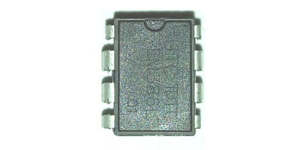
TOP249YN: Overview, Applications, and Datasheet

6 Terminations 6 Pin AC to DC power converter TOPSwitch®-GX Series 1 Outputs 66kHz~132kHz Min 85V V Max 265V V
Unit Price: $1.845254
Ext Price: $1.85


6 Terminations 6 Pin AC to DC power converter TOPSwitch®-GX Series 1 Outputs 66kHz~132kHz Min 85V V Max 265V V
Using the same tried-and-true architecture as TOPSwitch, TOPSwitch-GX integrates fault protection, PWM control, high voltage power MOSFET, and other control circuitry onto a single CMOS chip at a reasonable cost.
TOP249YN Description
Using the same tried-and-true architecture as TOPSwitch, TOPSwitch-GX integrates fault protection, PWM control, high voltage power MOSFET, and other control circuitry onto a single CMOS chip at a reasonable cost. In order to lower system costs and enhance performance, energy efficiency, and design flexibility, numerous new features are integrated. The functions that can be enabled by adding one or three pins above the standard TOPSwitch DRAIN, SOURCE, and CONTROL terminals include line sensing (OV/UV, line feed-forward/DCMAX reduction), precise externally set current limit, remote ON/OFF, synchronization to an external lower frequency, and frequency selection (132 kHz/66 kHz), depending on the type of package.
TOP249YN Pinout

TOP249YN CAD Model
Symbol

Footprint

3D Model

TOP249YN Features
Extended power range for higher power applications
No heatsink required up to 34 W using P/G packages
Features eliminate or reduce cost of external components
Fully integrated soft-start for minimum stress/overshoot
Externally programmable accurate current limit
Specifications
- TypeParameter
- Factory Lead Time6 Weeks
- Mount
In electronic components, the term "Mount" typically refers to the method or process of physically attaching or fixing a component onto a circuit board or other electronic device. This can involve soldering, adhesive bonding, or other techniques to secure the component in place. The mounting process is crucial for ensuring proper electrical connections and mechanical stability within the electronic system. Different components may have specific mounting requirements based on their size, shape, and function, and manufacturers provide guidelines for proper mounting procedures to ensure optimal performance and reliability of the electronic device.
Through Hole - Mounting Type
The "Mounting Type" in electronic components refers to the method used to attach or connect a component to a circuit board or other substrate, such as through-hole, surface-mount, or panel mount.
Through Hole - Package / Case
refers to the protective housing that encases an electronic component, providing mechanical support, electrical connections, and thermal management.
TO-220-7 (Formed Leads), 6 Leads - Number of Pins6
- Weight2.299997g
- Operating Temperature
The operating temperature is the range of ambient temperature within which a power supply, or any other electrical equipment, operate in. This ranges from a minimum operating temperature, to a peak or maximum operating temperature, outside which, the power supply may fail.
-40°C~150°C TJ - Packaging
Semiconductor package is a carrier / shell used to contain and cover one or more semiconductor components or integrated circuits. The material of the shell can be metal, plastic, glass or ceramic.
Tube - Series
In electronic components, the "Series" refers to a group of products that share similar characteristics, designs, or functionalities, often produced by the same manufacturer. These components within a series typically have common specifications but may vary in terms of voltage, power, or packaging to meet different application needs. The series name helps identify and differentiate between various product lines within a manufacturer's catalog.
TOPSwitch®-GX - Published2004
- JESD-609 Code
The "JESD-609 Code" in electronic components refers to a standardized marking code that indicates the lead-free solder composition and finish of electronic components for compliance with environmental regulations.
e3 - Pbfree Code
The "Pbfree Code" parameter in electronic components refers to the code or marking used to indicate that the component is lead-free. Lead (Pb) is a toxic substance that has been widely used in electronic components for many years, but due to environmental concerns, there has been a shift towards lead-free alternatives. The Pbfree Code helps manufacturers and users easily identify components that do not contain lead, ensuring compliance with regulations and promoting environmentally friendly practices. It is important to pay attention to the Pbfree Code when selecting electronic components to ensure they meet the necessary requirements for lead-free applications.
yes - Part Status
Parts can have many statuses as they progress through the configuration, analysis, review, and approval stages.
Not For New Designs - Moisture Sensitivity Level (MSL)
Moisture Sensitivity Level (MSL) is a standardized rating that indicates the susceptibility of electronic components, particularly semiconductors, to moisture-induced damage during storage and the soldering process, defining the allowable exposure time to ambient conditions before they require special handling or baking to prevent failures
1 (Unlimited) - Number of Terminations6
- ECCN Code
An ECCN (Export Control Classification Number) is an alphanumeric code used by the U.S. Bureau of Industry and Security to identify and categorize electronic components and other dual-use items that may require an export license based on their technical characteristics and potential for military use.
EAR99 - Terminal Finish
Terminal Finish refers to the surface treatment applied to the terminals or leads of electronic components to enhance their performance and longevity. It can improve solderability, corrosion resistance, and overall reliability of the connection in electronic assemblies. Common finishes include nickel, gold, and tin, each possessing distinct properties suitable for various applications. The choice of terminal finish can significantly impact the durability and effectiveness of electronic devices.
Matte Tin (Sn) - Max Power Dissipation
The maximum power that the MOSFET can dissipate continuously under the specified thermal conditions.
250W - Terminal Position
In electronic components, the term "Terminal Position" refers to the physical location of the connection points on the component where external electrical connections can be made. These connection points, known as terminals, are typically used to attach wires, leads, or other components to the main body of the electronic component. The terminal position is important for ensuring proper connectivity and functionality of the component within a circuit. It is often specified in technical datasheets or component specifications to help designers and engineers understand how to properly integrate the component into their circuit designs.
ZIG-ZAG - Number of Functions1
- Frequency
In electronic components, the parameter "Frequency" refers to the rate at which a signal oscillates or cycles within a given period of time. It is typically measured in Hertz (Hz) and represents how many times a signal completes a full cycle in one second. Frequency is a crucial aspect in electronic components as it determines the behavior and performance of various devices such as oscillators, filters, and communication systems. Understanding the frequency characteristics of components is essential for designing and analyzing electronic circuits to ensure proper functionality and compatibility with other components in a system.
132kHz - Pin Count
a count of all of the component leads (or pins)
3 - Number of Outputs1
- Output Voltage
Output voltage is a crucial parameter in electronic components that refers to the voltage level produced by the component as a result of its operation. It represents the electrical potential difference between the output terminal of the component and a reference point, typically ground. The output voltage is a key factor in determining the performance and functionality of the component, as it dictates the level of voltage that will be delivered to the connected circuit or load. It is often specified in datasheets and technical specifications to ensure compatibility and proper functioning within a given system.
700V - Output Type
The "Output Type" parameter in electronic components refers to the type of signal or data that is produced by the component as an output. This parameter specifies the nature of the output signal, such as analog or digital, and can also include details about the voltage levels, current levels, frequency, and other characteristics of the output signal. Understanding the output type of a component is crucial for ensuring compatibility with other components in a circuit or system, as well as for determining how the output signal can be utilized or processed further. In summary, the output type parameter provides essential information about the nature of the signal that is generated by the electronic component as its output.
Adjustable - Max Output Current
The maximum current that can be supplied to the load.
8.64A - Analog IC - Other Type
Analog IC - Other Type is a parameter used to categorize electronic components that are integrated circuits (ICs) designed for analog signal processing but do not fall into more specific subcategories such as amplifiers, comparators, or voltage regulators. These ICs may include specialized analog functions such as analog-to-digital converters (ADCs), digital-to-analog converters (DACs), voltage references, or signal conditioning circuits. They are typically used in various applications where precise analog signal processing is required, such as in audio equipment, instrumentation, communication systems, and industrial control systems. Manufacturers provide detailed specifications for these components to help engineers select the most suitable IC for their specific design requirements.
SWITCHING REGULATOR - Operating Supply Current
Operating Supply Current, also known as supply current or quiescent current, is a crucial parameter in electronic components that indicates the amount of current required for the device to operate under normal conditions. It represents the current drawn by the component from the power supply while it is functioning. This parameter is important for determining the power consumption of the component and is typically specified in datasheets to help designers calculate the overall power requirements of their circuits. Understanding the operating supply current is essential for ensuring proper functionality and efficiency of electronic systems.
2.2mA - Output Current
The rated output current is the maximum load current that a power supply can provide at a specified ambient temperature. A power supply can never provide more current that it's rated output current unless there is a fault, such as short circuit at the load.
8.64A - Control Features
Control features in electronic components refer to specific functionalities or characteristics that allow users to manage and regulate the operation of the component. These features are designed to provide users with control over various aspects of the component's performance, such as adjusting settings, monitoring parameters, or enabling specific modes of operation. Control features can include options for input/output configurations, power management, communication protocols, and other settings that help users customize and optimize the component's behavior according to their requirements. Overall, control features play a crucial role in enhancing the flexibility, usability, and performance of electronic components in various applications.
Frequency Control - Topology
In the context of electronic components, "topology" refers to the arrangement or configuration of the components within a circuit or system. It defines how the components are connected to each other and how signals flow between them. The choice of topology can significantly impact the performance, efficiency, and functionality of the electronic system. Common topologies include series, parallel, star, mesh, and hybrid configurations, each with its own advantages and limitations. Designers carefully select the appropriate topology based on the specific requirements of the circuit to achieve the desired performance and functionality.
Flyback - Control Mode
In electronic components, "Control Mode" refers to the method or mode of operation used to regulate or control the behavior of the component. This parameter determines how the component responds to input signals or commands to achieve the desired output. The control mode can vary depending on the specific component and its intended function, such as voltage regulation, current limiting, or frequency modulation. Understanding the control mode of an electronic component is crucial for proper integration and operation within a circuit or system.
VOLTAGE-MODE - Frequency - Switching
"Frequency - Switching" in electronic components refers to the rate at which a device, such as a transistor or switching regulator, turns on and off during operation. This parameter is crucial in determining the efficiency and performance of power converters, oscillators, and other circuits that rely on rapid switching. Higher switching frequencies typically allow for smaller component sizes but may require more advanced design considerations to manage heat and electromagnetic interference.
66kHz~132kHz - Control Technique
In electronic components, "Control Technique" refers to the method or approach used to regulate and manage the operation of the component. This parameter is crucial in determining how the component functions within a circuit or system. Different control techniques can include analog control, digital control, pulse-width modulation (PWM), and various feedback mechanisms. The choice of control technique can impact the performance, efficiency, and overall functionality of the electronic component. It is important to select the appropriate control technique based on the specific requirements and characteristics of the application in which the component will be used.
PULSE WIDTH MODULATION - Switcher Configuration
Switcher Configuration in electronic components refers to the arrangement or setup of a switcher circuit, which is a type of power supply that converts one form of electrical energy into another. The configuration of a switcher circuit includes the specific components used, such as transistors, diodes, capacitors, and inductors, as well as their interconnections and control mechanisms. The switcher configuration determines the efficiency, voltage regulation, and other performance characteristics of the power supply. Different switcher configurations, such as buck, boost, buck-boost, and flyback, are used for various applications depending on the desired output voltage and current requirements. Understanding and selecting the appropriate switcher configuration is crucial in designing reliable and efficient power supply systems for electronic devices.
SINGLE - Internal Switch(s)
The term "Internal Switch(s)" in electronic components typically refers to a built-in mechanism within a device that allows for the control of electrical current flow. These internal switches can be used to turn circuits on or off, change the direction of current, or regulate the flow of electricity within the component. They are often designed to be controlled externally, either manually or automatically, to enable various functions or operations within the electronic device. Internal switches play a crucial role in the overall functionality and performance of electronic components by providing a means to manage and manipulate electrical signals effectively.
Yes - Fault Protection
Protection against electric shock under. single fault conditions.
Current Limiting, Over Temperature, Over Voltage - Max Duty Cycle
Max Duty Cycle refers to the maximum percentage of time that an electronic component, such as a switch or a power supply, can be in an "on" state during a defined time period. It is an important parameter in pulse-width modulated (PWM) systems and helps determine how often a device can operate without overheating or sustaining damage. By specifying the maximum duty cycle, manufacturers provide guidance on the safe operational limits of the component, ensuring reliability and efficiency in various applications.
83 % - Max Supply Voltage (AC)
Max Supply Voltage (AC) refers to the maximum alternating current voltage that an electronic component can safely handle without risk of damage or failure. This parameter ensures the component operates within its designed voltage range and prevents overheating or breakdown. Exceeding the maximum supply voltage can lead to degradation of performance or complete failure of the component. It is crucial for designers to consider this specification when integrating components into electronic circuits to maintain reliability and safety.
265V - Duty Cycle
the percentage of the ratio of pulse duration, or pulse width (PW) to the total period (T) of the waveform.
66.8% - Output Isolation
Output isolation in electronic components refers to the degree to which the output signal is electrically separated or isolated from the input signal or other parts of the circuit. This isolation is important for preventing interference, noise, or voltage fluctuations from affecting the output signal. It helps maintain signal integrity and ensures that the output remains stable and accurate. Output isolation can be achieved through various methods such as using transformers, optocouplers, or isolation amplifiers to physically separate the input and output circuits electrically. This parameter is particularly crucial in applications where there is a need to protect sensitive components or ensure reliable communication between different parts of a system.
Isolated - Min Supply Voltage (AC)
Min Supply Voltage (AC) refers to the minimum alternating current voltage required for an electronic component or device to function properly. It ensures that the device operates within its designed specifications and performance parameters. Operating below this voltage may result in insufficient performance, malfunction, or potential damage to the component. This parameter is critical for ensuring compatibility with power sources and maintaining reliability in electronic applications.
85V - Length10.54mm
- Width4.7mm
- REACH SVHC
The parameter "REACH SVHC" in electronic components refers to the compliance with the Registration, Evaluation, Authorization, and Restriction of Chemicals (REACH) regulation regarding Substances of Very High Concern (SVHC). SVHCs are substances that may have serious effects on human health or the environment, and their use is regulated under REACH to ensure their safe handling and minimize their impact.Manufacturers of electronic components need to declare if their products contain any SVHCs above a certain threshold concentration and provide information on the safe use of these substances. This information allows customers to make informed decisions about the potential risks associated with using the components and take appropriate measures to mitigate any hazards.Ensuring compliance with REACH SVHC requirements is essential for electronics manufacturers to meet regulatory standards, protect human health and the environment, and maintain transparency in their supply chain. It also demonstrates a commitment to sustainability and responsible manufacturing practices in the electronics industry.
No SVHC - Radiation Hardening
Radiation hardening is the process of making electronic components and circuits resistant to damage or malfunction caused by high levels of ionizing radiation, especially for environments in outer space (especially beyond the low Earth orbit), around nuclear reactors and particle accelerators, or during nuclear accidents or nuclear warfare.
No - RoHS Status
RoHS means “Restriction of Certain Hazardous Substances” in the “Hazardous Substances Directive” in electrical and electronic equipment.
RoHS Compliant - Lead Free
Lead Free is a term used to describe electronic components that do not contain lead as part of their composition. Lead is a toxic material that can have harmful effects on human health and the environment, so the electronics industry has been moving towards lead-free components to reduce these risks. Lead-free components are typically made using alternative materials such as silver, copper, and tin. Manufacturers must comply with regulations such as the Restriction of Hazardous Substances (RoHS) directive to ensure that their products are lead-free and environmentally friendly.
Lead Free
Parts with Similar Specs
- ImagePart NumberManufacturerPackage / CaseNumber of PinsNumber of OutputsMax Output CurrentOutput CurrentFrequency - SwitchingOutput VoltageMoisture Sensitivity Level (MSL)View Compare
![TOP249YN]()
TOP249YN
TO-220-7 (Formed Leads), 6 Leads
6
1
8.64 A
8.64 A
66kHz ~ 132kHz
700 V
1 (Unlimited)
![LM2596TVADJG]()
TO-220-5 Formed Leads
5
1
3 A
-
-
5 V
1 (Unlimited)
![FSQ0565RWDTU]()
TO-220-5 Formed Leads
5
1
3 A
-
150kHz
37 V
1 (Unlimited)
![LM2585T-5.0/NOPB]()
TO-220-5 Formed Leads
5
1
-
-
100kHz
5 V
1 (Unlimited)
![LM2587T-5.0/NOPB]()
TO-220-6 Full Pack, Formed Leads
6
1
-
3 A
48kHz ~ 67kHz
12 V
1 (Unlimited)


TOP249YN Package

Datasheet PDF
- Datasheets :
- PCN Assembly/Origin :
What are the key features of TOP249YN?
Some of the prominent features of TOP249YN include primary-side regulation (PSR) control, frequency jittering for reduced EMI, auto-restart protection, thermal shutdown, and energy-efficient operation. It is designed to provide reliable and efficient power conversion in a wide range of applications.
What is the input and output voltage range of TOP249YN?
The TOP249YN IC is designed to handle a wide input voltage range, typically from 85V AC to 265V AC. The output voltage can vary depending on the specific design and application requirements of the SMPS circuit it is used in.
![The Guide to TPS63060DSCR Buck-Boost Switching Regulator IC [FAQ]](https://res.utmel.com/Images/Article/7a961e0a-cdc6-4b9f-8463-ab8d34551a37.jpg) The Guide to TPS63060DSCR Buck-Boost Switching Regulator IC [FAQ]
The Guide to TPS63060DSCR Buck-Boost Switching Regulator IC [FAQ]22 March 20225423
 2N3772 NPN Silicon Transistor: 2N3772 vs. 2N3055, 2N3772 Equivalent, Datasheet PDF
20 January 20225437
 Xilinx XC7A200T-2FBG676C FPGA Overview
06 June 2025431
 Detailed Features and Specifications of STM32F051C8T6
24 July 2025347
 Audio Amplifier IC LM386:Where/How to use?
05 May 202211801
 XCF04SVOG20C: Overview, Features, and Applications
04 December 2023858
 NC7WZ14P6X: Overview, Features, and Applications
06 December 2023374
 SN74LVC1G14DCKR: Overview, Features, and Applications
13 December 2023805
 Memory Chip: The Key to Smart Connectivity
03 November 20212735
![How a CPU is made? [HD Graphics]](https://res.utmel.com/Images/Article/d7470283-3897-4776-abd1-e7eef60aff17.jpg) How a CPU is made? [HD Graphics]
How a CPU is made? [HD Graphics]07 January 202617153
 A Study of the Interelectrode Capacitances of SiC and GaN Power Semiconductor Devices Using Multiple Current Probes
01 February 20232608
 Top 10 Popular Semiconductor Companies in 2025
25 December 202514576
 What is Chiplet?
17 November 20214190
 The Future of Automated and Additive Manufacturing for Power Electronics
24 May 20233428
 The History of Thermometers
15 June 202618681
 What is 4G Router?
27 September 20217529
Power Integrations
In Stock: 28064
Minimum: 1 Multiples: 1
Qty
Unit Price
Ext Price
1
$1.845254
$1.85
10
$1.740806
$17.41
100
$1.642270
$164.23
500
$1.549311
$774.66
1000
$1.461614
$1,461.61
Not the price you want? Send RFQ Now and we'll contact you ASAP.
Inquire for More Quantity


