

 Product
 Brand
Brand Articles
 Tools
Tools
AD5241 Integration Notes: Addressing I2C Failures, Thermal Issues, and Dual-Supply Trade-offs


14 Terminations 2.5V 14 Pin AD5241 Digital Potentiometers I2C 256 Positions
Discover integration notes for the AD5241 I2C digital potentiometer. Learn to resolve No ACK errors, manage dual-supply designs, and select replacements.
- Core Architecture and Key Specifications
- Deep Dive: Resolving I2C "No ACK" and Communication Failures
- The Thermal Trap: Why the AD5241 Gets Hot
- Understanding the Unpowered Resistance Measurement Trap
- Single vs. Dual Supply Operation Trade-offs
- Primary Applications
- Competitors, Equivalents, and Sourcing Alternatives
- Specific Engineering FAQ
- Specifications
- Parts with Similar Specs
- Datasheet PDF
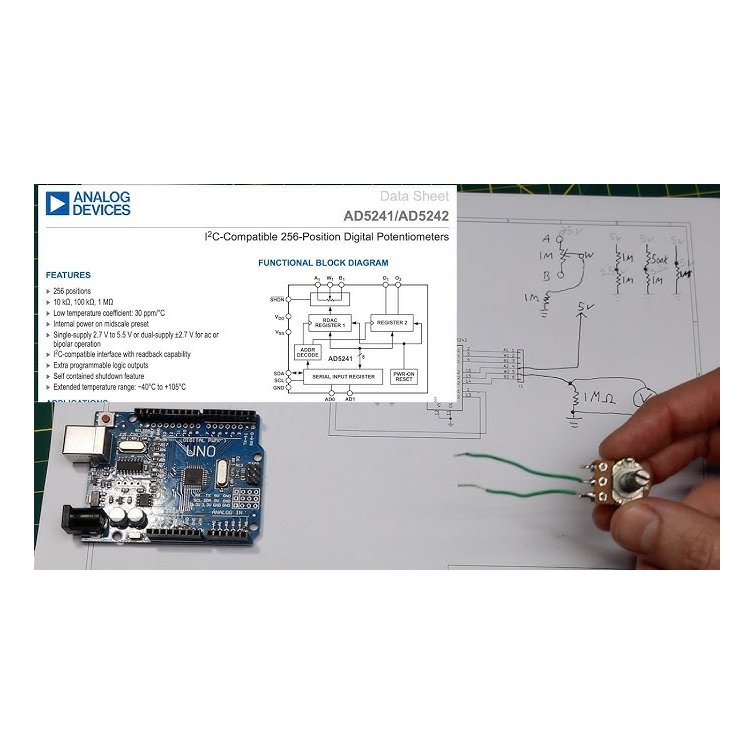
The AD5241 is a single-channel, 256-position digital potentiometer designed for performing the same electronic adjustment function as a mechanical potentiometer, trimmer, or variable resistor.
While digital potentiometers (digipots) have largely replaced their mechanical counterparts in modern automated designs, they introduce a unique set of digital and analog integration challenges. For design engineers and procurement managers evaluating the AD5241 from Analog Devices, success relies on understanding its specific I2C quirks, power-up states, and supply configurations.
This guide breaks down the core operational parameters of the AD5241, with a heavy focus on the most common engineering hurdles: communication failures, unexpected thermal behavior, and the realities of cross-referencing alternative parts.
Core Architecture and Key Specifications
Before diving into integration challenges, it is helpful to establish the baseline capabilities of the AD5241.
Resolution: 256 positions (8-bit).
End-to-End Resistance Options: 10 kΩ, 100 kΩ, and 1 MΩ.
Temperature Coefficient: 30 ppm/°C.
Supply Voltage: 2.7 V to 5.5 V (Single Supply) or ±2.7 V (Dual Supply).
Operating Temperature: -40°C to +105°C.
Interface: I2C-compatible (up to 400 kHz) with readback capability.
Additional Features: Internal power-on midscale preset, extra programmable logic outputs, and a self-contained shutdown feature.
While a 30 ppm/°C temperature coefficient is excellent for a digital potentiometer, engineers must remember that this applies to the end-to-end resistance. When used ratiometrically (as a voltage divider), the tempco matching between internal resistors is typically much tighter, making it highly stable over its -40°C to +105°C range.
Deep Dive: Resolving I2C "No ACK" and Communication Failures
The most frequent issue encountered when bringing up an AD5241 on a new PCBA is an I2C communication failure, specifically the device failing to send an Acknowledge (ACK) bit during bus transfers.
Unlike simple analog components, the AD5241 requires strict adherence to I2C protocol timing and addressing. If your microcontroller is receiving a NACK, the root cause almost always falls into one of three categories:
1. Address Bit-Shifting ErrorsThe AD5241 uses a 7-bit I2C address. A classic trap for firmware engineers is confusing the 7-bit address with the 8-bit shifted address (which includes the Read/Write bit). You must verify how your specific MCU's I2C hardware abstraction layer (HAL) expects the address to be formatted. If the HAL expects an 8-bit value, you must shift the 7-bit address left by one.
2. Floating Hardware Address Pins (AD0 / AD1)The AD5241 allows multiple devices on the same bus by configuring the AD0 and AD1 pins. If these pins are left floating, the device's I2C address will randomly drift based on ambient EMI or adjacent trace coupling. The device might ACK on one power cycle and fail on the next. Both AD0 and AD1 must be hard-tied to solid logic levels (Vdd or Vss).
3. Inadequate Pull-up ResistorsI2C is an open-drain bus. If the SDA or SCL lines lack pull-up resistors, or if the resistors are too weak (e.g., 100 kΩ) for the bus capacitance, the rising edges of the clock/data signals will be too slow. The AD5241 expects crisp edges up to 400 kHz. Standard 4.7 kΩ pull-ups are a safe starting point, but heavily loaded buses may require dropping to 2.2 kΩ.
The Thermal Trap: Why the AD5241 Gets Hot
A digital potentiometer is a low-power CMOS device. Under normal conditions, it should not generate noticeable heat. If the AD5241 is physically hot to the touch, it is almost certainly experiencing shoot-through current in its digital input buffers.
This is a notorious issue when digital inputs (like the address pins, shutdown pin, or unused logic pins) are left floating or driven with intermediate voltages. In a CMOS input stage, an intermediate voltage (e.g., 1.5 V on a 5 V supply) can cause both the internal PMOS and NMOS transistors to turn on simultaneously. This creates a direct, low-impedance path from Vdd to ground, causing excessive current draw and rapid heating.
The Engineering Fix: Audit your schematic. Ensure absolutely every digital input is driven to a valid, solid logic HIGH or LOW. Do not rely on internal weak pull-ups unless explicitly guaranteed by the logic state table. Since exact thermal derating depends heavily on your PCB copper area, checking the manufacturer's specific curves is strictly required here if you are operating near the 105°C ambient limit.
Understanding the Unpowered Resistance Measurement Trap
Technicians and junior engineers often try to verify the AD5241's resistance by probing the W (Wiper), A, and B terminals with a digital multimeter (DMM) while the board is unpowered. This will result in highly erratic, incorrect readings.
A mechanical potentiometer is a passive chunk of carbon or cermet; a digital potentiometer is an array of active CMOS transmission gates (FETs). When the AD5241 is unpowered, these FET channels are not biased. Furthermore, the DMM's injection current will forward-bias the internal ESD protection diodes, giving garbage readings that make the IC appear defective.
Resistance must only be measured while the device is actively powered on. Additionally, note that the AD5241 features an internal power-on reset (POR) circuit that forces the wiper to midscale (position 128) upon power-up. If you probe a 100 kΩ AD5241 immediately after applying power, you will measure approximately 50 kΩ between the wiper and either terminal.
Single vs. Dual Supply Operation Trade-offs
The AD5241 offers the flexibility of single-supply (2.7 V to 5.5 V) or dual-supply (±2.7 V) operation. Choosing between them dictates how you handle analog signals.
Single Supply (Vdd = 5V, Vss = GND):This is the most common and cost-effective configuration. However, the analog signal passing through the A, B, and W terminals cannot drop below ground. If you are processing AC audio signals, you must DC-bias the signal to Vdd/2 to prevent clipping the negative half of the waveform.
Dual Supply (Vdd = +2.7V, Vss = -2.7V):If your application involves true bipolar signals (common in industrial instrumentation, audio processing, and op-amp gain stages), dual-supply operation allows the analog signal to swing above and below ground. The engineering trade-off is BOM complexity: you must provide a clean negative rail, often requiring a charge pump or an inverting switching regulator, which introduces potential switching noise into the sensitive analog path.
Primary Applications
Because of its I2C interface and 256-step resolution, the AD5241 is typically deployed in:
Mechanical potentiometer replacement (for automated calibration).
Instrumentation: Programmable gain amplifiers (PGAs) and offset adjustment.
Multimedia and Audio: Volume control and tone shaping.
Line impedance matching in communications equipment.
Programmable voltage-to-current conversion.
Competitors, Equivalents, and Sourcing Alternatives
When supply chain constraints force a redesign, finding a drop-in replacement for a digital potentiometer is notoriously difficult. Pinouts, package sizes, and digital interfaces vary wildly between manufacturers.
If you are looking at alternatives to the AD5241, consider the following constraints:
Microchip MCP4131 / MCP41 series: A highly popular alternative, but it uses an SPI interface, not I2C. This requires a complete firmware rewrite and PCB layout change.
Texas Instruments TPL0401 / TPL0501: These are I2C-compatible, but the TPL0401 is a 128-position device (7-bit resolution). If your control loop requires 256 steps, this will degrade your adjustment granularity.
Maxim Integrated MAX5403 / MAX5481: Excellent thermal and noise specs, but again, primarily SPI-driven in this class.
Renesas (Intersil) X9C103S: Uses a simple 3-wire Up/Down interface rather than I2C. Great for simple designs, but lacks the specific addressability and readback of the AD5241.
Procurement Note: There is no perfect, universal drop-in replacement for the AD5241. Any swap will require, at minimum, a firmware update to handle different I2C register maps, and likely a footprint spin. Ensure your BOM strategy accounts for this by qualifying multiple I2C digipots early in the design phase if high-volume production is anticipated.
Specific Engineering FAQ
Why does the AD5241 default to midscale on power-up instead of zero?The internal power-on reset (POR) circuit is hardwired to load position 128 into the RDAC register. This is an intentional safety feature for audio and op-amp applications, ensuring that a gain stage doesn't power up into an open-loop (infinite gain) or dead-short state before the microcontroller has time to boot and send I2C commands.
Can I pass currents higher than the datasheet rating if I use a heat sink?No. The current limitation in a digital potentiometer is not purely thermal; it is limited by the current density limits of the internal microscopic CMOS switches (transmission gates). Pushing excessive current through the W terminal will cause electromigration, permanently destroying the internal FETs, regardless of external package cooling.
Why is my programmed resistance slightly different from my measured resistance?Digital potentiometers have a "wiper resistance" (typically 50 Ω to 100 Ω) created by the internal FET switches. If you program a 10 kΩ device to position 0, you will not measure 0 Ω; you will measure the wiper resistance. This must be accounted for in precision op-amp gain equations.
Can I replace the AD5241 with an MCP4131 without changing the PCB?Absolutely not. The MCP4131 utilizes an SPI bus (CS, SCK, SDI/SDO), whereas the AD5241 utilizes I2C (SDA, SCL). The pin definitions, communication protocols, and required firmware drivers are completely incompatible without a board revision.
Watch Tutorial: AD5241
Specifications
Parts with Similar Specs
- ImagePart NumberManufacturerPackage / CaseNumber of PinsResistanceNumber of TapsToleranceTemperature CoefficientMemory TypeInterfaceMin Dual Supply VoltageSupply VoltageView Compare
![AD5241BRU100-REEL7]()
AD5241BRU100-REEL7
14-TSSOP (0.173, 4.40mm Width)
14
100 kΩ
256
-30%, +50%
30 ppm/°C
Volatile
I2C
2.3 V
2.5 V
![MAX5389NAUD T]()
14-TSSOP (0.173, 4.40mm Width)
14
100 kΩ
256
±25%
35 ppm/°C
Volatile
I2C
-
5 V
![MAX5389NAUD]()
14-TSSOP (0.173, 4.40mm Width)
14
100 kΩ
256
±25%
35 ppm/°C
Volatile
Up/Down (U/D, CS)
-
5 V
![MAX5387NAUD]()
14-TSSOP (0.173, 4.40mm Width)
14
100 kΩ
256
±25%
35 ppm/°C
Volatile
Up/Down (U/D, CS)
-
-


Datasheet PDF
- Datasheets :
- ConflictMineralStatement :
 LT1028 0.85nV/√Hz Ultra-Low Noise Op-Amp: Performance Analysis, Pinout, and Stability Guide
12 February 20261128
 Arduino Uno R4 Minima Microcontroller: Descritpion, Features and FAQs
06 October 202310443
 LM2900 Operational Amplifier: Datasheet, Equivalent, Pinout
11 October 20212366
![SN74HC00N IC GATE NAND 4CH 2-INP 14DIP[Video]: Datasheet, Pinout, and Equivalents](https://res.utmel.com/Images/Article/6db9b92c-ecea-4b5a-9210-6814abb3eb0f.jpg) SN74HC00N IC GATE NAND 4CH 2-INP 14DIP[Video]: Datasheet, Pinout, and Equivalents
SN74HC00N IC GATE NAND 4CH 2-INP 14DIP[Video]: Datasheet, Pinout, and Equivalents12 March 20223683
 IS181 Optocoupler: Datasheet, Pinout and Applications
29 July 20212844
 ATMEGA2560 Microcontroller: Pinout, Datasheet and Schematic
13 July 202115228
 2SA1943 PNP Transistor: Datasheet, Price and Equivalent
15 October 202119509
![An Overview of TPS43337QDAPRQ1[FAQ]](https://res.utmel.com/Images/Article/37398212-5ede-448a-811a-c207d6fc744e.jpg) An Overview of TPS43337QDAPRQ1[FAQ]
An Overview of TPS43337QDAPRQ1[FAQ]31 March 2022359
 What are the Different Types of Fingerprint Sensors?
16 December 202010183
 STM32U5: The Most Complex Low-power MCU
19 January 202213193
 What is Cloud Storage?
07 October 20211907
 QUIC: The Next Generation Communication Protocol
22 February 20222070
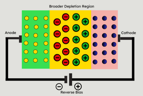 Understanding Photodiodes: Working Principles and Applications - Part 1
08 July 20244595
 How does an Inverter Work?
06 April 202110382
 The Impact of SMPS on LED Lighting and Diverse Industries
05 June 20252736
 Will HBM replace DDR and become Computer Memory?
09 September 202127561
Analog Devices Inc.
In Stock
United States
China
Canada
Japan
Russia
Germany
United Kingdom
Singapore
Italy
Hong Kong(China)
Taiwan(China)
France
Korea
Mexico
Netherlands
Malaysia
Austria
Spain
Switzerland
Poland
Thailand
Vietnam
India
United Arab Emirates
Afghanistan
Åland Islands
Albania
Algeria
American Samoa
Andorra
Angola
Anguilla
Antigua & Barbuda
Argentina
Armenia
Aruba
Australia
Azerbaijan
Bahamas
Bahrain
Bangladesh
Barbados
Belarus
Belgium
Belize
Benin
Bermuda
Bhutan
Bolivia
Bonaire, Sint Eustatius and Saba
Bosnia & Herzegovina
Botswana
Brazil
British Indian Ocean Territory
British Virgin Islands
Brunei
Bulgaria
Burkina Faso
Burundi
Cabo Verde
Cambodia
Cameroon
Cayman Islands
Central African Republic
Chad
Chile
Christmas Island
Cocos (Keeling) Islands
Colombia
Comoros
Congo
Congo (DRC)
Cook Islands
Costa Rica
Côte d’Ivoire
Croatia
Cuba
Curaçao
Cyprus
Czechia
Denmark
Djibouti
Dominica
Dominican Republic
Ecuador
Egypt
El Salvador
Equatorial Guinea
Eritrea
Estonia
Eswatini
Ethiopia
Falkland Islands
Faroe Islands
Fiji
Finland
French Guiana
French Polynesia
Gabon
Gambia
Georgia
Ghana
Gibraltar
Greece
Greenland
Grenada
Guadeloupe
Guam
Guatemala
Guernsey
Guinea
Guinea-Bissau
Guyana
Haiti
Honduras
Hungary
Iceland
Indonesia
Iran
Iraq
Ireland
Isle of Man
Israel
Jamaica
Jersey
Jordan
Kazakhstan
Kenya
Kiribati
Kosovo
Kuwait
Kyrgyzstan
Laos
Latvia
Lebanon
Lesotho
Liberia
Libya
Liechtenstein
Lithuania
Luxembourg
Macao(China)
Madagascar
Malawi
Maldives
Mali
Malta
Marshall Islands
Martinique
Mauritania
Mauritius
Mayotte
Micronesia
Moldova
Monaco
Mongolia
Montenegro
Montserrat
Morocco
Mozambique
Myanmar
Namibia
Nauru
Nepal
New Caledonia
New Zealand
Nicaragua
Niger
Nigeria
Niue
Norfolk Island
North Korea
North Macedonia
Northern Mariana Islands
Norway
Oman
Pakistan
Palau
Palestinian Authority
Panama
Papua New Guinea
Paraguay
Peru
Philippines
Pitcairn Islands
Portugal
Puerto Rico
Qatar
Réunion
Romania
Rwanda
Samoa
San Marino
São Tomé & Príncipe
Saudi Arabia
Senegal
Serbia
Seychelles
Sierra Leone
Sint Maarten
Slovakia
Slovenia
Solomon Islands
Somalia
South Africa
South Sudan
Sri Lanka
St Helena, Ascension, Tristan da Cunha
St. Barthélemy
St. Kitts & Nevis
St. Lucia
St. Martin
St. Pierre & Miquelon
St. Vincent & Grenadines
Sudan
Suriname
Svalbard & Jan Mayen
Sweden
Syria
Tajikistan
Tanzania
Timor-Leste
Togo
Tokelau
Tonga
Trinidad & Tobago
Tunisia
Turkey
Turkmenistan
Turks & Caicos Islands
Tuvalu
U.S. Outlying Islands
U.S. Virgin Islands
Uganda
Ukraine
Uruguay
Uzbekistan
Vanuatu
Vatican City
Venezuela
Wallis & Futuna
Yemen
Zambia
Zimbabwe
![AD5220BRZ10]() AD5220BRZ10
AD5220BRZ10Analog Devices Inc.
![AD5160BRJZ10-RL7]() AD5160BRJZ10-RL7
AD5160BRJZ10-RL7Analog Devices Inc.
![AD5243BRMZ10]() AD5243BRMZ10
AD5243BRMZ10Analog Devices Inc.
![AD5245BRJZ10-RL7]() AD5245BRJZ10-RL7
AD5245BRJZ10-RL7Analog Devices Inc.
![AD5162BRMZ2.5]() AD5162BRMZ2.5
AD5162BRMZ2.5Analog Devices Inc.
![AD5245BRJZ50-R2]() AD5245BRJZ50-R2
AD5245BRJZ50-R2Analog Devices Inc.
![AD5241BRUZ100]() AD5241BRUZ100
AD5241BRUZ100Analog Devices Inc.
![AD5220BRMZ100]() AD5220BRMZ100
AD5220BRMZ100Analog Devices Inc.
![AD5220BRZ100]() AD5220BRZ100
AD5220BRZ100Analog Devices Inc.
![AD5245BRJZ50-RL7]() AD5245BRJZ50-RL7
AD5245BRJZ50-RL7Analog Devices Inc.


