How to Properly Install TVS Diodes in Your PCB Design
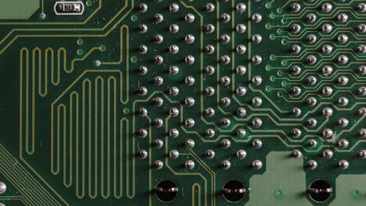
You can install TVS diodes for circuit protection by first identifying where ESD may enter your PCB. Choose the right diode for your signal polarity, then place it as close as possible to connectors or exposed conductors. Keep traces short and ensure correct polarity for reliable ESD defense.
Protection Points
ESD Entry Locations
You need to identify where voltage spikes can enter your PCB. These entry points often include places where users connect cables or touch the board. When you find these spots, you can place esd protection diodes to guard against sudden voltage spikes. This step helps you protect sensitive components from damage.
Strategic placement of esd protection diodes at these points prevents failure of sensitive components exposed to voltage spikes.
You can add suppression circuits to keep voltage spikes within safe limits.
Proper esd protection diodes placement supports compliance with certifications like FCC and CE.
Devices become more reliable in environments with frequent voltage spikes.
Fast-response esd protection diodes at entry locations help stop voltage spikes, surges, and switching transients.
Identifying these points also helps you balance noise prevention and esd shielding for your device.
Tip: Always check for any exposed metal or connectors, as these are common paths for voltage spikes.
Board Edge and Connectors
Board edges and connectors face a high risk from voltage spikes. When you handle the board or connect cables, you can introduce static electricity. This static can cause voltage spikes that harm your circuit. Esd protection diodes placed near these areas can stop voltage spikes before they reach sensitive components.
Sensitive device junctions on the board become easy targets for voltage spikes.
Real-world cases show that touching board edges during assembly increases the risk of voltage spikes.
Packaging materials and dry air can make voltage spikes more likely.
Lab tests show that voltage spikes can damage devices even without direct contact.
Adding esd protection diodes and redesigning circuits can lower failure rates.
Using conductive shunts or extra esd protection diodes at board edges and connectors can reduce failures from 30% to about 2%.
You should always place esd protection diodes close to board edges and connectors. This step gives your design the best chance to survive voltage spikes and keeps your sensitive components safe.
TVS Diodes Selection
Voltage Ratings
You need to select tvs diodes with the right voltage ratings to protect your circuit from voltage spikes. If you choose a diode with a clamping voltage that is too high, your sensitive parts may still get damaged. If the clamping voltage is too low, the diode may trigger during normal operation. Always check the stand-off voltage and breakdown voltage. For example, a 24V system often uses a stand-off voltage of 17V and a breakdown voltage of 19V. The clamping voltage should not go above the maximum voltage rating of your downstream components.
Here is a table showing ESD protection voltage thresholds for different device classes:
| ESD Model | Classification | Voltage Threshold Range (Volts) | Notes |
|---|---|---|---|
| Human Body Model (HBM) | 0Z | Less than 50 V | Highest sensitivity |
| HBM | 0A | 50 to less than 125 V | Sensitive devices |
| HBM | 0B | 125 to less than 250 V | Moderate sensitivity |
| HBM | 1A | 250 to less than 500 V | Lower sensitivity |
| Charged Device Model (CDM) | C0A | Less than 125 V | High sensitivity |
| CDM | C0B | 125 to less than 250 V | Moderate sensitivity |
| CDM | C1 | 250 to less than 500 V | Lower sensitivity |
Tip: Always use the worst-case clamping voltage when you design your over-voltage protection circuit. This helps you protect your devices from unexpected voltage spikes.
Application Matching
You must match tvs diodes to your specific application. Unidirectional diodes work well for DC circuits, while bidirectional diodes protect AC or data lines from voltage spikes in both directions. In RF circuits, pick diodes with low capacitance to avoid signal loss. Make sure the peak pulse current rating can handle the largest expected surge. For example, large surge events need careful fuse selection, since polyfuses may not work well above 30V and several amps.
Choose the right type:
Unidirectional: For one-way voltage spikes.
Bidirectional: For two-way voltage spikes.
Check the placement. Place tvs diodes close to connectors or board edges to stop voltage spikes before they reach sensitive parts.
Use wide traces and ground pours to help the diode handle high currents.
Always test the diode before installation. Use a multimeter to check for shorts or open circuits.
TVS diodes act fast to shunt excess current and reset after the event. They work better than varistors or polymer devices for most ESD events. When you select and test the right diode, you improve your circuit’s safety and reliability.
Preparation
Tools Needed
Before you install a new diode, gather the right tools. You want to make sure your work is safe and accurate. Here is a list of tools you should have ready:
ESD-safe work mat and wrist strap
Soldering iron with adjustable temperature
Solder wire and flux
Fine-tip tweezers
Multimeter (with diode test mode)
Magnifying glass or inspection microscope
Solder sucker or desoldering braid
You can check the performance of your tools using simple tests. For example, a multimeter in diode test mode should show a forward voltage drop between 0.5V and 0.7V for a good diode. If you see an open circuit or a very high voltage drop, the diode may be faulty. When you use a curve tracer or a transient voltage suppressor tester, you can measure clamping voltage and response time. These tests help you confirm that your tools and diodes work as expected.
| Test Type | Tool/Method Used | Performance Data / Expected Result |
|---|---|---|
| Forward Bias Testing | Multimeter (diode test mode) | Forward voltage drop between 0.5V and 0.7V; open circuit or high voltage drop indicates fault |
| Reverse Bias Testing | Multimeter | Open circuit or very high resistance (OL) expected; low resistance or short indicates failure |
| Dynamic Testing | Curve tracer or transient voltage suppressor tester | Measures clamping voltage, peak pulse current, and response time under surge conditions; critical for confirming diode effectiveness |
| In-Circuit Testing | Multimeter (with power off) | Resistance measurement; very low reading suggests short circuit; readings may vary due to parallel components |
Safety Steps
You need to follow safety steps to protect yourself and your circuit. Always wear an ESD wrist strap and work on an ESD-safe mat. This prevents static electricity from damaging sensitive parts. Set your soldering iron to the correct temperature. IPC-J-STD-001 recommends using the right solder alloy and keeping the iron at the right heat level for clean joints. Keep your workspace clean and free of clutter.
Here is a table showing important IPC standards that guide safe and reliable PCB work:
| IPC Standard | Focus Area | Numerical Data / Tool Specifications Supported |
|---|---|---|
| IPC-2221 | PCB design rules | Trace widths, spacing, annular ring sizes, conductor thickness, voltage-based clearance tables, CAD tool DRC settings |
| IPC-J-STD-001 | Soldering process requirements | Soldering iron temperature settings, solder alloy compositions, flux types, solder joint quality criteria, ESD prevention |
| IPC-6012 | PCB qualification and performance | Plating thickness, laminate materials, copper foil quality, dimensional tolerances, electrical testing criteria |
| IPC-A-610 | Assembly acceptability and inspection | Visual acceptance criteria for solder joints, component placement tolerances, cleanliness standards |
| IPC-7711/7721 | Rework, modification, and repair procedures | Temperature and handling guidelines for soldering/desoldering, tool specifications for rework stations |
| IPC-7351 | Surface mount design and land pattern standards | Pad dimensions, spacing, footprint density levels, solder fillet geometry |
Tip: Always check your tools and workspace before you install. This helps you avoid mistakes and keeps your circuit safe.
TVS Diodes Placement
Proximity to ESD Points
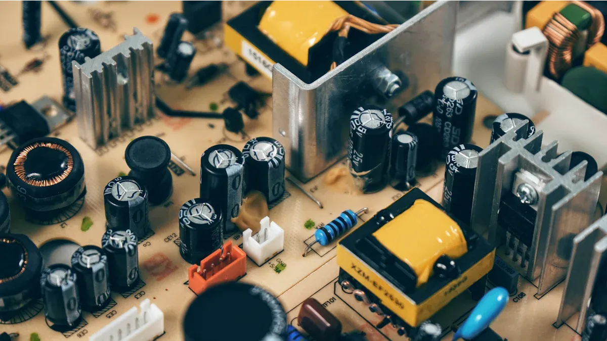
You need to place esd protection diodes as close as possible to where voltage spikes can enter your circuit. These entry points often include connectors, switches, and board edges. When you position tvs diodes near these locations, you give your circuit the best chance to stop voltage spikes before they reach sensitive components.
Placing tvs diodes close to ESD entry points lowers the clamp voltage during an ESD event. This means the diode reacts faster and more effectively, protecting your circuit. Technical studies show that when you reduce the distance between the diode and the entry point, you also reduce the inductance in the trace. Lower inductance helps the diode clamp voltage spikes more efficiently. You can see this improvement in real-world tests, where circuits with nearby diodes show fewer failures and better ESD protection.
Tip: Always check your PCB layout to make sure esd protection diodes sit right next to connectors or exposed metal parts. This simple step can make a big difference in how well your board survives voltage spikes.
Trace Minimization
Short traces matter a lot when you install esd protection diodes. Long traces add unwanted inductance and resistance. These extra elements slow down the response of tvs diodes and can let voltage spikes slip past, putting sensitive components at risk.
When you keep traces short, you improve signal integrity. For example, if you work with a 100MHz signal that has a 3ns rise time, the trace should not be longer than 21cm. If your signal is faster, like 500MHz with a 0.6ns rise time, the trace should be even shorter—about 4cm. Staying within these limits helps you avoid problems like reflections, ringing, and distortion. Your signals stay clean, and your esd protection diodes can react quickly to voltage spikes.
You can follow these best practices to minimize trace length and improve protection:
Place components close together to reduce trace length and lower the risk of EMI.
Use wide traces and ground pours to help esd protection diodes handle high currents from voltage spikes.
Maintain continuous ground planes under signal traces. This gives a stable return path and reduces noise.
Route traces orthogonally and maximize spacing to cut down on crosstalk and coupling.
Choose impedance-controlled tracks for high-frequency signals. This keeps signal quality high and helps tvs diodes work better.
| Best Practice | Benefit |
|---|---|
| Short traces | Faster diode response, less voltage drop |
| Wide traces | Handles higher surge currents |
| Ground pours/planes | Reduces noise, improves ESD shunting |
| Impedance control | Maintains signal integrity |
| Close placement to entry | Lowers clamp voltage, protects components |
Remember: Every millimeter counts. Even a small increase in trace length can weaken your ESD protection and let voltage spikes reach sensitive components.
By following these placement and routing tips, you make sure your esd protection diodes and tvs diodes work at their best. Your circuit will stand up better to voltage spikes and keep sensitive components safe.
Orientation and Soldering
Polarity Check
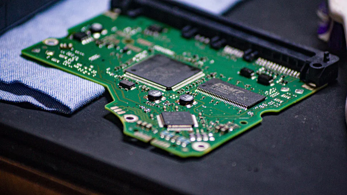
You must always check the polarity before you install tvs diodes. Most tvs diodes have a marking, such as a line or a dot, that shows the cathode side. If you install the diode backward, it will not protect your circuit. In some cases, it may even damage your board. For unidirectional tvs diodes, connect the cathode to the voltage line and the anode to ground. For bidirectional types, you can install them either way, but you should still follow the datasheet.
⚡ Tip: Always double-check the symbol on the PCB and the marking on the diode. Mistakes in polarity are a common cause of ESD protection failure.
Here is a quick reference table:
| Diode Type | Cathode Connection | Anode Connection |
|---|---|---|
| Unidirectional | Voltage line | Ground |
| Bidirectional | Either side | Either side |
Soldering Methods
You need to use the right soldering method to ensure a strong and reliable connection. Start by cleaning the pads and the leads of the tvs diodes. Use a small amount of flux to help the solder flow. Heat the pad and the lead at the same time, then apply solder until it forms a shiny joint. Avoid using too much solder, as this can cause bridges. If you use surface-mount tvs diodes, tweezers help you hold the part in place. For through-hole types, trim the leads after soldering.
Use a soldering iron set to the correct temperature (usually 320–350°C).
Hold the iron on the joint for 1–2 seconds only.
Inspect each joint with a magnifying glass to check for cold solder or bridges.
🔍 Note: Good soldering keeps your ESD protection working. Poor joints can cause your tvs diodes to fail during a voltage spike.
ESD Protection Diodes Testing
Visual Inspection
You should always start by checking your esd protection diodes with a careful visual inspection. This step helps you catch problems before they affect your circuit. Look for any signs of physical damage, such as cracks, chips, or burn marks on the diodes. Check the solder joints to make sure they are shiny and smooth, not dull or cracked. Examine the PCB layers for correct thickness and structure. Make sure the esd protection diodes match the placement and orientation shown in your design.
Follow these steps for a good visual inspection:
Verify that each esd protection diode sits in the correct spot and faces the right direction.
Look for corrosion or dirt on the diode and nearby pads.
Check for missing or extra solder that could cause shorts or open circuits.
Compare your board to industry standards for quality and reliability.
Tip: Automated visual inspection tools can help you find tiny defects that are hard to see with your eyes.
Electrical Testing
After you finish the visual check, you need to test the tvs diode with electrical tools. Use a multimeter to measure voltage and resistance across each esd protection diode. This helps you find open circuits or shorts. For deeper analysis, use an oscilloscope and a signal generator to check how the esd protection diodes respond to voltage spikes.
Key performance metrics show if your esd protection diodes work as expected:
| Metric | Description |
|---|---|
| Breakdown Voltage (VBR) | The voltage where the diode starts to conduct and clamp spikes. |
| Clamping Voltage (Vc) | The voltage the diode holds during a surge to protect your circuit. |
| Peak Current (Ipp) | The highest current the diode can handle during a spike. |
| Reverse Leakage Current (IR) | The small current that flows when the diode is reverse-biased. |
| Capacitance | The stored charge, which can affect high-speed signals. |
You should also check that the response time is fast enough to protect your board. Standards like IEC 61000-4-2 help you know what to expect from your esd protection diodes. Careful testing ensures your circuit stays safe from voltage spikes.
Common Mistakes
Wrong Orientation
You might install tvs diodes in the wrong direction if you do not check the markings. This mistake can stop the diode from protecting your circuit. Always look for the line or dot on the diode. Match it with the symbol on your PCB. If you find a diode facing the wrong way, you should remove it and install it correctly. Wrong orientation often leads to failed ESD protection and can damage your board.
Poor Placement
Placing tvs diodes far from ESD entry points weakens their effect. You should keep these diodes close to connectors or exposed metal. Long traces between the entry point and the diode add resistance and slow down the response. If you spot a poorly placed diode, remove the broken diode and place a new one near the entry point. Good placement helps your circuit survive voltage spikes.
Soldering Issues
Bad soldering can cause tvs diodes to fail. Cold joints, too much solder, or bridges between pads create problems. You need to inspect each joint after soldering. If you see a bad joint, remove the diode, clean the pads, and solder again. Good soldering keeps your ESD protection strong and reliable.
Tip: Careful work during installation helps you avoid these common mistakes and keeps your circuit safe.
You can protect your circuit from voltage spikes by following these steps:
Place tvs diodes close to entry points.
Check orientation before soldering.
Test each diode after installation.
Follow these guidelines to avoid mistakes and keep your PCB safe.
FAQ
How do you know if a TVS diode is working?
Use a multimeter in diode mode. You should see a small voltage drop in one direction. If you see a short or open, replace the diode.
Can you use any TVS diode for any voltage?
No. You must match the TVS diode’s voltage rating to your circuit. Using the wrong rating can cause poor protection or damage.
Where should you place TVS diodes on a PCB?
Place TVS diodes close to connectors or board edges.
Keep traces short.
This helps the diode react quickly to voltage spikes.
 HF PCB Circuit Design 10 QuestionsUTMEL16 March 20223337
Hello everyone, I am Rose. Today I want to give you a full explanation about PCB design. I Hope the following ten questions will give you a satisfied answer.
Read More How Many do You Know About the 12 Components Included in the Circuit Board?UTMEL12 February 20226254
We are lucky to live in an era where electronic devices are readily available. These electronic devices, on the other hand, come to us thanks to the incredible components on the circuit board, and we frequently wonder what makes electronic devices operate, how they achieve such massive success, and how they accomplish it. Electronic devices are incredible things; you can't see what's going on within them, but you can see what they're capable of. We'll talk about the wonders of PCBs and how to get past them to construct the circuit board in this article.
Read More![50 Frequently Asked Questions about PCB Layout [Q&A] 50 Frequently Asked Questions about PCB Layout [Q&A]](https://res.utmel.com/Images/Article/b5ce2a0a-d37c-4243-aff3-df7b2da2db0f.jpg) 50 Frequently Asked Questions about PCB Layout [Q&A]UTMEL16 November 20215025
50 Frequently Asked Questions about PCB Layout [Q&A]UTMEL16 November 20215025In the design of electronic products, PCB layout and routing is an important step, and the quality of PCB layout and routing will directly affect the performance of the circuit.
Read More An Overview of Development BoardUTMEL24 August 202112429
The development board is a circuit board used for embedded system development. Development boards are generally customized by embedded system developers according to development needs.
Read More PCB Design GuidelinesUTMEL21 December 20215220
Hello everyone, I am Rose. Today I will provide you a comprehensive guideline of PCB design.
Read More
Subscribe to Utmel !
![AMSR3-6NZ-O]() AMSR3-6NZ-O
AMSR3-6NZ-Oaimtec
![AM2LS-2424SJZ]() AM2LS-2424SJZ
AM2LS-2424SJZaimtec
![AM10EW-11012DH22-NZ]() AM10EW-11012DH22-NZ
AM10EW-11012DH22-NZaimtec
![JMR0312D15]() JMR0312D15
JMR0312D15XP Power
![JMR0312S05]() JMR0312S05
JMR0312S05XP Power
![JMR0324S05]() JMR0324S05
JMR0324S05XP Power
![AMF18US24]() AMF18US24
AMF18US24XP Power
![AMF18US12]() AMF18US12
AMF18US12XP Power
![AQM200PS24-C2]() AQM200PS24-C2
AQM200PS24-C2XP Power
![AQM300PS48-C2]() AQM300PS48-C2
AQM300PS48-C2XP Power


