Dismantling and Analyzing Each Component in the Switching Power Supply
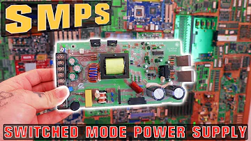
How SMPS works | What Components We Need? Switched Mode Power Supply
The common power supply's function is to convert the input AC mains (AC110V/220V) into several low-voltage DC powers required by the hardware via an isolated switching step-down circuit: 3.3V, 5V, 12V, -12V, and provide the computer with a 5V Standby (5VSB) shutdown for standby. As a result, the power supply is equipped with both high-voltage and high-power components.

The power conversion process is AC input → EMI filter circuit → rectifier circuit → power factor correction circuit (active or passive PFC) → power stage primary side (high voltage side) switching circuit is converted into pulse current → main transformer → power stage secondary side ( Low-voltage side) rectifier circuit → voltage adjustment circuit (such as magnetic amplifier circuit or DC-DC conversion circuit) → filter (smooth output ripple, composed of inductor and capacitor) circuit → power management circuit to monitor the output.
The following is an introduction to the common components of EMI filter circuits at the AC input.
AC input socket
The AC power input from the outside is checked here for the first time. First, to second-order EMI will be fitted at the AC input end to block interference from the power line and prevent switching noise created by the operation of the power supply from spreading out through the power line and interfering with other electrical equipment. (EMI) (Electromagnetic Interference) (EMI) (Electromagnetic Interference) ( The low-pass filter purpose of the filter (filter) is to bypass or steer the high-frequency noise included in alternating current to the ground wire, allowing only the waveform of roughly 60Hz to pass.
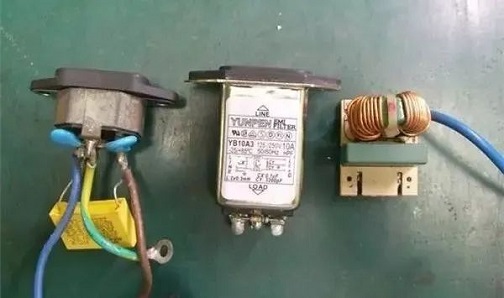
The center one in the above photo is an integrated EMI filter power socket, and the filter circuit is totally contained in an iron box, preventing noise leakage more efficiently. Without a metal enclosure, a power supply with a deep-mounted inbuilt EMI filter will leak some noise, therefore only Cx and Cy capacitors (which will be introduced later) are added to the socket on the left. EMI filter circuits are frequently implemented on the main circuit board. If the EMI circuit area on the main circuit board is empty, the components in that area have been removed. Because the interior area of the power supply with the 12 cm fan is currently insufficient for an integrated EMI filter, the majority of the solutions shown on the left and right sides of the photo are employed.
X capacitor (Cx, also known as cross-line filter capacitor)
The goal of this EMI filter circuit is to reduce low normal noise from the power line by bridging the capacitor between the live wire (L) and the neutral wire (N).
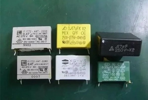
The appearance is square, as indicated in the photo, with the letters X or X2 written on top.
Y capacitor (Cy, also known as line bypass capacitor)
To minimize high normal and common mode noise, the Y capacitor is linked between the floating ground (FG) and the live wire (L)/neutral wire (N).
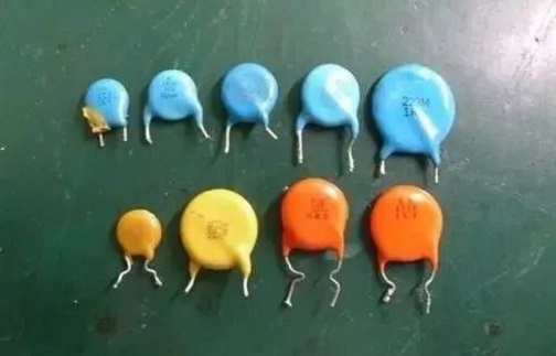
The FG point in the computer power supply is connected with the metal casing, the ground wire (E), and the output terminal 0V/GND in the photo, so when the ground wire is not connected, it will be connected through two series-connected wires. When the human body touches the Cy capacitor, it divides the potential difference (Vin/2) of half of the input power supply, which may induce inductance.
Common mode choke coil (cross-connected inductance)
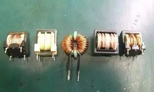
To eliminate the low-pass common mode of the power line and radio frequency noise, the common mode choke coil is connected in series with the live wire (L) and the neutral wire (N) in the filter circuit. Some power supplies' input lines have a design that wraps around the magnetic core and can be thought of as a basic common-mode choke coil. It has a ring and square shape, similar to that of a transformer, and some exposed coils may be seen.
The noise between the L/N line and the ground line E is known as common-state noise, whereas the noise between the L and N lines is known as normal-state noise. The fundamental purpose of the EMI filter is to eliminate and block these two types of noise. The transient protection circuit and the rectifier circuit follow the EMI filter circuit, and the common components are as follows.
Fuse
When the current flowing through the fuse exceeds the rated limit, the fuse will blow, protecting the connection to the back-end circuit. The fuse used in the power supply is usually a fast-blow type, but an explosion-proof kind is preferable. The main difference between this fuse and a standard fuse is that the outer tube is a beige ceramic tube packed with fireproof material to prevent sparks when blown.
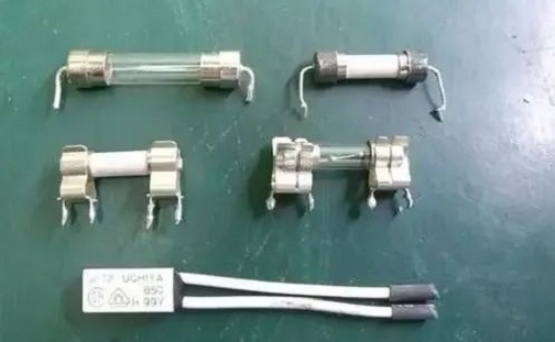
The fixed type at the top of the photo (the two ends are directly covered with wire sockets and soldered to the circuit board) and the detachable type in the middle of the picture are both mounted on the circuit board (fixed with metal clips). A thermal fuse is a square component below. This fuse is attached to the power component's high-power cement resistor or heat sink. It is mostly used for over-temperature prevention to prevent component damage or failure caused by excessive heat. This fuse can also be used in conjunction with a current fuse to provide double protection against both current and temperature.
Negative Temperature Coefficient Resistor (NTC)
The electrolytic capacitor at the high-voltage end of the power supply is in a state of no electricity when the power supply is turned on. Excessive current surge and line voltage drop occur during charging, potentially causing the bridge rectifier and other components to exceed their rated current and burn out. When the NTC is connected in series with the L or N lines, its internal resistance can limit the current during the time of charging, and the negative temperature coefficient means that its resistance decreases as the temperature rises, so when the current runs through the body, the resistance decreases. To reduce unnecessary power usage, the resistance value will progressively decrease as the temperature rises.
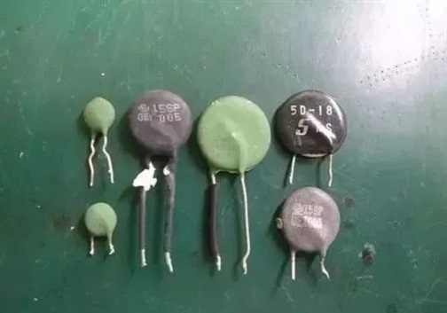
The majority of the components are black and dark green spherical cake-shaped components. However, when the power supply is started in the warm-up state, its protective effect is ignored, and even if the impedance can be reduced with temperature, it still consumes a small amount of power. As a result, the majority of today's high-efficiency power supplies employ more sophisticated instantaneous protection circuits.
Gold Oxygen Varistor (MOV)
At the back of the fuse, the varistor is linked between the live and ground wires. The body shows high impedance when the voltage difference between its two ends is less than its rated voltage value; when the voltage difference exceeds its rated voltage value, the body resistance drops rapidly. There is an estimated short circuit between LN and the front fuse, which will fuse to protect the back-end circuit due to the current created by the short circuit. When the main body is subjected to too much power, it will occasionally self-destruct to alert the user that the device has appeared issue.
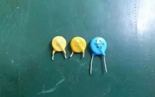
It's commonly found at the power supply's AC input end. The fuse can be blown in time if the input AC overvoltage occurs, preventing harm to the internal components. Its color and appearance are quite similar to Cy capacitors, but the words and models on the components can be differentiated.
Bridge Rectifier
Four diodes are linked alternately in the internal bridge rectifier. Its job is to perform full-wave rectification of the input AC for the switching circuit at the back end.
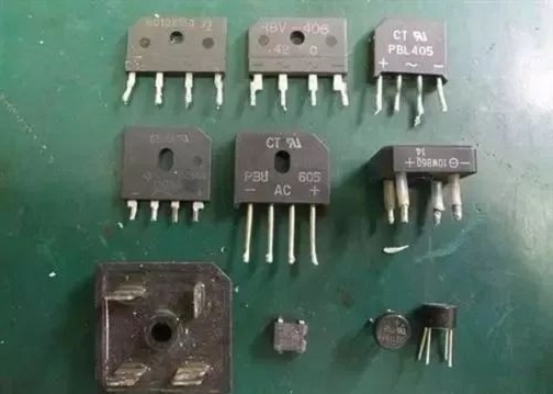
Its look and size will change depending on the components' rated voltage and current. Some power supply will mount it on the heat sink to aid in heat dissipation and ensure long-term stability. It enters the switching circuit on the primary side of the power stage after rectification. The components in this section define the maximum output capability of each channel of the power supply, which is a critical component,
Switching transistor
It is turned on and off according to the control signal to determine whether current flows as a non-contact fast electronic switch in the switching circuit, and it plays a vital role in the active power factor correction circuit and the power stage primary side circuit.
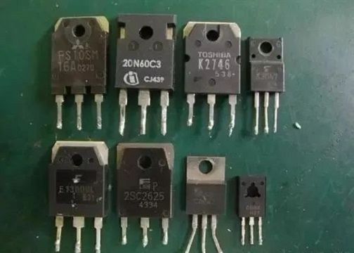
The conventional N MOSFET (N-type metal-oxide-semiconductor field-effect transistor) in the power supply is shown in the upper portion of the photo, while the NPN BJT is shown in the lower section (NPN type double junction transistor). Different power stage topologies, such as dual-crystal forward type, half-bridge type, full-bridge type, push-pull type, and so on, can be produced depending on the circuit composition of the switch components. Switches are also utilized in power supply that requires high efficiency. The synchronous rectifier circuit and the DC-DC step-down circuit are both used with the crystal.
Transformer
Because the transformer is used to separate high and low voltage, and magnetic energy is used for energy exchange, it is called an isolated switching step-down power supply. It can not only avoid leakage danger when the high and low voltage circuit fails, but it can also easily generate a variety of voltage outputs. The transformer's volume is less than that of a standard AC transformer due to its high working frequency.
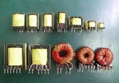
Because the transformer is one of the power transmission pathways, the current large-output power supply has a multi-transformer design to prevent a single transformer from becoming saturated and so limiting the power output. The auxiliary power circuit and the pulse transformer for signal transmission are shown at the top of the shot, while the main power transformer and the annular secondary side adjustment transformer are shown at the bottom.
The output voltage of the secondary side is much lower than that of the primary side when the transformer is used as the isolation boundary, but it still needs to go through rectification, adjustment, filtering, and smoothing circuits, among other things, before it becomes the DC voltage of various voltages required by computer parts.
Diode
Different types and specifications are employed inside the power supply depending on the circuit requirements and output size of each part. There are Schottky barrier diodes (SBD), fast recovery diodes (FRD), and Zener diodes (ZD) in addition to conventional silicon diodes. and so forth.
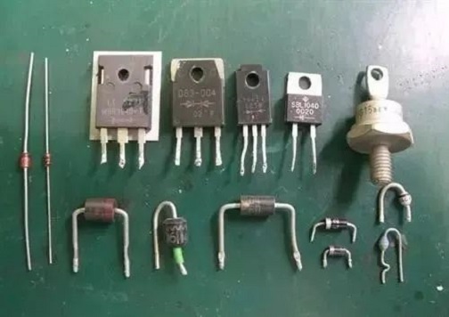
The illustration depicts the most common diode package. SBD is used for the secondary side of the power stage to rectify the transformer output, and ZD is used as a voltage reference. FRD is primarily used for active power factor correction and the primary side circuit of the power stage; SBD is used for the secondary side of the power stage to rectify the transformer output, and ZD is used as a voltage reference.
Inductor
Depending on the structure of the magnetic core, the inductance value, and the installation position on the circuit, inductors can be used as energy storage components in exchange circuits, voltage adjustment components in magnetic amplifier circuits, and output filtering after secondary side rectification. widely employed in
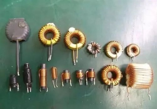
The inductor in the illustration has a ring and cylindrical shape, and the number of turns and thickness of the enameled wire varies depending on the inductance value and current-carrying capability.
Electrolytic capacitors
Capacitors, like inductors, serve as energy storage devices and ripple smoothers. High-voltage electrolytic capacitors are used in the primary side circuit of the power supply to withstand the rectified high-voltage DC; the secondary circuit uses a large number of high-temperature-resistant, long-life, and low-impedance electrolytic capacitors to reduce the loss caused by the continuous charging and discharging of the electrolytic capacitors under the output. capacitance.
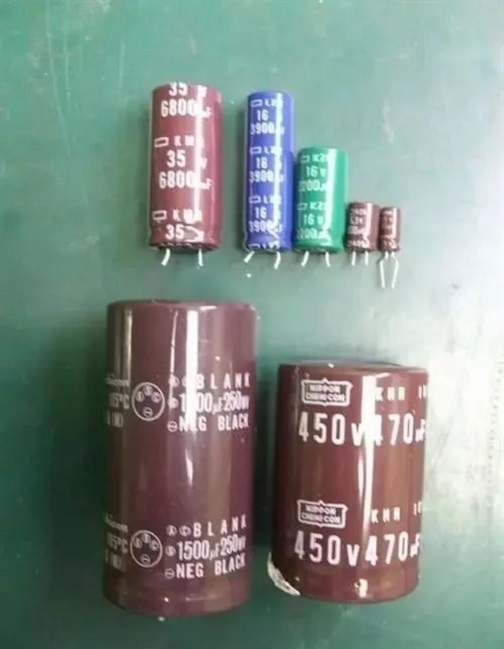
The high voltage electrolytic capacitor in the lower portion of the photo is used for the primary side, while the lower voltage upper part is utilized for the secondary side and the peripheral control circuit. The working temperature has a significant impact on the life of the electrolytic capacitor due to the relationship of chemical substances (electrolytes) in the capacitor. As a result, the brand and series of electrolytic capacitors employed are used for a long period, in addition to maintaining good heat dissipation of the power supply. Determines the power supply's stability and reliability, as well as its lifespan.
Resistor
To avoid electric shock, resistors are employed to limit the current flowing through the circuit and discharge the electric charge stored in the capacitor after the power supply has been turned off.
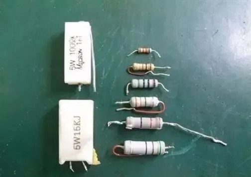
The high-power cement resistor on the left can survive significant power surges, while the common resistor on the right has a color code that indicates its resistance value and inaccuracy. Without a control circuit, the circuit made up of the above components will be unable to perform its job, and each output must be monitored and regulated at all times. To preserve the safety of computer components, the output should be switched off immediately if any irregularity occurs.
Various control ICs
PFC circuits, power stage primary side PWM circuits, PFC/PWM integrated control, integrated components for auxiliary power circuits, and power monitoring and management ICs, for example, are all categorized according to their installation places and applications in the power supply and so on.
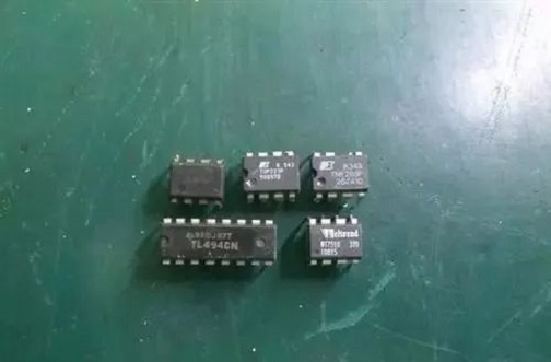
For the PFC circuit, the power supply can maintain a specified power factor and limit the development of high-order harmonics by using active power factor correction circuit regulation. Power stage primary side PWM circuit: as a power stage primary side switching crystal drive with PWM (pulse width modulation) signal generation and duty cycle management of the power output state (Duty Cycle). PWM control ICs, such as the UC3842/3843 series, are common. Integrated PFC/PWM control: By combining the two controllers in a single IC, the circuit can be simplified, the number of components reduced, the volume reduced, and the failure rate reduced. The CM680X series, for example, is a PFC/PWM integrated control IC.
Auxiliary power circuit integrated components: The auxiliary power circuit must continue to output after the power is shut off, so it must be an independent system. Because the output wattage does not need to be too high, the industry's low-power integrated components, such as PI's TOPSwitch series, are used as the core.
Power management and monitoring UVP (low voltage protection), OVP (over-voltage protection), OCP (over current protection), SCP (short circuit protection), and OTP (over-temperature protection) of each output are monitored and protected by the IC. It will close and lock the control circuit after setting the value, stop the power supply's output, and resume it once the fault has been eradicated.
Other ICs, such as fan control ICs, are added by manufacturers when needed in addition to the above components.
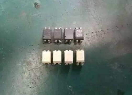
Optocoupler
Optocouplers are primarily used for signal transmission between high-voltage and low-voltage circuits, and they maintain circuit isolation to prevent anomalous current flow between the two circuits in the event of a malfunction, which could harm low-voltage components. The idea is to employ light-emitting diodes and phototransistors to send signals via light, and because there is no circuit connection between them, the circuits at both ends can be kept isolated.
1. Does the switching power supply have a fuse?
The switching power supply generally sets a fuse or a small resistance fuse at the 220V input end.
2. What is the function of the Y capacitor in the switching power supply?
The Y capacitor is used for common mode filtering. It is connected between L to ground or N to ground to filter out the common mode signal of L to ground or N to ground.
, (Y capacitors are usually used symmetrically).
3. What is MOV in switching power supply?
MOV Varistor Varistor is a voltage-limiting protection device. Using the nonlinear characteristics of the varistor, when an overvoltage occurs between the two poles of the varistor, the varistor can clamp the voltage to a relatively fixed voltage value, thereby realizing the protection of the subsequent circuit.
 LLC Converter with Planar Matrix Transformer for High-Current-High-Power ApplicationsSaumitra Jagdale15 March 20242850
The rise of data centres in recent years, driven by cloud computing and big data, has caused a significant increase in electricity consumption. In the United States alone, it exceeded 70 billion kWh by 2014, making up 1.8% of total national electricity usage.
Read More Enhancing Frequency Stability in Modern Distributed Power SystemsRakesh Kumar, Ph.D.21 September 20242499
The article discusses the importance of primary frequency regulation in maintaining grid stability. It also explores battery energy storage systems, virtual synchronous generators, and advanced control strategies to enhance frequency stability in power systems.
Read More The Impact of SMPS on LED Lighting and Diverse IndustriesUTMEL05 June 2025699
Switched-Mode Power Supplies (SMPS) enhance LED lighting and industries by improving energy efficiency, reliability, and sustainability across diverse applications.
Read More What is Uninterruptible Power Supply (UPS)?UTMEL08 April 20214693
UPS is an uninterruptible power supply containing the energy storage device. It is mainly used to give a part of a device with a higher power stability, providing uninterrupted power supplies.
Read More Switch-mode Power Supply BasicsUTMEL14 December 20205917
Switched-mode Power Supply (SMPS), also known as switching converter, is a high-frequency electric energy conversion device and a type of power supply. Its function is to convert a level of voltage into the voltage or current required by the user through different forms of architecture.
Read More
Subscribe to Utmel !
![LY3F-AC120]() LY3F-AC120
LY3F-AC120Omron Automation and Safety
![JW2SN-DC9V]() JW2SN-DC9V
JW2SN-DC9VPanasonic Electric Works
![RGC1A60D60KGE]() RGC1A60D60KGE
RGC1A60D60KGECarlo Gavazzi Inc.
![JQ1P-24V]() JQ1P-24V
JQ1P-24VPanasonic Electric Works
![LY1-DC24]() LY1-DC24
LY1-DC24Omron Automation and Safety
![JVN1AF-12V-F]() JVN1AF-12V-F
JVN1AF-12V-FPanasonic Electric Works
![3RT20161AF01]() 3RT20161AF01
3RT20161AF01Siemens
![ADW1103W]() ADW1103W
ADW1103WPanasonic Electric Works
![3RH21222BM40]() 3RH21222BM40
3RH21222BM40Siemens
![3RT20241DB443MA0]() 3RT20241DB443MA0
3RT20241DB443MA0Siemens


