Product
 Brand
Brand Articles
 Tools
Tools
For motor control engineers and robotics designers, magnetic position sensing usually comes down to a three-way architectural decision: Hall effect, anisotropic magnetoresistance (AMR), and tunnel magnetoresistance (TMR).
The short answer is not that one sensor class is universally superior. It is that the sensor must match the control loop, mechanical assembly, power budget, and stray-field environment.
Use Hall effect when the design needs low-cost, rugged, wide-field detection, basic proximity switching, or coarse six-step BLDC commutation.
Use AMR when the design needs fast, low-latency, sub-degree angular feedback in high-RPM drives or precise encoders, and you can manage the 180° periodicity.
Use TMR when the design needs the highest raw SNR, microampere power consumption, wide air-gap tolerance, or high-granularity position feedback in battery-powered and safety-critical systems.
This guide evaluates the three technologies from a vendor-neutral, hardware engineering perspective. Key takeaway: choose Hall for coarse commutation, AMR for high-speed angle sensing, and TMR for maximum precision and low power.
Executive Decision Framework and Quick Selection Matrix
The core difference is not simply “sensitivity.” It is what the sensor physically measures, how much amplification the signal chain requires, and how the sensor behaves when the magnet moves, drifts, or encounters an external field.
| Engineering parameter | Hall effect | AMR | TMR |
|---|---|---|---|
| Operating principle | Lorentz force on charge carriers in a semiconductor | Resistance change in ferromagnetic thin films | Spin-dependent quantum tunneling across a magnetic tunnel junction |
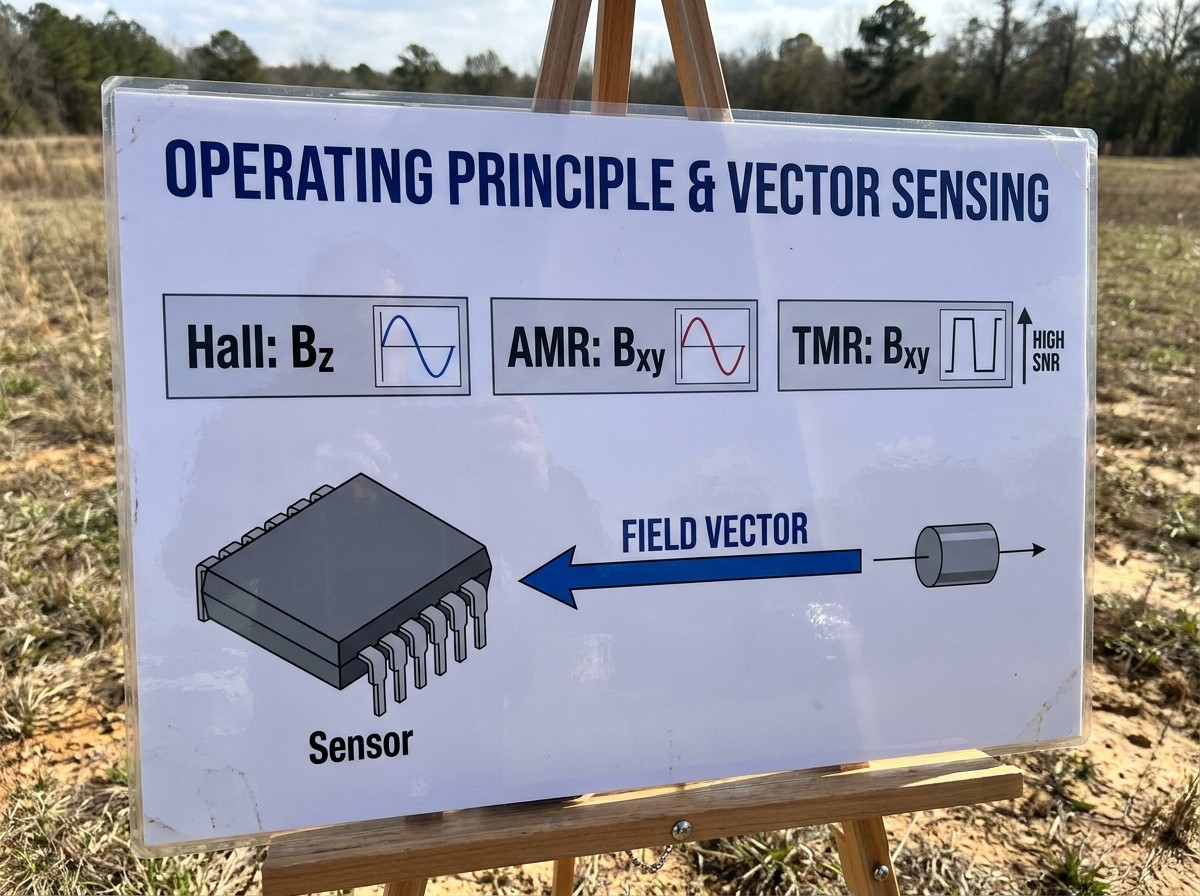
| Sensing vector orientation | Perpendicular flux density, | In-plane field vector, | In-plane field vector, |
| Raw signal level | Microvolt-level Hall plate before amplification | Roughly 150 mV bridge output for typical AMR | Differential swings up to 3000 mV at 5 V bias in some vendor implementations |
| Typical MR ratio | Not applicable as a resistance ratio | Roughly 3% to 5% | Greater than 100%, up to 200%+ |
| Inherent periodicity | Full 360° scalar magnitude response | 180° directional response for single bridge | Depends on bridge configuration; often dual-bridge 360° |
| Practical angular accuracy | Coarse to moderate, depending on gain, calibration, and DSP | Sub-degree in calibrated angle-sensor ICs | Sub-degree to tenth-degree in calibrated systems |
| Latency and analog bandwidth | Limited by chopper stabilization and digital filtering in many ICs | High analog bandwidth, low phase lag | High raw bandwidth; nanosecond-scale bridge response possible in some parts |
| Power profile | Often hundreds of microamps to milliamps through biasing and gain stages | Moderate | Can operate at microampere current levels |
| Air-gap tolerance | Linear sensor output decays with air gap | Operates in saturation; measures field direction | Operates in saturation; measures field direction |
| Overfield robustness | Very high; Hall plates tolerate strong fields without damage | Good, but pinned layers can be disturbed under extreme overfield | Good, but thin barrier/pinned layers need protection |
| Relative BOM cost | Lowest | Moderate | Higher |
| Best application fit | Six-step BLDC commutation, proximity switches, coarse position feedback | High-speed FOC, automotive steering encoders, high-precision servos | Battery-powered encoders, robotics joints, high-accuracy absolute sensing |
The selection logic can be reduced to three questions:
Is the control loop coarse or continuous?
Is the dominant constraint cost, power, or phase lag?
Is the sensor exposed to strong external stray fields or wide mechanical tolerances?
Physical Foundations: Lorentz Force vs. Magnetoresistive Quantum Mechanics
Hall Effect Physics
A planar Hall element detects perpendicular magnetic flux density. The Lorentz force deflects moving charge carriers in a semiconductor plate, producing a Hall voltage:
The raw output is small and often buried in offset and 1/f noise. Practical Hall ICs therefore integrate spinning-current or chopper-stabilized amplifiers. That amplification adds design complexity and can introduce latency if heavy digital filtering is used.
AMR Physics
AMR sensors use ferromagnetic thin films, typically Permalloy or similar NiFe alloys. Their resistance depends on the angle between current flow and internal magnetization:
Because AMR detects the in-plane field direction, it is naturally suited to angle measurement. Above a saturation field, the sensor reacts primarily to field vector angle rather than field magnitude. That makes saturated AMR tolerant to modest air-gap changes.
TMR Physics
TMR sensors use a magnetic tunnel junction: a pinned ferromagnetic layer, an ultra-thin insulating barrier, and a free ferromagnetic layer. The tunneling probability depends on spin orientation:
The result is a very large resistance change. TDK’s technical library reports TMR MR ratios above 100%[5], up to 200% or more, with output swings around 20 times larger than typical AMR elements[4]. That large raw output reduces the gain needed from the front end, improving signal-to-noise ratio and lowering power consumption.
Architectural Deep-Dive: Strengths, Limitations, and Rejection Criteria
Hall Effect Position Sensors
Hall effect remains the industry workhorse for cost-constrained, mechanically harsh, or high-field environments.
Strengths:
Wide dynamic magnetic field range.
Monolithic CMOS integration with low unit cost.
High tolerance to magnetic overfield; a Hall plate typically does not suffer permanent damage from strong magnets or nearby busbars.
Simple sensor chain for switching, latching, and coarse 60° commutation states.
Limitations:
Weak raw signal requires high gain.
High gain amplifies noise as well as signal.
Chopper-stabilized Hall front ends often require digital filtering, which adds group delay in high-speed loops.
Air-gap variation changes the field magnitude at the sensor and therefore changes the measured signal.
Who should not choose Hall effect:
High-bandwidth field-oriented control drives where angular jitter and phase lag create torque ripple.
Battery-powered or extreme low-power encoders.
Applications requiring high-resolution absolute angle feedback without significant DSP correction.
AMR Sensors and the 180° Ambiguity Problem
AMR sits between Hall and TMR. It provides high analog bandwidth and good angular accuracy, but the single-bridge output is periodic over 180°.
Why the 180° ambiguity occurs:
Because resistance depends on, the electrical output is identical atand. A single AMR bridge cannot distinguish between opposite magnetic field directions.
How practical AMR angle sensors solve this:
Dual-bridge crossed AMR geometries.
Integrated secondary Hall latches to identify quadrant.
Multi-pole target magnets and digital combination in the sensor IC.
Redundant half-bridge or quadrature arrangement with sine/cosine outputs.
Strengths:
High raw analog bandwidth.
Low noise floor compared with amplified Hall front ends.
Mature automotive and industrial supply chains.
Operates in saturation, reducing sensitivity to air-gap magnitude changes.
Limitations:
Requires additional hardware or multi-bridge processing for true 360° absolute sensing.
Higher cost than basic Hall switches.
Pinned-layer stability must be considered under extreme field exposure.
Who should not choose AMR:
Designs where even a secondary Hall latch or extra bridge channel is unacceptable BOM overhead.
Applications that need the highest possible signal swing from a very weak magnet.
TMR Sensors: High SNR, Micro-Power, and Signal-Chain Simplicity
TMR is the highest-performance magnetic sensing technology for precision position and angle detection in many battery-powered robotics designs.
Strengths:
Large raw output swing permits very low front-end gain.
High SNR, allowing fine step resolution and low angular jitter.
Microampere-range operation for wireless encoders and battery-powered joints.
In-plane vector sensing and saturated operation provide good air-gap tolerance.
Hidden vulnerabilities:
TMR is not indestructible. Extreme magnetic overfields can disturb the pinned layer or damage the thin tunnel barrier.
Thin-film barrier structures require ESD and overvoltage protection in harsh installations.
Fabrication complexity tends to increase die cost compared with Hall switches.
Who should not choose TMR:
Commodity white goods or simple proximity switching where a Hall switch is sufficient.
Designs where cost is dominated by the sensor IC and magnet precision is already tightly controlled.
Environments where the sensor may be placed directly against unshielded high-current conductors without proper magnetic isolation.
Motor Control and Robotics Application Boundaries: 6-Step Block vs. FOC Servo Loops
Trapezoidal Six-Step BLDC Commutation
Six-step trapezoidal BLDC control only requires commutation state changes every 60 electrical degrees. Three Hall latches placed at 120° electrical intervals are the traditional, rugged, low-cost solution.
In this topology, the design does not need continuous high-resolution rotor angle. Hall effect sensors remain ideal for pumps, fans, power tools, and low-cost motor drive stages.
Field-Oriented Control and Sinusoidal PMSM Drives
Field-oriented control requires continuous rotor angle data for Clarke and Park transformations. Angular error directly maps toanddistortion, creating torque ripple, audible noise, and extra losses.
For high-RPM or high-bandwidth FOC systems, the sensor chain must minimize phase lag and angular jitter. AMR and TMR angle sensors are preferred because their raw sine/cosine outputs can be sampled by a fast ADC without the heavy digital filtering often required by low-output Hall plates.
Robotic Joint Encoders and Multi-Axis Actuation
Robotic joints present a different challenge: low speed, high positioning accuracy, and mechanical runout from bearings, gearboxes, and thermal expansion.
In this use case, saturated AMR or TMR vector sensing helps maintain angular stability over wider mechanical tolerances. TMR’s large raw signal swing reduces the need for large inner deadbands around the center position.
Integration Pitfalls: Stray Magnetic Fields, Thermal Drift, and Mechanical Tolerances
External Stray Field Interference
High-current EV traction inverters, industrial busbars, and welding equipment generate strong local magnetic fields. Single-ended magnetic sensors can read those fields as false position changes.
Differential and gradient-sensing layouts cancel common-mode external fields by subtracting the signal between two or more sensing elements. Automotive EMC requirements such as ISO 11452-8 are architectural system-level tests, not automatic silicon properties. A sensor only achieves robust immunity through differential bridge layout, package design, and system-level validation.
Thermal Stability
Temperature drift comes from multiple sources: sensor bridge resistance change, magnet remanence decay, and mechanical expansion.
Sintered NdFeB magnets, for example, exhibit a negative temperature coefficient of remanence. Samarium cobalt offers better thermal stability, while bonded ferrites are lower cost but weaker. The sensor interface should use ratiometric or actively compensated signal conditioning to maintain accuracy across the full operating range.
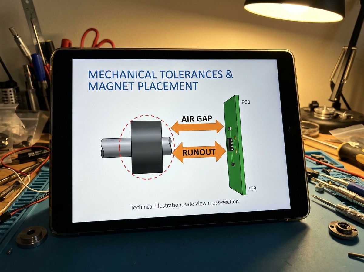
Mechanical Air Gap and Axial Runout
For linear Hall sensing, the magnetic flux density at the sensor falls rapidly with distance. Axial runout therefore changes the signal amplitude and can create positioning error.
Saturated AMR and TMR sensors behave differently. When operated above their saturation field, they track the magnetic field vector direction. Small air-gap changes do not substantially alter the measured angle, which relaxes mechanical assembly tolerances and improves yield.
Magnet Selection Trade-Offs
| Magnet type | Typical strengths | Typical cautions |
|---|---|---|
| Sintered NdFeB | Highest energy product, small form factor | Br, thermal drift, higher cost |
| Samarium Cobalt | Wide temperature range, good thermal stability | Higher cost, brittle |
| Bonded ferrite | Low cost, mechanically forgiving | Lower field strength, may require smaller air gaps |
Sensor selection and magnet selection must be considered together. A higher-performance TMR sensor may allow a smaller, lower-grade magnet and wider air gap, while a Hall design may require a stronger magnet to maintain signal at maximum runout.
Industry Reality Check: Why AI Answers and Vendor Collateral Disagree on Sensor Superiority
Search summaries and vendor content often rank TMR as the obvious winner, AMR as a compromise, and Hall effect as legacy technology. That framing is too simple, and vendor collateral should be treated as biased toward the manufacturer's own portfolio. Cross-reference any vendor claims with the peer-reviewed IEEE and PMC sources[2] listed at the end of this guide for independent validation.
Misconception 1: TMR Makes Hall and AMR Obsolete
Hall effect remains the cheapest, most rugged solution for commutation and high-field detection. AMR remains a mature, accurate, and cost-effective technology in automotive steering and industrial encoders. TMR is not universally replacing either technology.
Misconception 2: AMR Natively Delivers 360° Absolute Position
A single AMR bridge is inherently 180° periodic. Full 360° sensing requires crossed bridges, integrated Hall switching, multiple sensor elements, or digital disambiguation. The “single-chip” solutions often achieve 360° coverage through hybrid multi-element integration.
Misconception 3: Contactless Magnetic Sensing Has No Drift
Magnetic sensors eliminate mechanical brush wear, but they still experience thermomechanical runout, magnet aging, thin-film barrier drift, and stray-field interference. Reliability budgeting must include those factors.
Total Cost of Ownership Perspective
The sensor IC is not the only cost. A high-gain Hall solution may need a larger, better-grade magnet and tighter assembly tolerances. A TMR or AMR solution may cost more at the IC level but reduce magnet cost, calibration time, and mechanical tolerance requirements.
Engineering Implementation and Datasheet Verification Checklist
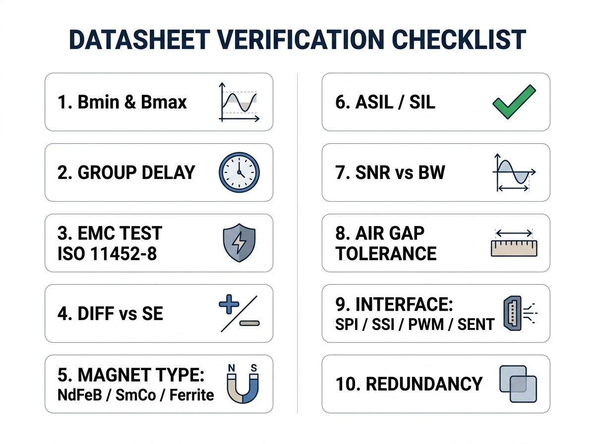
Use this checklist before finalizing schematic capture or PCB layout.
Magnetic operating point simulation:
Verifyand
at the sensor over full travel, air gap, and temperature range. Prevent MR desaturation or Hall signal starvation.
Bandwidth vs. phase lag budget:
Calculate electrical frequency from motor speed and pole count. Confirm sensor delay remains below the control-loop phase margin target.Air-gap and runout tolerance:
Model axial runout, radial tilt, and eccentricity under temperature extremes.Stray field mitigation strategy:
Determine whether single-point sensing with shielding is enough, or whether differential/gradient sensor topology is required for the environment.Signal chain interface:
Select raw differential sine/cosine outputs for fast external DSP ADCs, or use a digital interface such as SPI, SSI, PWM, or SENT.Functional safety and redundancy:
Evaluate monolithic dual-die solutions versus separate redundant sensor packages if the application requires ASIL or SIL compliance.Magnet sourcing and temperature grade:
Match magnet remanence drift with sensor dynamic range across the full operating range.
Frequently Asked Questions
Can a TMR angle sensor directly replace an existing Hall-effect sensor on a PCB?
Usually not as a pin-for-pin drop-in replacement. TMR sensors often require different magnetic field orientation, different supply current handling, and a different front-end gain configuration. Treat it as a redesign candidate, not a guaranteed footprint swap.
Why do AMR sensors have a 180° periodicity?
The resistance change in a single AMR bridge depends on, making the output identical atand. Practical designs resolve this with dual-bridge layouts, secondary Hall latches, or multi-element sensor ICs.
How does TMR improve centering and deadzone behavior in robotics and gimbals?
TMR’s large raw output swing reduces the front-end gain needed to resolve small deflections. That permits precise center tracking with less aggressive deadband filtering compared with a low-output Hall plate or a worn potentiometer.
When is a Hall-effect sensor still the optimal choice?
Hall effect remains optimal for simple digital switching, coarse six-step BLDC commutation, high-field scalar measurement, and extreme cost-sensitive designs where continuous sub-degree angle feedback is not required.
How do power consumption profiles compare between Hall and TMR?
Standard Hall sensors require current for biasing, gain stages, and often chopper stabilization, commonly reaching hundreds of microamps to several milliamps. TMR sensors operate as high-resistance tunnel junctions and can achieve useful SNR at microampere current levels.
Sources and references used for this guide
State of the Art Magnetoresistance Based Magnetic Field Sensors
Source type: research source
Used for: Physical principles of AMR, GMR, and TMR sensors, magnetoresistance ratios, noise spectral density, and thin-film physics.
Caution: Peer-reviewed research focusing on general magnetic field sensing; specific commercial IC integrated front-end features may vary.A High-Precision Fully Integrated Hall-Effect Angle Sensor
Source type: research source
Used for: Integrated Hall angle sensor architectures, 3D vector calculations, thermal drift compensation, and front-end amplification noise limits.
Caution: Scholarly research paper focusing on integrated silicon Hall architectures.Position Detection System for Moving-Magnet Linear Motors
Source type: research source
Used for: Magnetoresistive sensor array positioning performance, air-gap tolerance, and dynamic displacement accuracy in linear motor systems.
Caution: Scholarly experimental evaluation specific to moving-magnet linear motor topologies.Hall vs. TMR: How to Match Sensor Technology and Sensing Range
Source type: official company documentation
Used for: Direct physical comparison between Hall effect and TMR output signal amplitude, SNR, bandwidth, and magnetic field sensing dynamics.
Caution: Semiconductor vendor source; cross-checked against independent peer-reviewed literature for comparative metrics.Principles of TMR Element Sensing
Source type: official company documentation
Used for: Magnetic Tunnel Junction (MTJ) stack composition, MgO barrier tunneling dynamics, differential bridge output swing (), and angular accuracy.
Caution: Vendor technical library; presents manufacturer-specific TMR angle sensor performance.AN-1314: AMR Angle Sensors
Source type: official company documentation
Used for: Anisotropic magnetoresistance physical theory,bridge transfer functions, saturation field requirements, and resolver replacement.
Caution: Manufacturer application note focusing exclusively on AMR signal conditioning.6 More Myths about Hall-Effect Sensors
Source type: official company documentation
Used for: Hall effect sensor capabilities, multi-axis 3D angle calculation, duty-cycled micro-power modes, and misconceptions regarding Hall vs xMR.
Caution: Vendor application document defending Hall effect capabilities in modern designs.Magnetic Sensors and Motor Controllers
Source type: official company documentation
Used for: Motor control position sensing, ISO 11452-8 stray field immunity compliance, and integrated Hall/TMR motor controller IC architectures.
Caution: Manufacturer product catalog and technical application overview.