

 Product
 Brand
 Articles
 Tools

74HC08 Quadruple 2-Input AND Gates: Pinout, Equivalent and Datasheet

15 ns ns 125 ns ns 5.1mm mm Gates & Inverters 1.05mm mm Surface Mount Surface Mount 4.5V V 20μA μA
Unit Price: $1.091070
Ext Price: $1.09


15 ns ns 125 ns ns 5.1mm mm Gates & Inverters 1.05mm mm Surface Mount Surface Mount 4.5V V 20μA μA
The 74HC08 provides four independent 2-input AND gates with standard push-pull outputs. The device is designed for operation with a power supply range of 2.0V to 6.0V. Furthermore, Huge range of Semiconductors, Capacitors, Resistors and IcS in stock. Welcome RFQ.

7408 74HC08 quad 2 input AND gate integrated circuit IC LED demonstration by electronzap
74HC08 Pinout

Pinout

Pin Descriptions
74HC08 CAD Model

symbol

footprint

3D Model
74HC08 Overview
The 74HC08 is identical in pinout to the LS08. The device inputs are compatible with Standard CMOS outputs; With pullup resistors, they are compatible with LSTTL outputs. The 74HC08 provides four independent 2-input AND gates with standard push-pull outputs. The device is designed for operation with a power supply range of 2.0V to 6.0V. This device contains protection circuitry to guard against damage due to high static voltages or electric fields. However, precautions must be taken to avoid applications of any voltage higher than maximum rated voltages to this high−impedance circuit.
This article provides you with a basic overview of the 74HC08, including its pin descriptions, features and specifications, etc., to help you quickly understand what 74HC08 is.
74HC08 Features
● Wide Supply Voltage Range from 2.0V to 6.0V
● Sinks or Sources 4mA at VCC = 4.5V
● CMOS Low Power Consumption
● Schmitt Trigger Action at All Inputs
● ESD Protection Exceeds JESD 22
◆200-V Machine Model (A115-A)
◆2000-V Human Body Model (A114-A)
◆Exceeds 1000-V Charged Device Model (C101C)
● Range of Package Options SO-14 and TSSOP-14
● Totally Lead-Free & Fully RoHS Compliant
● Halogen and Antimony Free. “Green”Device
Specifications
- TypeParameter
- Factory Lead Time17 Weeks
- Contact Plating
Contact plating (finish) provides corrosion protection for base metals and optimizes the mechanical and electrical properties of the contact interfaces.
Tin - Mount
In electronic components, the term "Mount" typically refers to the method or process of physically attaching or fixing a component onto a circuit board or other electronic device. This can involve soldering, adhesive bonding, or other techniques to secure the component in place. The mounting process is crucial for ensuring proper electrical connections and mechanical stability within the electronic system. Different components may have specific mounting requirements based on their size, shape, and function, and manufacturers provide guidelines for proper mounting procedures to ensure optimal performance and reliability of the electronic device.
Surface Mount - Mounting Type
The "Mounting Type" in electronic components refers to the method used to attach or connect a component to a circuit board or other substrate, such as through-hole, surface-mount, or panel mount.
Surface Mount - Package / Case
refers to the protective housing that encases an electronic component, providing mechanical support, electrical connections, and thermal management.
14-TSSOP (0.173, 4.40mm Width) - Number of Pins14
- Logic Level-High1.5V ~ 4.2V
- Logic Level-Low0.5V ~ 1.8V
- Operating Temperature
The operating temperature is the range of ambient temperature within which a power supply, or any other electrical equipment, operate in. This ranges from a minimum operating temperature, to a peak or maximum operating temperature, outside which, the power supply may fail.
-40°C~125°C - Packaging
Semiconductor package is a carrier / shell used to contain and cover one or more semiconductor components or integrated circuits. The material of the shell can be metal, plastic, glass or ceramic.
Tape & Reel (TR) - Series
In electronic components, the "Series" refers to a group of products that share similar characteristics, designs, or functionalities, often produced by the same manufacturer. These components within a series typically have common specifications but may vary in terms of voltage, power, or packaging to meet different application needs. The series name helps identify and differentiate between various product lines within a manufacturer's catalog.
74HC - Published2013
- JESD-609 Code
The "JESD-609 Code" in electronic components refers to a standardized marking code that indicates the lead-free solder composition and finish of electronic components for compliance with environmental regulations.
e3 - Pbfree Code
The "Pbfree Code" parameter in electronic components refers to the code or marking used to indicate that the component is lead-free. Lead (Pb) is a toxic substance that has been widely used in electronic components for many years, but due to environmental concerns, there has been a shift towards lead-free alternatives. The Pbfree Code helps manufacturers and users easily identify components that do not contain lead, ensuring compliance with regulations and promoting environmentally friendly practices. It is important to pay attention to the Pbfree Code when selecting electronic components to ensure they meet the necessary requirements for lead-free applications.
yes - Part Status
Parts can have many statuses as they progress through the configuration, analysis, review, and approval stages.
Active - Moisture Sensitivity Level (MSL)
Moisture Sensitivity Level (MSL) is a standardized rating that indicates the susceptibility of electronic components, particularly semiconductors, to moisture-induced damage during storage and the soldering process, defining the allowable exposure time to ambient conditions before they require special handling or baking to prevent failures
1 (Unlimited) - Number of Terminations14
- Voltage - Supply
Voltage - Supply refers to the range of voltage levels that an electronic component or circuit is designed to operate with. It indicates the minimum and maximum supply voltage that can be applied for the device to function properly. Providing supply voltages outside this range can lead to malfunction, damage, or reduced performance. This parameter is critical for ensuring compatibility between different components in a circuit.
4.5V - Terminal Position
In electronic components, the term "Terminal Position" refers to the physical location of the connection points on the component where external electrical connections can be made. These connection points, known as terminals, are typically used to attach wires, leads, or other components to the main body of the electronic component. The terminal position is important for ensuring proper connectivity and functionality of the component within a circuit. It is often specified in technical datasheets or component specifications to help designers and engineers understand how to properly integrate the component into their circuit designs.
DUAL - Terminal Form
Occurring at or forming the end of a series, succession, or the like; closing; concluding.
GULL WING - Peak Reflow Temperature (Cel)
Peak Reflow Temperature (Cel) is a parameter that specifies the maximum temperature at which an electronic component can be exposed during the reflow soldering process. Reflow soldering is a common method used to attach electronic components to a circuit board. The Peak Reflow Temperature is crucial because it ensures that the component is not damaged or degraded during the soldering process. Exceeding the specified Peak Reflow Temperature can lead to issues such as component failure, reduced performance, or even permanent damage to the component. It is important for manufacturers and assemblers to adhere to the recommended Peak Reflow Temperature to ensure the reliability and functionality of the electronic components.
260 - Number of Functions4
- Terminal Pitch
The center distance from one pole to the next.
0.65mm - Time@Peak Reflow Temperature-Max (s)
Time@Peak Reflow Temperature-Max (s) refers to the maximum duration that an electronic component can be exposed to the peak reflow temperature during the soldering process, which is crucial for ensuring reliable solder joint formation without damaging the component.
40 - Base Part Number
The "Base Part Number" (BPN) in electronic components serves a similar purpose to the "Base Product Number." It refers to the primary identifier for a component that captures the essential characteristics shared by a group of similar components. The BPN provides a fundamental way to reference a family or series of components without specifying all the variations and specific details.
74HC08 - Number of Circuits4
- Propagation Delay
the flight time of packets over the transmission link and is limited by the speed of light.
15 ns - Quiescent Current
The quiescent current is defined as the current level in the amplifier when it is producing an output of zero.
20μA - Turn On Delay Time
Turn-on delay, td(on), is the time taken to charge the input capacitance of the device before drain current conduction can start.
125 ns - Family
In electronic components, the parameter "Family" typically refers to a categorization or classification system used to group similar components together based on their characteristics, functions, or applications. This classification helps users easily identify and select components that meet their specific requirements. The "Family" parameter can include various subcategories such as resistors, capacitors, diodes, transistors, integrated circuits, and more. Understanding the "Family" of an electronic component can provide valuable information about its compatibility, performance specifications, and potential uses within a circuit or system. It is important to consider the "Family" parameter when designing or troubleshooting electronic circuits to ensure proper functionality and compatibility with other components.
HC/UH - Logic Function
In electronic components, the term "Logic Function" refers to the specific operation or behavior of a component based on its input signals. It describes how the component processes the input signals to produce the desired output. Logic functions are fundamental to digital circuits and are used to perform logical operations such as AND, OR, NOT, and XOR.Each electronic component, such as logic gates or flip-flops, is designed to perform a specific logic function based on its internal circuitry. By understanding the logic function of a component, engineers can design and analyze complex digital systems to ensure proper functionality and performance. Different logic functions can be combined to create more complex operations, allowing for the creation of sophisticated digital devices and systems.
AND - Number of Inputs2
- Logic Type
Logic Type in electronic components refers to the classification of circuits based on the logical operations they perform. It includes types such as AND, OR, NOT, NAND, NOR, XOR, and XNOR, each defining the relationship between binary inputs and outputs. The logic type determines how the inputs affect the output state based on specific rules of Boolean algebra. This classification is crucial for designing digital circuits and systems, enabling engineers to select appropriate components for desired functionalities.
AND Gate - Max Propagation Delay @ V, Max CL
The parameter "Max Propagation Delay @ V, Max CL" in electronic components refers to the maximum amount of time it takes for a signal to propagate through the component from input to output when operating at a specific voltage (V) and driving a maximum specified load capacitance (CL). This parameter is crucial in determining the speed and performance of the component in a circuit. A shorter propagation delay indicates faster signal processing and better overall performance. Designers use this parameter to ensure that signals can be transmitted and received within the required timing constraints in their electronic systems.
15ns @ 6V, 50pF - Voltage - Supply (Max)
Voltage - Supply (Max) is a parameter in electronic components that specifies the maximum voltage that can be safely applied to the component for proper operation. This parameter is crucial for ensuring the component's longevity and preventing damage due to overvoltage conditions. Exceeding the maximum supply voltage can lead to component failure, reduced performance, or even permanent damage. Designers must carefully consider this parameter when selecting components and designing circuits to ensure reliable and safe operation within the specified voltage limits.
6V - Voltage - Supply (Min)
Voltage - Supply (Min) is a parameter in electronic components that specifies the minimum voltage required for the component to operate within its specified performance range. This parameter indicates the lowest voltage level that can be safely applied to the component without causing malfunctions or damage. It is crucial to ensure that the supply voltage provided to the component is equal to or higher than the specified minimum voltage to guarantee proper functionality and reliability. Failure to meet this requirement may result in erratic behavior, reduced performance, or even permanent damage to the component.
2V - Schmitt Trigger Input
The Schmitt Trigger is a logic input type that provides hysteresis or two different threshold voltage levels for rising and falling edge.
Yes - Height1.05mm
- Length5.1mm
- Width4.5mm
- REACH SVHC
The parameter "REACH SVHC" in electronic components refers to the compliance with the Registration, Evaluation, Authorization, and Restriction of Chemicals (REACH) regulation regarding Substances of Very High Concern (SVHC). SVHCs are substances that may have serious effects on human health or the environment, and their use is regulated under REACH to ensure their safe handling and minimize their impact.Manufacturers of electronic components need to declare if their products contain any SVHCs above a certain threshold concentration and provide information on the safe use of these substances. This information allows customers to make informed decisions about the potential risks associated with using the components and take appropriate measures to mitigate any hazards.Ensuring compliance with REACH SVHC requirements is essential for electronics manufacturers to meet regulatory standards, protect human health and the environment, and maintain transparency in their supply chain. It also demonstrates a commitment to sustainability and responsible manufacturing practices in the electronics industry.
No SVHC - RoHS Status
RoHS means “Restriction of Certain Hazardous Substances” in the “Hazardous Substances Directive” in electrical and electronic equipment.
ROHS3 Compliant - Lead Free
Lead Free is a term used to describe electronic components that do not contain lead as part of their composition. Lead is a toxic material that can have harmful effects on human health and the environment, so the electronics industry has been moving towards lead-free components to reduce these risks. Lead-free components are typically made using alternative materials such as silver, copper, and tin. Manufacturers must comply with regulations such as the Restriction of Hazardous Substances (RoHS) directive to ensure that their products are lead-free and environmentally friendly.
Lead Free
74HC08 Functional Block Diagram

Logic Diagram

Function Table
74HC08 Equivalent
| Model number | Manufacturer | Description |
| MC10H211N | Monolithic Memories | NOR Gate, ECL Series, 2-Func, 3-Input, ECL, PDIP16 |
| MC949F | Freescale Semiconductor | IC,LOGIC GATE,QUAD 2-INPUT NAND,DTL,FP,14PIN,CERAMIC |
| DM54L00J/883B | Texas Instruments | TTL/H/L SERIES, QUAD 2-INPUT NAND GATE, CDIP14, CERAMIC, DIP-14 |
| BU4011BL | ROHM Semiconductor | NAND Gate, 4000/14000/40000 Series, 4-Func, 2-Input, CMOS, PZIP16, ZIP-16 |
| CD74HCT4050MT | Texas Instruments | HCT SERIES, HEX 1-INPUT NON-INVERT GATE, PDSO16, GREEN, PLASTIC, TSSOP-16 |
| 54LVQ86FM | Texas Instruments | IC LVQ SERIES, QUAD 2-INPUT XOR GATE, CDFP14, CERAMIC, FP-14, Gate |
| 74LVC06APW-Q100J | NXP Semiconductors | 74LVC06A-Q100 - Hex inverter with open-drain outputs TSSOP 14-Pin |
| SN74LV14ADBE4 | Texas Instruments | LV/LV-A/LVX/H SERIES, HEX 1-INPUT INVERT GATE, PDSO14 |
| MC5400F | Freescale Semiconductor | IC,LOGIC GATE,QUAD 2-INPUT NAND,STD-TTL,FP,14PIN,CERAMIC |
| SK100EL01WU | Semtech Corporation | OR/NOR Gate, 100EL Series, 1-Func, 4-Input, ECL, DIE |
Parts with Similar Specs
- ImagePart NumberManufacturerPackage / CaseNumber of InputsNumber of PinsLogic FunctionNumber of CircuitsPropagation DelaySupply VoltageQuiescent CurrentView Compare
![74HC08T14-13]()
74HC08T14-13
14-TSSOP (0.173, 4.40mm Width)
2
14
AND
4
15 ns
4.5 V
20 μA
![SN74HC08IPWRQ1]()
14-TSSOP (0.173, 4.40mm Width)
2
14
AND
4
15 ns
5 V
2 μA
![SN74HC08IPWRG4Q1]()
14-TSSOP (0.173, 4.40mm Width)
2
14
AND
-
17 ns
5 V
2 μA
![SN74HC08QPWRG4Q1]()
14-TSSOP (0.173, 4.40mm Width)
2
14
AND
-
17 ns
5 V
2 μA
![74HC08PW-Q100,118]()
14-TSSOP (0.173, 4.40mm Width)
2
14
AND
-
17 ns
5 V
2 μA


74HC08 Application
● General Purpose Logic
● Wide array of products such as:
◆PCs, Networking, Notebooks, Netbooks
◆Computer Peripherals, Hard Drives, CD/DVD ROM
◆TV, DVD, DVR, Set Top Box
74HC08 Package

Package

Dimensions

Marking Information
74HC08 Suggested Pad Layout
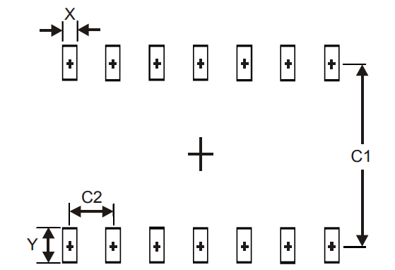
TSSOP-14
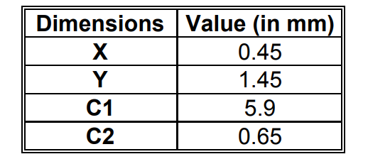
TSSOP-14
74HC08 Manufacturer
Diodes Incorporated is devoted to be the leading provider for large-volume and high-growing markets. With cutting-edge products of package technology, analog, discrete and mixed-signal products, Diodes Incorporated is capable to provide high-quality semiconductor products to meet the customers’ needs from walks of communications, computing, consumer electronics, automotive and industrial markets. Their product lines cover a wide range of application solutions together with 25 operations around the world which serve with examine, engineering, manufacturing and customer service.
Datasheet PDF
- Environmental Information :
- RohsStatement :
- Datasheets :
Trend Analysis
Are 74HC08 and 74LS08 acceptable?
74HC08 and 74LS08 are both quad-two inputs and gates, arranged on one foot. 74HC08 power supply voltage operating range is 2V-6V, 74LS08 power supply voltage is 5V. They are interchangeable when the supply voltage is 5V.
What’s the difference between 74LS08 and 74HC08?
74LS08 is TTL circuit, working power supply voltage is 5V. 74HC08 is a CMOS circuit, the chip power supply operating voltage range is 2V ~ 6V.
What exactly does the 74HC08D block do?
The 74HC08 provides four independent 2-input AND gates with standard push-pull outputs.
 74HC245 Transceiver IC: Price, Uses and Datasheet
30 August 20213264
 GRM21BR71C475KA73L Ceramic Capacitor: Datasheet, Price, GRM Series
15 March 2022388
 IRF3710 N-Channel Power MOSFET: Equivalent, Datasheet, Pinout
11 January 202217846
 Microchip PIC16F1613TIML Microcontroller Datasheet Overview
29 February 2024184
 SB330 Schottky Barrier Rectifier: Package, Pinout, and Datasheet
18 April 20221718
 TIP110 NPN Power Darlington Transistor: Pinout, Datasheet pdf and Equivalent
18 December 20213401
 P82B96 Bipolar IC: Pinout, 3D Model and Datasheet
02 November 20213002
 Unraveling the Texas Instruments MSP430F47x3/47x4 Microcontrollers: A Comprehensive Technical Analysis
29 February 2024225
 Introduction to buck, boost, and buck-boost converters
28 September 202125173
 RF Switches Guide: Types, Specifications & Applications
03 July 20255129
 What is a Cell Phone Antenna?
21 July 202133519
 Active Electroacoustic Resonator-Silent Speaker
10 November 20216192
 Tantalum Capacitors Explained: How They Work, Where They Fit, and How to Use Them Safely
14 July 202614002
 Utmel Christmas and New Year Carnival
07 December 20204236
 What is PWM "Dead Band"?
21 April 20228378
 Introduction to Optical Amplifier
27 March 202510399
Diodes Incorporated
In Stock: 2500
Minimum: 1 Multiples: 1
Qty
Unit Price
Ext Price
1
$1.091070
$1.09
10
$1.029311
$10.29
100
$0.971048
$97.10
500
$0.916083
$458.04
1000
$0.864230
$864.23
Not the price you want? Send RFQ Now and we'll contact you ASAP.
Inquire for More Quantity
![74LVC2G32HD4-7]() 74LVC2G32HD4-7
Diodes Incorporated
![74AUP2G06FW4-7]() 74AUP2G06FW4-7
Diodes Incorporated
![74LVC2G02HD4-7]() 74LVC2G02HD4-7
Diodes Incorporated
![74AHCT1G08W5-7]() 74AHCT1G08W5-7
Diodes Incorporated
![74AHC1G09W5-7]() 74AHC1G09W5-7
Diodes Incorporated
![74LVC2G04W6-7]() 74LVC2G04W6-7
Diodes Incorporated
![74LVC1G04SE-7]() 74LVC1G04SE-7
Diodes Incorporated
![74AHC1G08SE-7]() 74AHC1G08SE-7
Diodes Incorporated
![74LVC1G14SE-7]() 74LVC1G14SE-7
Diodes Incorporated
![74LVC1G04W5-7]() 74LVC1G04W5-7
Diodes Incorporated


