
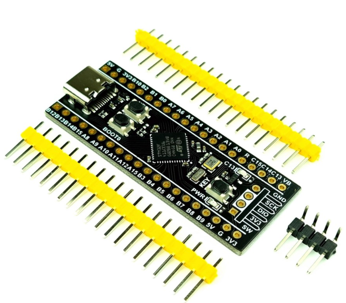
How to Download and Use the STM32F051K6T6 Datasheet

32KB 32K x 8 FLASH ARM® Cortex®-M0 32-Bit Microcontroller STM32F0 Series STM32F05 32 Pin 48MHz 3.3V 32-LQFP
Unit Price: $1.980000
Ext Price: $1.98


32KB 32K x 8 FLASH ARM® Cortex®-M0 32-Bit Microcontroller STM32F0 Series STM32F05 32 Pin 48MHz 3.3V 32-LQFP
Learn how to download the STM32F051K6T6 datasheet from trusted sources and use it effectively for embedded design, including pinout, specs, and guidelines.
Product Introduction
Finding the STM32F051K6T6 datasheet is simple when you know where to look. Start by visiting the official STMicroelectronics website. Use their search bar to locate the datasheet in PDF format. Alternatively, trusted distributors like Digi-Key or Mouser often provide datasheets alongside product listings. Always ensure the version is up-to-date to avoid errors in your design. The datasheet serves as an essential guide for working with this low-power mcu. It includes critical details for embedded applications, making it much more than just an instruction manual for electronic components.
Where to Download the STM32F051K6T6 Datasheet
Accessing the Official STMicroelectronics Website
The most reliable source for the STM32F051K6T6 datasheet is the official STMicroelectronics website. Start by visiting their homepage and using the search bar to locate the datasheet. Type "STM32F051K6T6" into the search field, and you will find a list of resources, including the datasheet in PDF format. The website ensures that you access the latest version of the document, which is crucial for accurate technical details.
Downloading directly from STMicroelectronics guarantees that the datasheet is authentic and free from errors. You can also explore additional resources, such as application notes and reference manuals, to complement the datasheet. These materials provide deeper insights into the mcu's capabilities and help you design more efficient systems.
Using Authorized Distributors for the Datasheet
If you prefer an alternative source, authorized distributors like Digi-Key, Mouser, or Arrow Electronics also provide the STM32F051K6T6 datasheet. These distributors include the datasheet alongside product listings, making it easy to download while purchasing components.
When using these platforms, ensure that the distributor is officially recognized by STMicroelectronics. This step minimizes the risk of downloading outdated or incorrect documents. Authorized distributors often provide additional technical support, which can be helpful during the design process.
Verifying the Datasheet's Version and Authenticity
Before using the STM32F051K6T6 datasheet, verify its version and authenticity. An outdated or tampered datasheet can lead to design errors and system failures. To confirm the document's reliability, check the version number and publication date on the first page. Compare these details with the latest version available on the STMicroelectronics website.
You can also use benchmarks to assess the datasheet's authenticity. The table below highlights two key benchmarks:
| Benchmark | Description |
|---|---|
| Document False Reject Rate (DFRR) | Measures the rate at which valid documents are incorrectly rejected. |
| Document False Accept Rate (DFAR) | Measures the rate at which invalid documents are incorrectly accepted. |
These benchmarks help ensure that the datasheet you are using is both valid and accurate. Always cross-reference the document with official sources to avoid potential issues in your design.
Key Sections of the STM32F051K6T6 Datasheet
Features and Specifications Overview
The STM32F051K6T6 datasheet begins with a detailed overview of the mcu's features and technical specifications. This section helps you understand the capabilities of the device and its suitability for your project. You’ll find information about the processor core, memory size, and supported peripherals. For example, the STM32F051K6T6 features an ARM Cortex-M0 core, which is optimized for low-power applications.
The datasheet also lists key specifications like clock speed, operating voltage range, and power consumption. These details allow you to evaluate the mcu's performance and compatibility with your design requirements. Pay close attention to the electrical characteristics, as they provide insights into how the device operates under different conditions.
To make the most of this section, compare the features with your project needs. If your design requires specific peripherals or memory configurations, this overview will help you decide whether the STM32F051K6T6 is the right choice.
Pin Configuration and Functions
The pinout section of the STM32F051K6T6 datasheet is crucial for understanding how to connect the mcu to other components. Each pin serves a specific function, such as power supply, input/output, or communication. The datasheet provides a pin configuration table that lists all pins, their names, and their alternate functions.
For example, some pins can be configured for GPIO, while others support communication protocols like SPI or I2C. You’ll also find details about pin numbering and layout, which are essential for designing your PCB.
When working with the pin configuration and functions, focus on the alternate functions of each pin. These allow you to use the same pin for multiple purposes, depending on your design needs. The datasheet explains how to configure these functions using software tools like STM32CubeMX.
Tip: Bookmark the pinout section for quick reference during the design phase. This will save you time when you need to verify pin functions or troubleshoot connections.
Block Diagram and Architecture Details
The block diagram in the STM32F051K6T6 datasheet provides a visual representation of the mcu's internal architecture. This diagram helps you understand how different components, such as the processor core, memory, and peripherals, interact with each other.
You’ll see how the ARM Cortex-M0 core connects to the Flash memory, SRAM, and communication interfaces. The datasheet also highlights the role of the clock system and power management unit in ensuring efficient operation.
Studying the block diagram allows you to identify potential bottlenecks or limitations in your design. For instance, if your application requires high-speed data transfer, you can check whether the mcu’s communication interfaces meet your requirements.
Note: Use the block diagram as a reference when planning your system architecture. It provides a clear picture of how the mcu operates, making it easier to optimize your design.
Electrical Characteristics and Operating Conditions
The STM32F051K6T6 datasheet includes a comprehensive section on electrical characteristics. This part is essential for understanding how the mcu performs under different conditions. You’ll find details about absolute maximum ratings, recommended operating conditions, and typical characteristics.
Absolute Maximum Ratings
Absolute maximum ratings define the limits the mcu can tolerate without permanent damage. These ratings include parameters like supply voltage, input/output pin voltage, and storage temperature. For example, the datasheet specifies the maximum voltage the mcu can handle across its power pins. Exceeding these ratings can lead to irreversible damage, so you must design your circuit to stay within these limits.
Tip: Always use components that match or exceed the mcu's ratings to ensure reliability.
Recommended Operating Conditions
Recommended operating conditions describe the ideal range for the mcu to function reliably. This includes parameters like operating voltage, ambient temperature, and clock frequency. For instance, the STM32F051K6T6 operates efficiently within a specific voltage range, ensuring stable performance across its interfaces.
You should design your system to stay within these conditions. This approach minimizes the risk of errors and ensures the mcu performs as expected.
Typical Characteristics
Typical characteristics provide average values for parameters like power consumption, signal rise times, and input/output voltage levels. These values help you estimate the mcu's behavior in real-world applications. For example, the datasheet might include graphs showing how power consumption varies with clock speed.
Use these typical characteristics to optimize your design. If your application requires low power consumption, you can adjust the clock frequency or operating voltage accordingly.
Note: Refer to the electrical characteristics section frequently during the design phase. It provides critical information for ensuring your circuit operates within safe and efficient limits.
Memory Map and Peripheral Information
The STM32F051K6T6 datasheet includes a detailed memory map that outlines the organization of the mcu's memory. This section is crucial for understanding how the processor accesses Flash memory, SRAM, and peripheral registers.
Memory Map
The memory map shows the address ranges for different memory types. For example, Flash memory is typically used for storing program code, while SRAM is reserved for runtime data. The datasheet specifies the size and location of each memory block, helping you allocate resources effectively.
You can use this information to plan your software architecture. If your application requires extensive data storage, you’ll know how much SRAM is available and whether additional external memory is needed.
Peripheral Information
Peripheral information describes the mcu's built-in interfaces, such as GPIO, SPI, I2C, and UART. Each peripheral has specific registers for configuration and operation. The datasheet provides details about these registers, including their addresses and functions.
For example, the STM32F051K6T6 supports multiple communication interfaces, allowing you to connect sensors, actuators, or other devices. The datasheet explains how to configure these interfaces using software tools like STM32CubeMX.
Callout: Use the memory map and peripheral information to streamline your software development process. These sections provide a clear roadmap for accessing and configuring the mcu's resources.
How to Read a Datasheet for Design and Implementation
Interpreting Pin Descriptions and Alternate Functions
When working with microcontrollers like the STM32F051K6T6, understanding pin descriptions is essential for embedded applications. Each pin has a specific role, such as power supply, input/output, or communication. The datasheet provides a detailed table that lists pin names, numbers, and alternate functions.
Alternate functions allow you to use a single pin for multiple purposes. For example, a pin might serve as a GPIO in one configuration and as an SPI interface in another. You can configure these functions using software tools like STM32CubeMX. This flexibility helps you optimize your design by reducing the number of components needed.
To interpret pin descriptions effectively, focus on the pinout table in the datasheet. Match the pin functions with your application's requirements. If your design involves communication protocols like I2C or UART, ensure the pins support these features.
Tip: Keep the pinout section bookmarked for quick reference during circuit design. It saves time and prevents errors when connecting components.
Using Electrical Characteristics for Circuit Design
Electrical characteristics play a critical role in ensuring your circuit operates reliably. The STM32F051K6T6 datasheet includes parameters like operating voltage, power consumption, and signal rise times. These details help you design circuits that meet your application's needs.
Start by reviewing the recommended operating conditions. For example, the mcu performs best within a specific voltage range. Staying within this range ensures stable operation and prevents damage. Next, examine the absolute maximum ratings. These values define the limits the mcu can tolerate without permanent damage.
Typical characteristics, such as power consumption graphs, provide insights into real-world performance. If your application requires low power consumption, adjust the clock frequency or voltage accordingly.
Note: Use electrical characteristics to select compatible components and optimize your design for efficiency.
Understanding Timing Diagrams for Performance Optimization
Timing diagrams illustrate how signals interact within the mcu. These diagrams are crucial for optimizing performance in embedded applications. The STM32F051K6T6 datasheet includes timing diagrams for communication protocols, memory access, and signal transitions.
To analyze timing diagrams effectively, compare different methods for performance optimization. The table below highlights three statistical techniques used for timing analysis:
| Method | Description |
|---|---|
| Statistical Static Timing Analysis (SSTA) | Treats delays as random variables, allowing for delay distribution determination across paths. |
| Binary Integer Programming | Utilized for optimization purposes in performance analysis. |
| Geometric Programming | Another technique employed for optimization in timing diagram comparisons. |
These methods help you identify bottlenecks and improve signal timing. For example, if your application involves high-speed data transfer, use timing diagrams to ensure signals transition smoothly.
Callout: Timing diagrams are a powerful tool for optimizing embedded systems. Use them to fine-tune your design and achieve peak performance.
Applying Layout Guidelines for PCB Design
Designing a printed circuit board (PCB) for the STM32F051K6T6 requires careful planning to ensure optimal performance. Following layout guidelines helps you avoid issues like signal interference, power instability, or overheating. Here are some essential tips to keep in mind:
Place Components Strategically
Position the mcu and other critical components near the center of the PCB. This reduces trace lengths and minimizes signal delays. Group related components, such as decoupling capacitors, close to the mcu to improve power stability.Optimize Ground and Power Planes
Use a solid ground plane to reduce noise and improve signal integrity. Ensure the power plane is wide enough to handle current flow without overheating. Avoid splitting the ground plane unnecessarily, as this can create unwanted loops.Route Traces Efficiently
Keep traces as short and direct as possible. Avoid sharp angles; instead, use 45-degree bends to reduce signal reflections. For high-speed signals, maintain consistent trace widths and spacing to prevent crosstalk.Follow Decoupling Capacitor Guidelines
Place decoupling capacitors close to the mcu's power pins. These capacitors filter out noise and stabilize the power supply. Use the values recommended in the datasheet for best results.Separate Analog and Digital Signals
Keep analog and digital signal traces apart to prevent interference. If the mcu has both analog and digital functions, route their signals on separate layers or areas of the PCB.
Tip: Use PCB design software like KiCad or Altium Designer to simulate your layout. These tools help you identify potential issues before manufacturing.
By following these guidelines, you can create a reliable PCB that maximizes the performance of your mcu and ensures long-term stability.
Tips for Using the STM32F051K6T6 Datasheet Effectively
Bookmarking Key Sections for Quick Reference
Bookmarking key sections in the STM32F051K6T6 datasheet saves time during design and troubleshooting. Focus on areas like pin configuration, electrical characteristics, and memory maps. These sections contain essential details that you’ll frequently reference.
For example, when configuring pins for communication protocols, you can quickly locate the pinout table instead of scrolling through the entire document. Use digital tools like PDF readers to create bookmarks or annotations. This method ensures you access critical information instantly without disrupting your workflow.
Tip: Highlight sections with color-coded bookmarks based on their relevance to your project. This visual organization makes navigation even faster.
Cross-Referencing with Application Notes and Resources
Cross-referencing the STM32F051K6T6 datasheet with application notes and related resources enhances your understanding of the mcu. Application notes provide practical examples and additional insights that complement the datasheet.
Here’s how cross-referencing benefits your design process:
| Feature | Benefit |
|---|---|
| Instant Jump to Referenced Content | Eliminates manual scrolling, enhancing efficiency in large documents. |
| Hyperlinking Footnotes and Endnotes | Improves readability by allowing direct access to supplementary information without disrupting flow. |
| Precision Hyperlinks | Directs readers to specific locations on a page, reducing cognitive load and improving information retrieval. |
| Interactive Tables of Contents | Transforms traditional navigation tools into interactive systems, allowing quick access to content. |
When designing circuits, use application notes to verify datasheet details. For instance, if the datasheet specifies a pin’s alternate function, an application note might explain how to configure it in software. This approach ensures accuracy and reduces errors.
Callout: Combine datasheets and application notes to create a comprehensive reference library for your project.
Staying Updated with the Latest Datasheet Versions
Using outdated datasheets can lead to design errors. Always check for the latest version of the STM32F051K6T6 datasheet on the STMicroelectronics website. Updated versions often include corrections, new features, or improved explanations.
To stay informed, subscribe to notifications from STMicroelectronics or authorized distributors. These alerts notify you when new versions become available. Additionally, compare the version number and publication date of your datasheet with the latest one online.
Note: Regularly updating your datasheet ensures your design aligns with the most accurate and reliable information.
Leveraging Community Forums for Additional Insights
Community forums offer a wealth of knowledge for working with the STM32F051K6T6 and similar microcontrollers. These platforms connect you with engineers, hobbyists, and developers who share their experiences and solutions. By participating in these forums, you can gain practical insights that complement the datasheet.
Start by exploring popular forums like the ST Community, Stack Overflow, and Reddit’s embedded systems subreddits. These platforms often feature discussions about common challenges, troubleshooting tips, and design recommendations. You can search for threads related to the STM32F051K6T6 or post your own questions to get targeted advice.
When using forums, focus on threads that include verified answers or contributions from experienced users. Many forums allow users to upvote helpful responses, making it easier to identify reliable information. For example, if you encounter issues configuring the mcu’s GPIO pins, you might find step-by-step solutions shared by other developers.
Tip: Bookmark threads that provide detailed explanations or code snippets. These resources can save you time during future projects.
Forums also serve as a great place to discover unofficial tools and libraries that enhance the functionality of your mcu. Developers often share open-source projects or custom configurations that simplify complex tasks. While these resources are not officially supported, they can be valuable for prototyping and experimentation.
Finally, contribute to the community by sharing your own experiences. Posting solutions to problems you’ve solved helps others and builds your reputation as a knowledgeable contributor. Active participation ensures you stay updated on the latest trends and techniques in embedded systems design.
Downloading the STM32F051K6T6 datasheet from trusted sources ensures you access accurate and reliable information. Each section of the datasheet, from pin configurations to electrical characteristics, plays a vital role in helping you design and implement your project effectively. By thoroughly exploring the datasheet, you can unlock the full potential of this mcu and create optimized, efficient systems. Take the time to study it carefully and use it as a guide for your specific applications.
FAQ
What is the STM32F051K6T6 used for?
This microcontroller (mcu) is ideal for low-power embedded applications. It supports tasks like motor control, sensor interfacing, and communication protocols. Its compact size and efficient architecture make it suitable for consumer electronics, industrial automation, and IoT devices.
How do I configure the pins for alternate functions?
Use the STM32CubeMX software to configure pins. Select the desired alternate function for each pin, such as GPIO, SPI, or I2C. The datasheet provides a pinout table to guide you in choosing the correct configuration for your application.
Where can I find additional resources for the STM32F051K6T6?
Visit the STMicroelectronics website for application notes, reference manuals, and software tools. Community forums like the ST Community and Stack Overflow also offer valuable insights and troubleshooting tips from experienced developers.
How do I ensure my design stays within electrical limits?
Refer to the electrical characteristics section of the datasheet. Design your circuit to operate within the recommended voltage and temperature ranges. Use decoupling capacitors near power pins to stabilize the supply and prevent damage.
Can I use the STM32F051K6T6 for battery-powered devices?
Yes, this mcu is optimized for low-power applications. Its efficient architecture and power-saving modes make it suitable for battery-powered devices like wearables, remote sensors, and portable gadgets.
Specifications
- TypeParameter
- Lifecycle Status
Lifecycle Status refers to the current stage of an electronic component in its product life cycle, indicating whether it is active, obsolete, or transitioning between these states. An active status means the component is in production and available for purchase. An obsolete status indicates that the component is no longer being manufactured or supported, and manufacturers typically provide a limited time frame for support. Understanding the lifecycle status is crucial for design engineers to ensure continuity and reliability in their projects.
ACTIVE (Last Updated: 7 months ago) - Factory Lead Time10 Weeks
- Mounting Type
The "Mounting Type" in electronic components refers to the method used to attach or connect a component to a circuit board or other substrate, such as through-hole, surface-mount, or panel mount.
Surface Mount - Package / Case
refers to the protective housing that encases an electronic component, providing mechanical support, electrical connections, and thermal management.
32-LQFP - Surface Mount
having leads that are designed to be soldered on the side of a circuit board that the body of the component is mounted on.
YES - Number of Pins32
- Data ConvertersA/D 13x12b; D/A 1x12b
- Number of I/Os25
- Watchdog TimersYes
- Operating Temperature
The operating temperature is the range of ambient temperature within which a power supply, or any other electrical equipment, operate in. This ranges from a minimum operating temperature, to a peak or maximum operating temperature, outside which, the power supply may fail.
-40°C~85°C TA - Packaging
Semiconductor package is a carrier / shell used to contain and cover one or more semiconductor components or integrated circuits. The material of the shell can be metal, plastic, glass or ceramic.
Tray - Series
In electronic components, the "Series" refers to a group of products that share similar characteristics, designs, or functionalities, often produced by the same manufacturer. These components within a series typically have common specifications but may vary in terms of voltage, power, or packaging to meet different application needs. The series name helps identify and differentiate between various product lines within a manufacturer's catalog.
STM32F0 - JESD-609 Code
The "JESD-609 Code" in electronic components refers to a standardized marking code that indicates the lead-free solder composition and finish of electronic components for compliance with environmental regulations.
e3 - Part Status
Parts can have many statuses as they progress through the configuration, analysis, review, and approval stages.
Active - Moisture Sensitivity Level (MSL)
Moisture Sensitivity Level (MSL) is a standardized rating that indicates the susceptibility of electronic components, particularly semiconductors, to moisture-induced damage during storage and the soldering process, defining the allowable exposure time to ambient conditions before they require special handling or baking to prevent failures
3 (168 Hours) - Number of Terminations32
- Terminal Finish
Terminal Finish refers to the surface treatment applied to the terminals or leads of electronic components to enhance their performance and longevity. It can improve solderability, corrosion resistance, and overall reliability of the connection in electronic assemblies. Common finishes include nickel, gold, and tin, each possessing distinct properties suitable for various applications. The choice of terminal finish can significantly impact the durability and effectiveness of electronic devices.
Tin (Sn) - Max Power Dissipation
The maximum power that the MOSFET can dissipate continuously under the specified thermal conditions.
357mW - Terminal Position
In electronic components, the term "Terminal Position" refers to the physical location of the connection points on the component where external electrical connections can be made. These connection points, known as terminals, are typically used to attach wires, leads, or other components to the main body of the electronic component. The terminal position is important for ensuring proper connectivity and functionality of the component within a circuit. It is often specified in technical datasheets or component specifications to help designers and engineers understand how to properly integrate the component into their circuit designs.
QUAD - Terminal Form
Occurring at or forming the end of a series, succession, or the like; closing; concluding.
GULL WING - Supply Voltage
Supply voltage refers to the electrical potential difference provided to an electronic component or circuit. It is crucial for the proper operation of devices, as it powers their functions and determines performance characteristics. The supply voltage must be within specified limits to ensure reliability and prevent damage to components. Different electronic devices have specific supply voltage requirements, which can vary widely depending on their design and intended application.
3.3V - Frequency
In electronic components, the parameter "Frequency" refers to the rate at which a signal oscillates or cycles within a given period of time. It is typically measured in Hertz (Hz) and represents how many times a signal completes a full cycle in one second. Frequency is a crucial aspect in electronic components as it determines the behavior and performance of various devices such as oscillators, filters, and communication systems. Understanding the frequency characteristics of components is essential for designing and analyzing electronic circuits to ensure proper functionality and compatibility with other components in a system.
48MHz - Base Part Number
The "Base Part Number" (BPN) in electronic components serves a similar purpose to the "Base Product Number." It refers to the primary identifier for a component that captures the essential characteristics shared by a group of similar components. The BPN provides a fundamental way to reference a family or series of components without specifying all the variations and specific details.
STM32F05 - Power Supplies
an electronic circuit that converts the voltage of an alternating current (AC) into a direct current (DC) voltage.?
2.5/3.3V - Supply Voltage-Min (Vsup)
The parameter "Supply Voltage-Min (Vsup)" in electronic components refers to the minimum voltage level required for the component to operate within its specified performance range. This parameter indicates the lowest voltage that can be safely applied to the component without risking damage or malfunction. It is crucial to ensure that the supply voltage provided to the component meets or exceeds this minimum value to ensure proper functionality and reliability. Failure to adhere to the specified minimum supply voltage may result in erratic behavior, reduced performance, or even permanent damage to the component.
2V - Interface
In electronic components, the term "Interface" refers to the point at which two different systems, devices, or components connect and interact with each other. It can involve physical connections such as ports, connectors, or cables, as well as communication protocols and standards that facilitate the exchange of data or signals between the connected entities. The interface serves as a bridge that enables seamless communication and interoperability between different parts of a system or between different systems altogether. Designing a reliable and efficient interface is crucial in ensuring proper functionality and performance of electronic components and systems.
HDMI, I2C, I2S, IrDA, LIN, SPI, UART, USART - Memory Size
The memory capacity is the amount of data a device can store at any given time in its memory.
32kB - Oscillator Type
Wien Bridge Oscillator; RC Phase Shift Oscillator; Hartley Oscillator; Voltage Controlled Oscillator; Colpitts Oscillator; Clapp Oscillators; Crystal Oscillators; Armstrong Oscillator.
Internal - RAM Size
RAM size refers to the amount of random access memory (RAM) available in an electronic component, such as a computer or smartphone. RAM is a type of volatile memory that stores data and instructions that are actively being used by the device's processor. The RAM size is typically measured in gigabytes (GB) and determines how much data the device can store and access quickly for processing. A larger RAM size allows for smoother multitasking, faster loading times, and better overall performance of the electronic component. It is an important factor to consider when choosing a device, especially for tasks that require a lot of memory, such as gaming, video editing, or running multiple applications simultaneously.
8K x 8 - Voltage - Supply (Vcc/Vdd)
Voltage - Supply (Vcc/Vdd) is a key parameter in electronic components that specifies the voltage level required for the proper operation of the device. It represents the power supply voltage that needs to be provided to the component for it to function correctly. This parameter is crucial as supplying the component with the correct voltage ensures that it operates within its specified limits and performance characteristics. It is typically expressed in volts (V) and is an essential consideration when designing and using electronic circuits to prevent damage and ensure reliable operation.
2V~3.6V - uPs/uCs/Peripheral ICs Type
The parameter "uPs/uCs/Peripheral ICs Type" refers to the classification of various integrated circuits used in electronic devices. It encompasses microprocessors (uPs), microcontrollers (uCs), and peripheral integrated circuits that provide additional functionalities. This classification helps in identifying the specific type of chip used for processing tasks, controlling hardware, or interfacing with other components in a system. Understanding this parameter is essential for selecting the appropriate electronic components for a given application.
MICROCONTROLLER, RISC - Core Processor
The term "Core Processor" typically refers to the central processing unit (CPU) of a computer or electronic device. It is the primary component responsible for executing instructions, performing calculations, and managing data within the system. The core processor is often considered the brain of the device, as it controls the overall operation and functionality. It is crucial for determining the speed and performance capabilities of the device, as well as its ability to handle various tasks and applications efficiently. In modern devices, core processors can have multiple cores, allowing for parallel processing and improved multitasking capabilities.
ARM® Cortex®-M0 - Peripherals
In the context of electronic components, "Peripherals" refer to devices or components that are connected to a main system or device to enhance its functionality or provide additional features. These peripherals can include input devices such as keyboards, mice, and touchscreens, as well as output devices like monitors, printers, and speakers. Other examples of peripherals include external storage devices, network adapters, and cameras. Essentially, peripherals are external devices that expand the capabilities of a main electronic system or device.
DMA, I2S, POR, PWM, WDT - Program Memory Type
Program memory typically refers to flash memory when it is used to hold the program (instructions). Program memory may also refer to a hard drive or solid state drive (SSD). Contrast with data memory.
FLASH - Core Size
Core size in electronic components refers to the physical dimensions of the core material used in devices such as inductors and transformers. The core size directly impacts the performance characteristics of the component, including its inductance, saturation current, and frequency response. A larger core size typically allows for higher power handling capabilities and lower core losses, while a smaller core size may result in a more compact design but with limitations on power handling and efficiency. Designers must carefully select the core size based on the specific requirements of the application to achieve optimal performance and efficiency.
32-Bit - Program Memory Size
Program Memory Size refers to the amount of memory available in an electronic component, such as a microcontroller or microprocessor, that is used to store program instructions. This memory is non-volatile, meaning that the data stored in it is retained even when the power is turned off. The program memory size determines the maximum amount of code that can be stored and executed by the electronic component. It is an important parameter to consider when selecting a component for a specific application, as insufficient program memory size may limit the functionality or performance of the device.
32KB 32K x 8 - Connectivity
In electronic components, "Connectivity" refers to the ability of a component to establish and maintain connections with other components or devices within a circuit. It is a crucial parameter that determines how easily signals can be transmitted between different parts of a circuit. Connectivity can be influenced by factors such as the number of input and output ports, the type of connectors used, and the overall design of the component. Components with good connectivity are essential for ensuring reliable and efficient operation of electronic systems.
HDMI-CEC, I2C, IrDA, LINbus, SPI, UART/USART - Supply Current-Max
Supply Current-Max refers to the maximum amount of current that an electronic component or circuit can draw from its power supply under specified operating conditions. It is a critical parameter that determines the power consumption and thermal performance of the device. Exceeding this limit can lead to overheating, potential damage, or failure of the component. Knowing the Supply Current-Max helps in designing circuits that ensure proper operation and reliability.
23.2mA - Bit Size
In electronic components, "Bit Size" refers to the number of bits that can be processed or stored by a particular component. A bit is the smallest unit of data in computing and can have a value of either 0 or 1. The Bit Size parameter is commonly used to describe the capacity or performance of components such as microprocessors, memory modules, and data buses. A larger Bit Size generally indicates a higher processing capability or storage capacity, allowing for more complex operations and larger amounts of data to be handled efficiently. It is an important specification to consider when selecting electronic components for specific applications that require certain levels of performance and data processing capabilities.
32 - Has ADC
Has ADC refers to the presence of an Analog-to-Digital Converter (ADC) in an electronic component. An ADC is a crucial component in many electronic devices as it converts analog signals, such as voltage or current, into digital data that can be processed by a digital system. Having an ADC allows the electronic component to interface with analog signals and convert them into a format that can be manipulated and analyzed digitally. This parameter is important for applications where analog signals need to be converted into digital form for further processing or control.
YES - DMA Channels
DMA (Direct Memory Access) Channels are a feature found in electronic components such as microcontrollers, microprocessors, and peripheral devices. DMA Channels allow data to be transferred directly between peripherals and memory without involving the CPU, thereby reducing the burden on the CPU and improving overall system performance. Each DMA Channel is typically assigned to a specific peripheral device or memory region, enabling efficient data transfer operations. The number of DMA Channels available in a system determines the concurrent data transfer capabilities and can vary depending on the specific hardware design. Overall, DMA Channels play a crucial role in optimizing data transfer efficiency and system performance in electronic devices.
YES - Data Bus Width
The data bus width in electronic components refers to the number of bits that can be transferred simultaneously between the processor and memory. It determines the amount of data that can be processed and transferred in a single operation. A wider data bus allows for faster data transfer speeds and improved overall performance of the electronic device. Common data bus widths include 8-bit, 16-bit, 32-bit, and 64-bit, with higher numbers indicating a larger capacity for data transfer. The data bus width is an important specification to consider when evaluating the speed and efficiency of a computer system or other electronic device.
32b - Number of Timers/Counters8
- Core Architecture
In electronic components, the term "Core Architecture" refers to the fundamental design and structure of the component's internal circuitry. It encompasses the arrangement of key components, such as processors, memory units, and input/output interfaces, within the device. The core architecture plays a crucial role in determining the component's performance, power efficiency, and overall capabilities. Different core architectures are optimized for specific applications and requirements, such as high-speed processing, low power consumption, or specialized functions. Understanding the core architecture of electronic components is essential for engineers and designers to select the most suitable components for their projects.
ARM - CPU Family
CPU Family refers to a classification of microprocessors that share a common architecture and design traits. It signifies a group of processors that are typically produced by the same manufacturer and have similar functionality and features. The CPU Family can encompass various models that may differ in performance, power consumption, and specific capabilities but retain a unified core design, allowing for compatibility with software and hardware. This classification helps users and developers to understand the performance characteristics and upgrade pathways of different CPU models within the same family.
CORTEX-M0 - Number of ADC Channels13
- Number of PWM Channels6
- Number of I2C Channels1
- Height1.45mm
- Length7mm
- Width7.2mm
- REACH SVHC
The parameter "REACH SVHC" in electronic components refers to the compliance with the Registration, Evaluation, Authorization, and Restriction of Chemicals (REACH) regulation regarding Substances of Very High Concern (SVHC). SVHCs are substances that may have serious effects on human health or the environment, and their use is regulated under REACH to ensure their safe handling and minimize their impact.Manufacturers of electronic components need to declare if their products contain any SVHCs above a certain threshold concentration and provide information on the safe use of these substances. This information allows customers to make informed decisions about the potential risks associated with using the components and take appropriate measures to mitigate any hazards.Ensuring compliance with REACH SVHC requirements is essential for electronics manufacturers to meet regulatory standards, protect human health and the environment, and maintain transparency in their supply chain. It also demonstrates a commitment to sustainability and responsible manufacturing practices in the electronics industry.
No SVHC - Radiation Hardening
Radiation hardening is the process of making electronic components and circuits resistant to damage or malfunction caused by high levels of ionizing radiation, especially for environments in outer space (especially beyond the low Earth orbit), around nuclear reactors and particle accelerators, or during nuclear accidents or nuclear warfare.
No - RoHS Status
RoHS means “Restriction of Certain Hazardous Substances” in the “Hazardous Substances Directive” in electrical and electronic equipment.
ROHS3 Compliant - Lead Free
Lead Free is a term used to describe electronic components that do not contain lead as part of their composition. Lead is a toxic material that can have harmful effects on human health and the environment, so the electronics industry has been moving towards lead-free components to reduce these risks. Lead-free components are typically made using alternative materials such as silver, copper, and tin. Manufacturers must comply with regulations such as the Restriction of Hazardous Substances (RoHS) directive to ensure that their products are lead-free and environmentally friendly.
Lead Free
Parts with Similar Specs
- ImagePart NumberManufacturerPackage / CaseNumber of PinsCore ArchitectureData Bus WidthNumber of I/OInterfaceMemory SizeSupply VoltageView Compare
![STM32F051K6T6]()
STM32F051K6T6
32-LQFP
32
ARM
32 b
25
HDMI, I2C, I2S, IrDA, LIN, SPI, UART, USART
32 kB
3.3 V
![STM32F042K6T6]()
32-LQFP
32
ARM
32 b
26
CAN, HDMI, I2C, I2S, IrDA, LIN, SPI, UART, USART, USB
32 kB
3.3 V
![MKL05Z32VLC4]()
32-LQFP
32
ARM
32 b
25
I2C, IrDA, LIN, SPI, UART, USART
32 kB
3.3 V
![STM32F031K6T6]()
32-LQFP
32
ARM
32 b
25
I2C, I2S, IrDA, LIN, SPI, UART, USART
32 kB
3.3 V
![STM32F031K6T7]()
32-LQFP
-
-
-
28
-
-
3.3 V


Datasheet PDF
- Datasheets :
 IRF830 Power MOSFET: Pinout, Datasheet, and Test Circuit
14 July 20214863
 LTC6905IS5-133#TRPBF: Programmable Timer and Oscillator for Precision Timing Applications
06 March 2024181
 CSR8675 Premium Single-Chip : Datasheet, Features and Specifications
28 July 20218747
 STM32F411CEU6: Overview, Features, Specification
14 October 20234933
 MPC8540 PowerQUICC III Integrated Host Processor: A Comprehensive Overview
16 September 2025414
 LTC7545ABSW#TRPBF Digital to Analog Converter: Product Overview and Applications
06 March 2024129
![AD584 Precision Voltage Reference: Pinout, Features and Datasheet [FAQ]](https://res.utmel.com/Images/Article/0f6e8ef3-90eb-47b0-bdf7-30e675aaf8f5.png) AD584 Precision Voltage Reference: Pinout, Features and Datasheet [FAQ]
AD584 Precision Voltage Reference: Pinout, Features and Datasheet [FAQ]06 May 20222277
 TXS0104ERGYR: 4-Bit Bidirectional Voltage-Level Translator, Datasheet
22 March 20221494
 PMIC - Gate Drivers: A Purpose-Built Integrated Circuit
22 February 20231588
 Optimizations and applications of wide-band gap (wbg) semiconductor devices for ev systems
28 October 20222056
 ICinsights:MCUs Will Continue to Rise in Price
30 March 20224016
 What is Metaverse?
09 October 20212708
 How Does the A4988 Stepper Motor Driver Work
27 February 20233831
 Building a Smart Home System: Exploring Arduino Applications
13 March 20242456
 Vibration Isolator: Types and Applications
13 January 202110506
 What is a Power Capacitor?
20 November 20215723
STMicroelectronics
In Stock: 3000
Minimum: 1 Multiples: 1
Qty
Unit Price
Ext Price
1
$1.980000
$1.98
10
$1.867925
$18.68
100
$1.762193
$176.22
500
$1.662446
$831.22
1000
$1.568345
$1,568.34
Not the price you want? Send RFQ Now and we'll contact you ASAP.
Inquire for More Quantity
![STM32F103RBT6]() STM32F103RBT6
STM32F103RBT6STMicroelectronics
![STM32F103ZET6]() STM32F103ZET6
STM32F103ZET6STMicroelectronics
![STM32H743IIT6]() STM32H743IIT6
STM32H743IIT6STMicroelectronics
![STM32F407VET6]() STM32F407VET6
STM32F407VET6STMicroelectronics
![STM32F405RGT6]() STM32F405RGT6
STM32F405RGT6STMicroelectronics
![STM32F030C8T6]() STM32F030C8T6
STM32F030C8T6STMicroelectronics
![STM32F100C8T6B]() STM32F100C8T6B
STM32F100C8T6BSTMicroelectronics
![STM32F103VBT6]() STM32F103VBT6
STM32F103VBT6STMicroelectronics
![STM8S003F3U6TR]() STM8S003F3U6TR
STM8S003F3U6TRSTMicroelectronics
![STM32F429ZIT6]() STM32F429ZIT6
STM32F429ZIT6STMicroelectronics


