
 Product
 Brand
Brand Articles
 Tools
Tools
BQ2005S Fast- Charge IC: Datasheet, Alternatives, Block Diagram


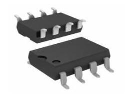
Constant Pulsed BQ2005 20-SOIC (0.295, 7.50mm Width) Tube 2A 20 Terminals 20 Pin
BQ2005S is a fast-charge IC for dual battery packs. This article covers more detailed information about BQ2005S.
BQ2005S Pinout

BQ2005S Pinout
BQ2005S CAD Model
Symbol

B2005S Symbol
Footprint

BQ2005S Footprint
3D Model

BQ2005S 3D Model
BQ2005S Description
The BQ2005S Fast-Charge IC provides comprehensive fast charge control functions together with high-speed switching power control circuitry on a monolithic CMOS device for sequential charge management in dual battery pack applications.
Specifications
- TypeParameter
- Lifecycle Status
Lifecycle Status refers to the current stage of an electronic component in its product life cycle, indicating whether it is active, obsolete, or transitioning between these states. An active status means the component is in production and available for purchase. An obsolete status indicates that the component is no longer being manufactured or supported, and manufacturers typically provide a limited time frame for support. Understanding the lifecycle status is crucial for design engineers to ensure continuity and reliability in their projects.
ACTIVE (Last Updated: 3 days ago) - Factory Lead Time6 Weeks
- Contact Plating
Contact plating (finish) provides corrosion protection for base metals and optimizes the mechanical and electrical properties of the contact interfaces.
Gold - Mounting Type
The "Mounting Type" in electronic components refers to the method used to attach or connect a component to a circuit board or other substrate, such as through-hole, surface-mount, or panel mount.
Surface Mount - Package / Case
refers to the protective housing that encases an electronic component, providing mechanical support, electrical connections, and thermal management.
20-SOIC (0.295, 7.50mm Width) - Surface Mount
having leads that are designed to be soldered on the side of a circuit board that the body of the component is mounted on.
YES - Number of Pins20
- Weight537.308512mg
- SwitchingFrequency300kHz
- Operating Temperature
The operating temperature is the range of ambient temperature within which a power supply, or any other electrical equipment, operate in. This ranges from a minimum operating temperature, to a peak or maximum operating temperature, outside which, the power supply may fail.
-20°C~70°C TA - Packaging
Semiconductor package is a carrier / shell used to contain and cover one or more semiconductor components or integrated circuits. The material of the shell can be metal, plastic, glass or ceramic.
Tube - JESD-609 Code
The "JESD-609 Code" in electronic components refers to a standardized marking code that indicates the lead-free solder composition and finish of electronic components for compliance with environmental regulations.
e4 - Pbfree Code
The "Pbfree Code" parameter in electronic components refers to the code or marking used to indicate that the component is lead-free. Lead (Pb) is a toxic substance that has been widely used in electronic components for many years, but due to environmental concerns, there has been a shift towards lead-free alternatives. The Pbfree Code helps manufacturers and users easily identify components that do not contain lead, ensuring compliance with regulations and promoting environmentally friendly practices. It is important to pay attention to the Pbfree Code when selecting electronic components to ensure they meet the necessary requirements for lead-free applications.
yes - Part Status
Parts can have many statuses as they progress through the configuration, analysis, review, and approval stages.
Active - Moisture Sensitivity Level (MSL)
Moisture Sensitivity Level (MSL) is a standardized rating that indicates the susceptibility of electronic components, particularly semiconductors, to moisture-induced damage during storage and the soldering process, defining the allowable exposure time to ambient conditions before they require special handling or baking to prevent failures
1 (Unlimited) - Number of Terminations20
- ECCN Code
An ECCN (Export Control Classification Number) is an alphanumeric code used by the U.S. Bureau of Industry and Security to identify and categorize electronic components and other dual-use items that may require an export license based on their technical characteristics and potential for military use.
EAR99 - Additional Feature
Any Feature, including a modified Existing Feature, that is not an Existing Feature.
DUAL BATTERY FAST CHARGER - HTS Code
HTS (Harmonized Tariff Schedule) codes are product classification codes between 8-1 digits. The first six digits are an HS code, and the countries of import assign the subsequent digits to provide additional classification. U.S. HTS codes are 1 digits and are administered by the U.S. International Trade Commission.
8542.39.00.01 - Terminal Position
In electronic components, the term "Terminal Position" refers to the physical location of the connection points on the component where external electrical connections can be made. These connection points, known as terminals, are typically used to attach wires, leads, or other components to the main body of the electronic component. The terminal position is important for ensuring proper connectivity and functionality of the component within a circuit. It is often specified in technical datasheets or component specifications to help designers and engineers understand how to properly integrate the component into their circuit designs.
DUAL - Terminal Form
Occurring at or forming the end of a series, succession, or the like; closing; concluding.
GULL WING - Peak Reflow Temperature (Cel)
Peak Reflow Temperature (Cel) is a parameter that specifies the maximum temperature at which an electronic component can be exposed during the reflow soldering process. Reflow soldering is a common method used to attach electronic components to a circuit board. The Peak Reflow Temperature is crucial because it ensures that the component is not damaged or degraded during the soldering process. Exceeding the specified Peak Reflow Temperature can lead to issues such as component failure, reduced performance, or even permanent damage to the component. It is important for manufacturers and assemblers to adhere to the recommended Peak Reflow Temperature to ensure the reliability and functionality of the electronic components.
260 - Number of Functions1
- Terminal Pitch
The center distance from one pole to the next.
1.27mm - Base Part Number
The "Base Part Number" (BPN) in electronic components serves a similar purpose to the "Base Product Number." It refers to the primary identifier for a component that captures the essential characteristics shared by a group of similar components. The BPN provides a fundamental way to reference a family or series of components without specifying all the variations and specific details.
BQ2005 - Pin Count
a count of all of the component leads (or pins)
20 - Operating Supply Voltage
The voltage level by which an electrical system is designated and to which certain operating characteristics of the system are related.
5V - Input Voltage-Nom
Input Voltage-Nom refers to the nominal or rated input voltage that an electronic component or device is designed to operate within. This parameter specifies the voltage level at which the component is expected to function optimally and safely. It is important to ensure that the actual input voltage supplied to the component does not exceed this nominal value to prevent damage or malfunction. Manufacturers provide this specification to guide users in selecting the appropriate power supply or input voltage source for the component. It is a critical parameter to consider when designing or using electronic circuits to ensure reliable performance and longevity of the component.
5V - Max Supply Voltage
In general, the absolute maximum common-mode voltage is VEE-0.3V and VCC+0.3V, but for products without a protection element at the VCC side, voltages up to the absolute maximum rated supply voltage (i.e. VEE+36V) can be supplied, regardless of supply voltage.
5.5V - Min Supply Voltage
The minimum supply voltage (V min ) is explored for sequential logic circuits by statistically simulating the impact of within-die process variations and gate-dielectric soft breakdown on data retention and hold time.
4.5V - Analog IC - Other Type
Analog IC - Other Type is a parameter used to categorize electronic components that are integrated circuits (ICs) designed for analog signal processing but do not fall into more specific subcategories such as amplifiers, comparators, or voltage regulators. These ICs may include specialized analog functions such as analog-to-digital converters (ADCs), digital-to-analog converters (DACs), voltage references, or signal conditioning circuits. They are typically used in various applications where precise analog signal processing is required, such as in audio equipment, instrumentation, communication systems, and industrial control systems. Manufacturers provide detailed specifications for these components to help engineers select the most suitable IC for their specific design requirements.
BATTERY CHARGE CONTROLLER - Output Current
The rated output current is the maximum load current that a power supply can provide at a specified ambient temperature. A power supply can never provide more current that it's rated output current unless there is a fault, such as short circuit at the load.
2A - Min Input Voltage
The parameter "Min Input Voltage" in electronic components refers to the minimum voltage level that must be applied to the component for it to operate within its specified parameters. This value is crucial as providing a voltage below this minimum threshold may result in the component malfunctioning or not functioning at all. It is important to adhere to the specified minimum input voltage to ensure the proper operation and longevity of the electronic component. Failure to meet this requirement may lead to potential damage to the component or the overall system in which it is used.
4.5V - Control Mode
In electronic components, "Control Mode" refers to the method or mode of operation used to regulate or control the behavior of the component. This parameter determines how the component responds to input signals or commands to achieve the desired output. The control mode can vary depending on the specific component and its intended function, such as voltage regulation, current limiting, or frequency modulation. Understanding the control mode of an electronic component is crucial for proper integration and operation within a circuit or system.
CURRENT-MODE - Control Technique
In electronic components, "Control Technique" refers to the method or approach used to regulate and manage the operation of the component. This parameter is crucial in determining how the component functions within a circuit or system. Different control techniques can include analog control, digital control, pulse-width modulation (PWM), and various feedback mechanisms. The choice of control technique can impact the performance, efficiency, and overall functionality of the electronic component. It is important to select the appropriate control technique based on the specific requirements and characteristics of the application in which the component will be used.
PULSE WIDTH MODULATION - Nominal Input Voltage
The actual voltage at which a circuit operates can vary from the nominal voltage within a range that permits satisfactory operation of equipment. The word “nominal” means “named”.
5.5V - Switcher Configuration
Switcher Configuration in electronic components refers to the arrangement or setup of a switcher circuit, which is a type of power supply that converts one form of electrical energy into another. The configuration of a switcher circuit includes the specific components used, such as transistors, diodes, capacitors, and inductors, as well as their interconnections and control mechanisms. The switcher configuration determines the efficiency, voltage regulation, and other performance characteristics of the power supply. Different switcher configurations, such as buck, boost, buck-boost, and flyback, are used for various applications depending on the desired output voltage and current requirements. Understanding and selecting the appropriate switcher configuration is crucial in designing reliable and efficient power supply systems for electronic devices.
PUSH-PULL - Battery Chemistry
A battery is a device that stores chemical energy, and converts it to electricity. This is known as electrochemistry and the system that underpins a battery is called an electrochemical cell. A battery can be made up of one or several (like in Volta's original pile) electrochemical cells.
Multi-Chemistry - Number of Cells1234
- Programmable Features
Some of the features that characterize programmable automation are:High investment in general-purpose equipment; Low production rates relative to fixed automation; Flexibility to deal with changes in product configuration; and Most suitable for batch production.
Timer, Voltage - Current - Charging
Current - Charging refers to the flow of electric charge supplied to a rechargeable battery or capacitor during the charging process. It represents the amount of current that is delivered to the energy storage device to replenish its energy. This parameter is critical in determining how quickly a device can be charged and must be managed to ensure safety and longevity of the component. Overcharging or supplying excessive current can lead to overheating or damage, making it essential to adhere to specified charging currents for optimal performance.
Constant Pulsed - Height2.65mm
- Length12.8mm
- Width7.5mm
- Thickness
Thickness in electronic components refers to the measurement of how thick a particular material or layer is within the component structure. It can pertain to various aspects, such as the thickness of a substrate, a dielectric layer, or conductive traces. This parameter is crucial as it impacts the electrical, mechanical, and thermal properties of the component, influencing its performance and reliability in electronic circuits.
2.35mm - Radiation Hardening
Radiation hardening is the process of making electronic components and circuits resistant to damage or malfunction caused by high levels of ionizing radiation, especially for environments in outer space (especially beyond the low Earth orbit), around nuclear reactors and particle accelerators, or during nuclear accidents or nuclear warfare.
No - RoHS Status
RoHS means “Restriction of Certain Hazardous Substances” in the “Hazardous Substances Directive” in electrical and electronic equipment.
ROHS3 Compliant - Lead Free
Lead Free is a term used to describe electronic components that do not contain lead as part of their composition. Lead is a toxic material that can have harmful effects on human health and the environment, so the electronics industry has been moving towards lead-free components to reduce these risks. Lead-free components are typically made using alternative materials such as silver, copper, and tin. Manufacturers must comply with regulations such as the Restriction of Hazardous Substances (RoHS) directive to ensure that their products are lead-free and environmentally friendly.
Lead Free
BQ2005S Features
* Sequential fast charge and conditioning of two NiCd or NiMH nickel-cadmium or nickel-metal hydride battery packs
* Hysteretic PWM switch-mode current regulation or gated control of an external regulator
* Easily integrated into systems or used as a stand-alone charger
* Pre-charge qualification of temperature and voltage
* Direct LED outputs display battery and charge status
* Fast-charge termination by temperature /D time, -DV, maximum voltage, maximum temperature, and maximum time
* Optional top-off and pulse-trickle charging
BQ2005S Advantage
The advantages of BQ2005S Fast-Charge IC is below:
Integration of closed-loop current control circuitry allows the BQ2005S to be the basis of a cost-effective solution for stand-alone and system-integrated chargers for batteries of one or more cells. Switch-activated dis-charge-before-charge allows BQ2005S-based chargers to support battery conditioning and capacity determination. High-efficiency power conversion is accomplished in the BQ2005S is a hysteretic PWM controller for switch-mode regulation of the charging current. The BQ2005S may alternatively be used to gate an externally regulated charging current.
BQ2005S Alternatives
| Parts | Description | Manufacturer |
| BQ2005STRG4 POWER CIRCUITS | Switch-mode NiCd/NiMH battery charger for sequential charging of dual battery packs 20-SOIC -20 to 70 | Texas Instruments |
| BQ2005STR POWER CIRCUITS | Switch-mode NiCd/NiMH battery charger for sequential charging of dual battery packs 20-SOIC -20 to 70 | Texas Instruments |
| BQ2005S POWER CIRCUITS | Battery Charge Controller, CMOS, PDSO20, | Benchmarq Microelectronics Inc |
BQ2005S Alternatives
BQ2005S Block Diagram

BQ2005S Block Diagram
BQ2005S State Diagram

BQ2005S State Diagram
BQ2005S Dimensions

BQ2005S Dimensions
BQ2005S Manufacturer
Texas Instruments (TI) is a global semiconductor firm originating in 1958 and nowadays it has over 30,000 employees who design, conduct and sell analogue and product-differentiating embedded processing components in 35 countries. Aimed at changing the world of tech, TI has put great effort into becoming the solution provider coupled with a vision.
Datasheet PDF
- Datasheets :
- PCN Design/Specification :
Popularity by Region
What is BQ2005S?
The bq2005s Fast-Charge IC provides comprehensive fast charge control functions together with high-speed switching power control circuitry on a monolithic CMOS device for sequential charge management in dual battery pack applications.
Does fast charge really work?
Fast charging technologies are most effective when your battery is less than 50% full but has a diminishing impact on charge time once the battery passes 80%. Incidentally, constant current charging is the least detrimental period to the battery's long-term health.
What package is BQ2005S available in?
It is available in a 20-Pin SOIC package.
How can the fast charge begin ?
The fast charge may begin with the application of the charging supply, replacement of the battery, or switch depression. For safety, fast charge is inhibited unless/until the battery temperature and voltage is within configured limits.
 IXBK55N300 Monolithic Bipolar MOS Transistor: Package, Pinout, and Datasheet
01 March 2022717
 REF02 Voltage References: Circuit, Pinout, and Datasheet
06 July 20212946
 How to Utilize the TLP250 Isolated MOSFET Driver?
10 March 202220589
 BC549 Transistor: Features, Alternatives and Datasheet
10 August 20213409
 BC558 Transistor: Pinout, Alternatives and Datasheet
06 August 20219033
 LM386 Low Voltage Audio Power Amplifier: Features, Specifications, Applications
10 May 20212064
 L5973D:35V, 250kHz, Pinout and Datasheet
07 March 20221622
 L7805ACV Voltage Regulator: Pinout, Applications and Datasheet
21 November 20231495
 Inverter Introduction: Structures, Working Principles and Features
18 February 202237039
 Microwave Diode: Introduction and Types
07 January 202125201
 An Artificial Brain Chip With 86 Billion Physical Neurons
31 March 20225392
 Introduction to Step-up Transformer
01 March 20216330
 Huawei's Sensor Layout
24 March 20222619
 Revolutionizing DC Link Bus Design: Unleashing High Frequency, High-Temperature Converter Potential
11 July 20233179
 What is PLL(Phase Locked Loop)?
29 November 20216236
 Hot Swap Controllers:Semiconductors That Provide In-circuit Protection and Control Functions
22 February 20234547
Texas Instruments
In Stock: 3080
United States
China
Canada
Japan
Russia
Germany
United Kingdom
Singapore
Italy
Hong Kong(China)
Taiwan(China)
France
Korea
Mexico
Netherlands
Malaysia
Austria
Spain
Switzerland
Poland
Thailand
Vietnam
India
United Arab Emirates
Afghanistan
Åland Islands
Albania
Algeria
American Samoa
Andorra
Angola
Anguilla
Antigua & Barbuda
Argentina
Armenia
Aruba
Australia
Azerbaijan
Bahamas
Bahrain
Bangladesh
Barbados
Belarus
Belgium
Belize
Benin
Bermuda
Bhutan
Bolivia
Bonaire, Sint Eustatius and Saba
Bosnia & Herzegovina
Botswana
Brazil
British Indian Ocean Territory
British Virgin Islands
Brunei
Bulgaria
Burkina Faso
Burundi
Cabo Verde
Cambodia
Cameroon
Cayman Islands
Central African Republic
Chad
Chile
Christmas Island
Cocos (Keeling) Islands
Colombia
Comoros
Congo
Congo (DRC)
Cook Islands
Costa Rica
Côte d’Ivoire
Croatia
Cuba
Curaçao
Cyprus
Czechia
Denmark
Djibouti
Dominica
Dominican Republic
Ecuador
Egypt
El Salvador
Equatorial Guinea
Eritrea
Estonia
Eswatini
Ethiopia
Falkland Islands
Faroe Islands
Fiji
Finland
French Guiana
French Polynesia
Gabon
Gambia
Georgia
Ghana
Gibraltar
Greece
Greenland
Grenada
Guadeloupe
Guam
Guatemala
Guernsey
Guinea
Guinea-Bissau
Guyana
Haiti
Honduras
Hungary
Iceland
Indonesia
Iran
Iraq
Ireland
Isle of Man
Israel
Jamaica
Jersey
Jordan
Kazakhstan
Kenya
Kiribati
Kosovo
Kuwait
Kyrgyzstan
Laos
Latvia
Lebanon
Lesotho
Liberia
Libya
Liechtenstein
Lithuania
Luxembourg
Macao(China)
Madagascar
Malawi
Maldives
Mali
Malta
Marshall Islands
Martinique
Mauritania
Mauritius
Mayotte
Micronesia
Moldova
Monaco
Mongolia
Montenegro
Montserrat
Morocco
Mozambique
Myanmar
Namibia
Nauru
Nepal
New Caledonia
New Zealand
Nicaragua
Niger
Nigeria
Niue
Norfolk Island
North Korea
North Macedonia
Northern Mariana Islands
Norway
Oman
Pakistan
Palau
Palestinian Authority
Panama
Papua New Guinea
Paraguay
Peru
Philippines
Pitcairn Islands
Portugal
Puerto Rico
Qatar
Réunion
Romania
Rwanda
Samoa
San Marino
São Tomé & Príncipe
Saudi Arabia
Senegal
Serbia
Seychelles
Sierra Leone
Sint Maarten
Slovakia
Slovenia
Solomon Islands
Somalia
South Africa
South Sudan
Sri Lanka
St Helena, Ascension, Tristan da Cunha
St. Barthélemy
St. Kitts & Nevis
St. Lucia
St. Martin
St. Pierre & Miquelon
St. Vincent & Grenadines
Sudan
Suriname
Svalbard & Jan Mayen
Sweden
Syria
Tajikistan
Tanzania
Timor-Leste
Togo
Tokelau
Tonga
Trinidad & Tobago
Tunisia
Turkey
Turkmenistan
Turks & Caicos Islands
Tuvalu
U.S. Outlying Islands
U.S. Virgin Islands
Uganda
Ukraine
Uruguay
Uzbekistan
Vanuatu
Vatican City
Venezuela
Wallis & Futuna
Yemen
Zambia
Zimbabwe
![LM3420AM5-12.6]() LM3420AM5-12.6
LM3420AM5-12.6Texas Instruments
![BQ2057CSN]() BQ2057CSN
BQ2057CSNTexas Instruments
![UC3906DW]() UC3906DW
UC3906DWTexas Instruments
![BQ24092DGQR]() BQ24092DGQR
BQ24092DGQRTexas Instruments
![BQ24170RGYR]() BQ24170RGYR
BQ24170RGYRTexas Instruments
![BQ24070RHLR]() BQ24070RHLR
BQ24070RHLRTexas Instruments
![BQ24090DGQR]() BQ24090DGQR
BQ24090DGQRTexas Instruments
![UC3906N]() UC3906N
UC3906NTexas Instruments
![BQ2057TTS]() BQ2057TTS
BQ2057TTSTexas Instruments
![BQ24616RGET]() BQ24616RGET
BQ24616RGETTexas Instruments


