
 Product
 Brand
Brand Articles
 Tools
Tools
Getting Started with the STM32WB5MMGH6 Module


Microcontroller SG-8101 Series 36.8182 MHz 4-SMD, No Lead
Learn how to start developing with the STM32WB5MMGH6 module, a compact wireless microcontroller ideal for IoT projects with Bluetooth and Zigbee support.
Product Introduction
The STM32WB5MMGH6 module is a compact wireless microcontroller designed for IoT and embedded systems. Its user-friendly design makes it ideal for beginners exploring wireless technologies like Bluetooth and Zigbee. You can save significant time during development by leveraging its pre-certified wireless stacks and optimized RF performance. Additionally, its 2-layer PCB and integrated bill of materials simplify prototyping and manufacturing. With tools like tutorials and resources for getting started with MicroMod, this module ensures a seamless entry into STM32-based projects.
Understanding the STM32WB5MMGH6
Overview of the STM32WB5MMGH6 module
The STM32WB5MMGH6 module is a compact and versatile 32-bit microcontroller designed to simplify wireless communication in IoT and embedded systems. It integrates dual-core arm architecture, featuring an Arm Cortex-M4 processor for application tasks and an Arm Cortex-M0+ processor dedicated to managing radio operations. This dual-core design ensures efficient multitasking and optimized performance for wireless protocols.
The module supports Bluetooth Low Energy 5.4, Zigbee 3.0, OpenThread, and 802.15.4, making it a robust choice for wireless connectivity. Its ultra-low power microcontroller design ensures energy efficiency, which is crucial for battery-powered devices. With a frequency band of 2402-2480 MHz and a range of up to 75 meters, the STM32WB5MMGH6 is ideal for both short-range and medium-range communication.
Here’s a quick look at its technical specifications:
| Feature | Specification |
|---|---|
| Wireless Protocols | Bluetooth® Low Energy 5.4, Zigbee® 3.0, OpenThread, 802.15.4 |
| Frequency Band | 2402-2480 MHz |
| Tx Output Power | Up to +6 dBm |
| Rx Sensitivity | -96 dBm (BLE at 1 Mbps), -100 dBm (802.15.4) |
| Range | Up to 75 meters |
| CPUs | Arm® Cortex®-M0+ for radio tasks, Arm® Cortex®-M4 for application |
| Flash Memory | 1 Mbyte |
| SRAM | 256 Kbyte |
| Operating Voltage | 1.71 V to 3.6 V |
| Temperature Range | -40°C to 85°C |
| Certifications | CE, FCC, IC, RoHS, REACH, etc. |
This module is also part of the micromod ecosystem, which allows you to easily integrate it into your projects using micromod carrier boards. Its small size and pre-certified wireless stacks make it a great choice for rapid prototyping and development.
Key features of the STM32WB5MMGH6
The STM32WB5MMGH6 stands out due to its advanced features and robust performance. Here are some of the key highlights:
Dual-core architecture: The module uses an arm architecture with two processors. The Cortex-M4 handles application-level tasks, while the Cortex-M0+ manages wireless communication. This separation ensures smooth multitasking and efficient resource utilization.
Wireless capabilities: It supports multiple wireless protocols, including Bluetooth Low Energy 5.4, Zigbee 3.0, and OpenThread. This flexibility allows you to choose the best protocol for your application.
Energy efficiency: As an ultra-low power microcontroller, it minimizes energy consumption, making it suitable for battery-operated devices.
Wide operating range: With a Tx output power of up to +6 dBm and a range of 75 meters, the module ensures reliable communication over long distances.
Robust design: The module operates within a temperature range of -40°C to 85°C and complies with certifications like CE, FCC, and RoHS, ensuring durability and safety.
Here’s a visual representation of its performance statistics:
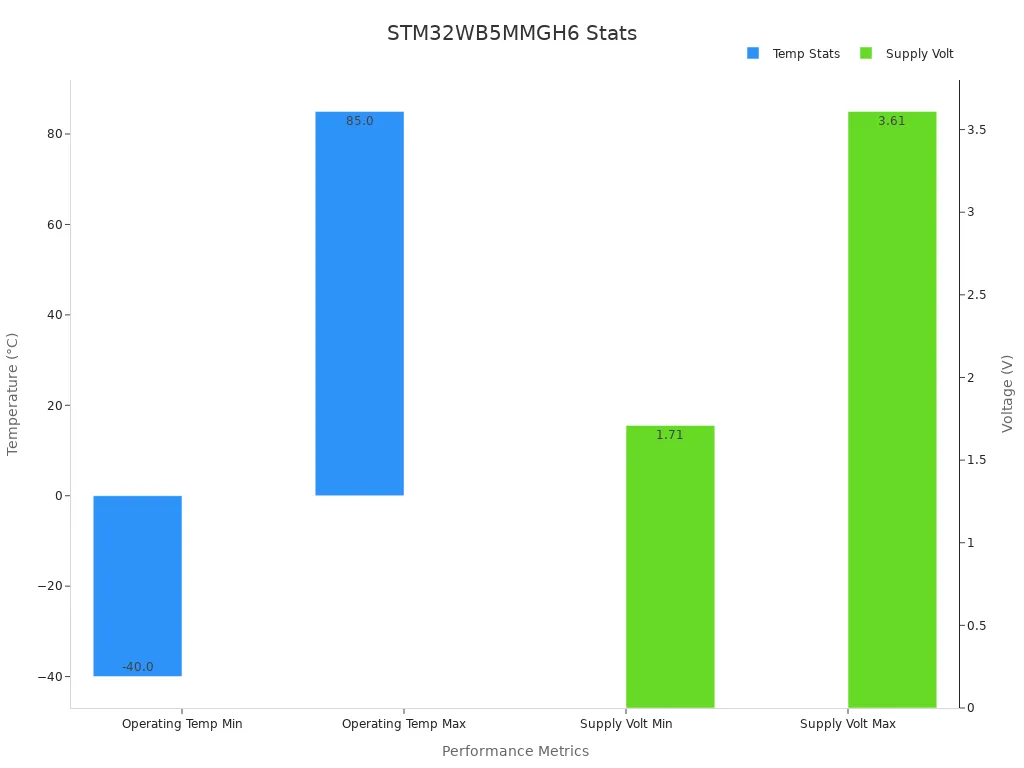
These features make the STM32WB5MMGH6 a powerful tool for developers looking to build reliable and efficient IoT solutions.
Applications of the STM32WB5MMGH6 in IoT and embedded systems
The STM32WB5MMGH6 module is a versatile solution for a wide range of IoT and embedded system applications. Its dual-core architecture and wireless capabilities make it suitable for the following use cases:
Smart home devices: Use the module to create smart lighting systems, thermostats, or security cameras. Its Bluetooth and Zigbee support ensures seamless integration with existing smart home ecosystems.
Wearable technology: The ultra-low power microcontroller design makes it ideal for fitness trackers, smartwatches, and health monitoring devices.
Industrial IoT: Leverage its robust design and long-range communication for industrial automation, asset tracking, and predictive maintenance systems.
Healthcare devices: Develop wireless medical devices like glucose monitors or pulse oximeters that require reliable and energy-efficient communication.
Prototyping and development: The micromod ecosystem simplifies the process of creating and testing new ideas. You can use micromod carrier boards to quickly prototype your designs.
By combining advanced wireless features with energy efficiency, the STM32WB5MMGH6 empowers you to build innovative solutions across various industries.
Required Tools and Materials
Essential hardware for the STM32WB5MMGH6
To get started with the STM32WB5MMGH6, you need a few essential hardware components. These tools help you connect, program, and test the module effectively. Here’s what you’ll need:
A MicroMod STM32WB5MMG processor. This 32-bit microcontroller is the core of your project and integrates seamlessly into the MicroMod ecosystem.
A compatible MicroMod carrier board. This board allows you to connect the processor to peripherals like sensors, LEDs, and buttons.
Debuggers and programmers, such as the ST-LINK/V2 or ST-LINK/V3, to upload and debug your code.
A reliable power supply to ensure stable operation of the module.
Additional peripherals like LEDs, buttons, and sensors for prototyping and testing.
You can also use a development kit, such as the STM32 Nucleo board, to evaluate the module’s capabilities. These kits simplify the setup process and provide a solid foundation for your projects.
Recommended software tools for STM32 development
The right software tools are crucial for programming and configuring the STM32WB5MMG. Here are the recommended tools:
STM32CubeIDE: An integrated development environment (IDE) for writing, compiling, and debugging your code.
STM32CubeMX: A graphical configurator that simplifies the setup of peripherals and middleware.
Wireless connectivity software, including Bluetooth and Zigbee stacks, to enable communication features.
Embedded software packages like HAL (Hardware Abstraction Layer) and LL (Low-Layer APIs) for efficient coding.
Partner tools and services, which expand the STM32 ecosystem and provide additional resources for development.
These tools streamline the development process and ensure compatibility with the STM32WB5MMGH6 module.
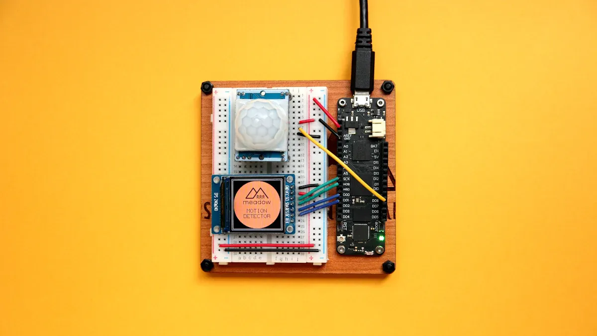
Using the MicroMod STM32WB5MMG processor for prototyping
The MicroMod STM32WB5MMG processor is a game-changer for prototyping. It fits into the MicroMod ecosystem, allowing you to swap processors without redesigning your project. This flexibility saves time and effort during development.
To start prototyping, insert the processor into a MicroMod carrier board. Connect peripherals like sensors or displays to the carrier board’s ports. Use Arduino-compatible tools to program the processor, making it easier to integrate with existing projects. The MicroMod ecosystem also supports various carrier boards, enabling you to test different configurations effortlessly.
By combining the STM32WB5MMG with the MicroMod ecosystem, you can quickly prototype and iterate on your designs. This approach accelerates the development of IoT and embedded system projects.
Setting Up the STM32WB5MMGH6 Hardware
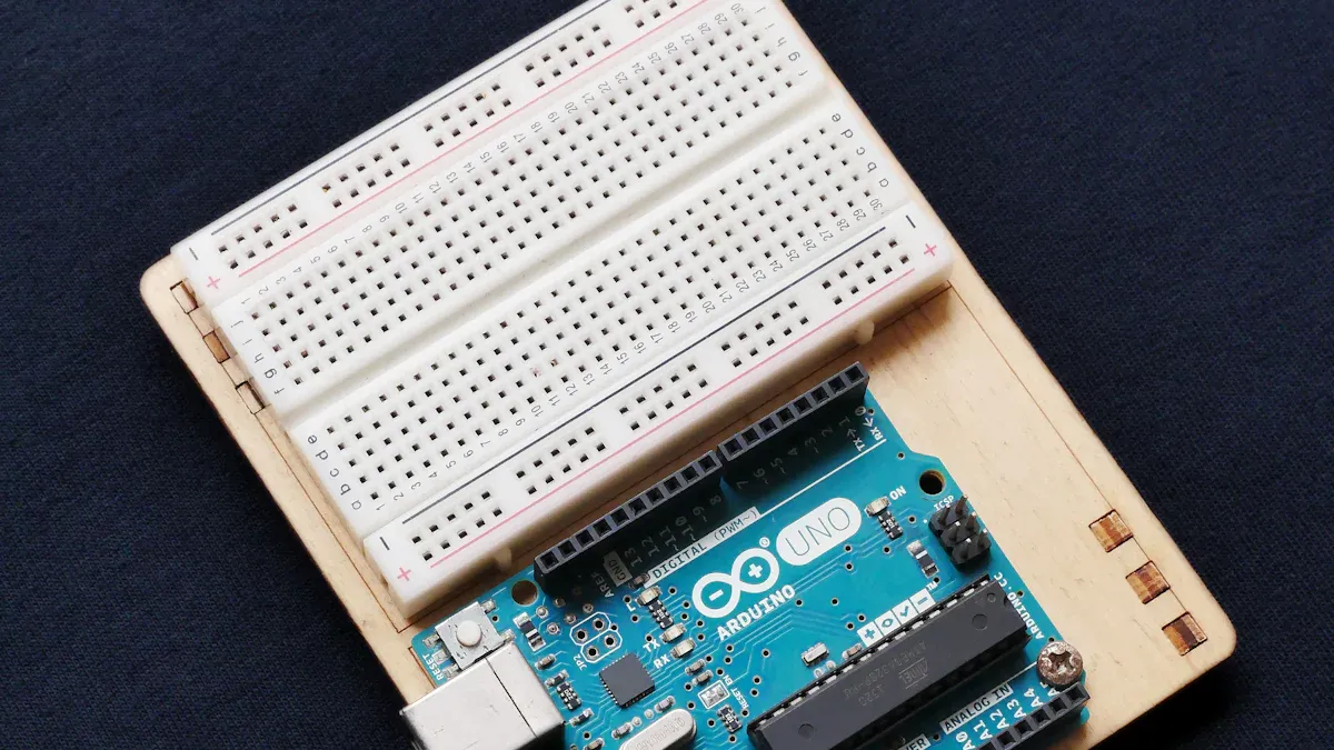
Connecting the STM32WB5MMGH6 to a development board
To begin, you need to connect the stm32wb5mmg module to a development board. The micromod ecosystem simplifies this process. Start by inserting the micromod stm32wb5mmg processor into a compatible micromod carrier board. Align the processor’s pins with the designated slots on the carrier board. Once aligned, press it gently into place to ensure a secure connection.
The carrier board provides access to essential interfaces like GPIO pins, power inputs, and communication ports. These GPIO pins allow you to connect peripherals such as sensors, LEDs, and buttons. Use jumper wires to link the GPIO pins to your desired components. This setup ensures that the stm32wb5mmg module can interact with external devices effectively.
Powering the STM32WB5MMGH6 module
Powering the stm32wb5mmg module is straightforward. The micromod carrier board typically includes a power input port. You can use a USB cable to supply power through this port. Alternatively, connect an external power source that matches the module’s voltage requirements (1.71 V to 3.6 V).
Ensure the power supply is stable to avoid damaging the module. Many carrier boards also feature onboard voltage regulators, which help maintain consistent power levels. Once powered, the module’s status LED will light up, indicating that it is ready for use.
Adding peripherals like LEDs and buttons
Adding peripherals enhances the functionality of your stm32wb5mmg module. Start by connecting an LED to one of the GPIO pins on the micromod carrier board. Use a resistor in series with the LED to prevent excessive current flow. Similarly, you can attach a button to another GPIO pin.
When wiring these components, ensure that the GPIO pins are configured correctly in your software. For example, set the pin connected to the LED as an output and the pin linked to the button as an input. This configuration allows you to control the LED and read the button’s state through your code.
By integrating peripherals, you can test and expand your project’s capabilities, making the stm32wb5mmg module a versatile tool for development.
Configuring the STM32WB5MMGH6 Software
Installing STM32CubeMX and STM32CubeIDE
To start programming the STM32WB5MMGH6 module, you need to install and use STM32CubeMX and STM32CubeIDE. These tools simplify the configuration and coding process. Begin by downloading STM32CubeMX from STMicroelectronics' official website. This graphical tool helps you set up the peripherals and middleware for your project. Once downloaded, follow the installation steps provided on the website.
Next, install STM32CubeIDE. This integrated development environment combines coding, compiling, and debugging into one platform. It works seamlessly with STM32 processors, including the STM32WB5MMGH6. After installation, launch STM32CubeIDE and connect your MicroMod carrier board to your computer. This setup ensures you can start writing code immediately.
Tip: If you're familiar with installing Arduino IDE, you'll find the process for STM32CubeMX and STM32CubeIDE straightforward.
Setting up the development environment
Setting up the development environment involves configuring STM32CubeMX and STM32CubeIDE to work with your STM32WB5MMGH6 module. Open STM32CubeMX and select the STM32WB5MMGH6 processor from the list of supported devices. Use the graphical interface to enable peripherals like GPIO, UART, and SPI. You can also configure wireless features such as Bluetooth and Zigbee directly within the tool.
Export the configuration to STM32CubeIDE. This step generates the necessary code framework for your project. Open the exported project in STM32CubeIDE and verify the settings. You can now write and debug your code using the IDE's built-in tools.
Note: STM32CubeMX provides a clear overview of your processor's capabilities, making it easier to optimize your project.
Configuring wireless features like Bluetooth and Zigbee
The STM32WB5MMGH6 module supports advanced wireless features, including Bluetooth and Zigbee. To enable these features, use STM32CubeMX. Start by selecting the wireless protocol you want to use. For Bluetooth, enable the BLE stack and configure the parameters such as device name and connection interval. For Zigbee, activate the Zigbee stack and set up the network parameters.
Once configured, export the settings to STM32CubeIDE. Write the code to initialize the wireless features. For example, use the HAL library to set up Bluetooth communication. Test the wireless functionality by connecting your module to a compatible device. This process ensures your STM32WB5MMGH6 module is ready for IoT applications.
Tip: The STM32WB5MMGH6's dual-core arm architecture allows you to run wireless tasks on one core while handling application logic on the other.
First Project with the STM32WB5MMGH6
Writing a basic LED blinking program
Creating a basic LED blinking program is an excellent way to start your journey with the STM32WB5MMGH6 module. This simple project helps you understand how to control GPIO pins and interact with external components. To begin, you need to connect an LED to one of the GPIO pins on your MicroMod carrier board. Use a resistor in series with the LED to limit the current and protect the circuit.
Once the hardware is ready, open your development environment. If you are using the Arduino IDE, you can follow the MicroMod STM32WB5MMG Hookup Guide. This guide provides a step-by-step example of how to create a blinking LED program. It includes details on setting up the hardware and configuring the software. The example uses straightforward code to toggle the LED on and off at regular intervals.
Here’s a sample code snippet to get you started:
void setup() {
  pinMode(LED_BUILTIN, OUTPUT); // Set the LED pin as an output
}

void loop() {
  digitalWrite(LED_BUILTIN, HIGH); // Turn the LED on
  delay(1000);                     // Wait for 1 second
  digitalWrite(LED_BUILTIN, LOW);  // Turn the LED off
  delay(1000);                     // Wait for 1 second
}
This code initializes the LED pin as an output in the setup() function. The loop() function alternates the LED state between on and off, with a one-second delay between each change. You can modify the delay values to adjust the blinking speed.
Tip: Always double-check your connections and ensure the LED is connected to the correct GPIO pin specified in your code.
Uploading code to the STM32WB5MMGH6
After writing the code, the next step is to upload it to the STM32WB5MMGH6 module. Connect your MicroMod carrier board to your computer using a USB cable. Ensure that the board is powered and recognized by your computer. Open your development environment and select the correct board and port settings. For example, in the Arduino IDE, choose the MicroMod STM32WB5MMG processor from the board menu.
Click the upload button to transfer the code to the module. The IDE will compile the code and send it to the STM32WB5MMGH6. During this process, you may see status messages indicating the progress. If the upload is successful, the IDE will display a confirmation message.
Note: If you encounter errors during the upload, check the board settings and ensure the correct drivers are installed on your computer.
Testing and verifying the program output
Once the code is uploaded, it’s time to test your project. Observe the LED connected to the STM32WB5MMGH6 module. It should start blinking at the interval specified in your code. If the LED does not blink, verify the connections and ensure the GPIO pin matches the one defined in the code.
You can also use debugging tools like the serial monitor in the Arduino IDE to check for errors or monitor the program’s behavior. Add Serial.print() statements to your code to display messages or variable values. This approach helps you identify issues and confirm that the program is running as expected.
Tip: Experiment with different delay values in your code to see how they affect the LED’s blinking speed. This hands-on approach enhances your understanding of timing and GPIO control.
By completing this project, you gain practical experience with the STM32WB5MMGH6 module. This foundational knowledge prepares you for more complex projects involving sensors, wireless communication, and advanced features.
Debugging and Troubleshooting the STM32WB5MMGH6
Resolving common hardware issues
When working with the STM32WB5MMGH6 module, you might encounter hardware-related challenges. These issues often stem from improper connections, power supply problems, or faulty components. Start by checking all connections on your development board. Ensure the module is securely seated in the MicroMod carrier board and that all GPIO pins are correctly wired to peripherals like LEDs or buttons.
Verify the power supply. Use a multimeter to confirm that the voltage matches the module's requirements (1.71 V to 3.6 V). If the module does not power on, inspect the USB cable or external power source for defects. Additionally, check the status LED on the carrier board. A lit LED usually indicates proper power delivery.
If peripherals fail to respond, test them individually. For example, connect an LED directly to a power source to confirm it works. Replace any non-functional components before proceeding. These steps help you identify and resolve hardware issues efficiently.
Debugging code with STM32CubeIDE
STM32CubeIDE provides powerful tools for debugging your code. Begin by enabling the debugging mode in the IDE. Connect your development board to your computer using a USB cable. Select the STM32WB5MMGH6 module as the target device in the IDE settings.
Use breakpoints to pause the program at specific lines of code. This feature allows you to examine variable values and program flow. For example, if your LED blinking program does not work, set a breakpoint in the loop function. Check whether the code reaches the LED control commands.
The IDE also includes a step-by-step execution feature. Use it to run your code one line at a time. This method helps you pinpoint errors in logic or syntax. By leveraging these tools, you can streamline the process of coding and debugging.
Fixing wireless connectivity problems
Wireless connectivity issues can disrupt your project. To fix these problems, start by verifying the wireless settings in STM32CubeMX. Ensure the correct protocol, such as Bluetooth or Zigbee, is enabled. Double-check parameters like device name, connection interval, and network ID.
If the module fails to connect to other devices, test the signal strength. Use a spectrum analyzer to measure the signal and identify interference sources. Move the module away from potential disruptors like Wi-Fi routers or metal objects.
Update the firmware if connectivity issues persist. Download the latest firmware from STMicroelectronics' website and follow the update instructions. This step often resolves compatibility problems and improves performance. By addressing these factors, you can ensure reliable wireless communication.
Exploring Advanced Features of the STM32WB5MMGH6
Using the dual-core architecture for multitasking
The STM32WB5MMGH6 module’s dual-core architecture is a game-changer for multitasking. It features two processors: an Arm Cortex-M4 for application tasks and an Arm Cortex-M0+ dedicated to managing wireless communication. This separation allows you to run complex applications while maintaining seamless wireless connectivity. For example, you can process sensor data on one core while the other handles Bluetooth or Zigbee communication.
This architecture also supports concurrent execution of wireless protocols like Bluetooth LE 5.4 and 802.15.4. You can use this feature to build devices that communicate with multiple networks simultaneously. Additionally, the module enables secure Over-The-Air (OTA) updates, ensuring your device stays up-to-date without interrupting its primary functions.
| Feature | Description |
|---|---|
| Architecture | Dual-core architecture enhances multitasking capabilities. |
| Wireless Protocols | Supports concurrent execution of Bluetooth LE 5.4 and 802.15.4 protocols. |
| OTA Updates | Enables secured Over-The-Air updates for future-proofing. |
Implementing Bluetooth Low Energy 5.4
The STM32WB5MMGH6 module excels in Bluetooth Low Energy (BLE) 5.4 implementation. BLE 5.4 offers improved data rates, extended range, and lower power consumption, making it ideal for IoT applications. With a transmission power of up to +6 dBm and a receiver sensitivity of -96 dBm, the module ensures reliable communication over distances up to 75 meters. These features make it perfect for smart home devices, wearables, and healthcare applications.
The module also includes advanced security features like AES 256-bit encryption and secure firmware updates. These ensure your Bluetooth-enabled devices remain safe from potential threats.
| Specification | Value |
|---|---|
| Tx output power | Up to +6 dBm |
| Rx sensitivity | -96 dBm (BLE at 1 Mbps) |
| Range | Up to 75 meters |
| Security features | AES 256-bit, secure firmware |
Leveraging Zigbee 3.0 for IoT applications
Zigbee 3.0 support in the STM32WB5MMGH6 module opens up new possibilities for IoT applications. Zigbee’s mesh networking capability allows devices to communicate over long distances by relaying data through intermediate nodes. This feature is particularly useful in smart lighting systems, industrial automation, and energy management.
The module’s high receiver sensitivity of -100 dBm ensures stable communication even in challenging environments. Its compliance with certifications like CE and FCC guarantees reliability and safety for your projects. By leveraging Zigbee 3.0, you can create scalable and energy-efficient IoT networks.
You’ve now completed the setup and created your first project with the STM32WB5MMGH6 module. From connecting hardware to writing a basic LED blinking program, you’ve gained hands-on experience with this versatile tool. This foundational knowledge prepares you to explore advanced features like Bluetooth and Zigbee integration.
Take the next step by experimenting with more complex projects. Use the dual-core architecture to handle multitasking or implement wireless communication for IoT applications. The STM32WB5MMGH6 offers endless possibilities for innovation and development.
Tip: Keep experimenting with new ideas to unlock the full potential of your projects.
FAQ
What makes the STM32WB5MMGH6 module beginner-friendly?
The STM32WB5MMGH6 simplifies development with pre-certified wireless stacks, an integrated RF design, and compatibility with the MicroMod ecosystem. These features reduce setup complexity and allow you to focus on learning and building projects.
Can I use the STM32WB5MMGH6 for battery-powered devices?
Yes! The module’s ultra-low power design ensures energy efficiency, making it ideal for battery-operated devices like wearables, sensors, and portable IoT gadgets.
How do I update the firmware on the STM32WB5MMGH6?
Use STM32CubeProgrammer to update the firmware. Connect your module via USB, select the firmware file, and follow the on-screen instructions. Always download firmware updates from trusted sources like STMicroelectronics.
What wireless protocols does the STM32WB5MMGH6 support?
The module supports Bluetooth Low Energy 5.4, Zigbee 3.0, OpenThread, and 802.15.4. These protocols make it versatile for IoT applications, including smart homes, industrial automation, and healthcare devices.
Do I need advanced coding skills to use the STM32WB5MMGH6?
No, you don’t. Tools like STM32CubeMX and STM32CubeIDE simplify coding and configuration. Tutorials and example projects help you get started, even if you’re new to embedded systems.
Tip: Start with simple projects like LED blinking to build confidence before exploring advanced features.
Specifications
- TypeParameter
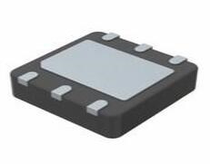
- Package / Case
refers to the protective housing that encases an electronic component, providing mechanical support, electrical connections, and thermal management.
4-SMD, No Lead - Mounting Type
The "Mounting Type" in electronic components refers to the method used to attach or connect a component to a circuit board or other substrate, such as through-hole, surface-mount, or panel mount.
Surface Mount - Product StatusActive
- MfrEPSON
- Base Product Number
"Base Product Number" (BPN) refers to the fundamental identifier assigned to a component by the manufacturer. This number is used to identify a specific product family or series of components that share common features, characteristics, or functionality. The BPN is usually part of a larger part number or order code that includes additional information, such as variations in packaging, tolerance, voltage ratings, and other specifications.
SG-8101 - PackageTape & Reel (TR)
- Series
In electronic components, the "Series" refers to a group of products that share similar characteristics, designs, or functionalities, often produced by the same manufacturer. These components within a series typically have common specifications but may vary in terms of voltage, power, or packaging to meet different application needs. The series name helps identify and differentiate between various product lines within a manufacturer's catalog.
SG-8101 - Operating Temperature
The operating temperature is the range of ambient temperature within which a power supply, or any other electrical equipment, operate in. This ranges from a minimum operating temperature, to a peak or maximum operating temperature, outside which, the power supply may fail.
-40°C ~ 105°C - Size / Dimension
In electronic components, the parameter "Size / Dimension" refers to the physical dimensions of the component, such as its length, width, and height. These dimensions are crucial for determining how the component will fit into a circuit or system, as well as for ensuring compatibility with other components and the overall design requirements. The size of a component can also impact its performance characteristics, thermal properties, and overall functionality within a given application. Engineers and designers must carefully consider the size and dimensions of electronic components to ensure proper integration and functionality within their designs.
0.197 L x 0.126 W (5.00mm x 3.20mm) - TypeXO (Standard)
- Voltage - Supply
Voltage - Supply refers to the range of voltage levels that an electronic component or circuit is designed to operate with. It indicates the minimum and maximum supply voltage that can be applied for the device to function properly. Providing supply voltages outside this range can lead to malfunction, damage, or reduced performance. This parameter is critical for ensuring compatibility between different components in a circuit.
1.8V ~ 3.3V - Frequency
In electronic components, the parameter "Frequency" refers to the rate at which a signal oscillates or cycles within a given period of time. It is typically measured in Hertz (Hz) and represents how many times a signal completes a full cycle in one second. Frequency is a crucial aspect in electronic components as it determines the behavior and performance of various devices such as oscillators, filters, and communication systems. Understanding the frequency characteristics of components is essential for designing and analyzing electronic circuits to ensure proper functionality and compatibility with other components in a system.
36.8182 MHz - Frequency Stability
the variation of output frequency of a crystal oscillator due to external conditions like temperature variation, voltage variation, output load variation, and frequency aging.
±20ppm - Output
In electronic components, the parameter "Output" typically refers to the signal or data that is produced by the component and sent to another part of the circuit or system. The output can be in the form of voltage, current, frequency, or any other measurable quantity depending on the specific component. The output of a component is often crucial in determining its functionality and how it interacts with other components in the circuit. Understanding the output characteristics of electronic components is essential for designing and troubleshooting electronic circuits effectively.
CMOS - Function
The parameter "Function" in electronic components refers to the specific role or purpose that the component serves within an electronic circuit. It defines how the component interacts with other elements, influences the flow of electrical signals, and contributes to the overall behavior of the system. Functions can include amplification, signal processing, switching, filtering, and energy storage, among others. Understanding the function of each component is essential for designing effective and efficient electronic systems.
Standby (Power Down) - Base Resonator
Base resonator is a component used in electronic circuits to establish a specific resonant frequency. It typically consists of a combination of inductors and capacitors that create a resonant LC circuit. The primary function of a base resonator is to filter signals, allowing certain frequencies to pass while attenuating others. This makes it essential in applications like radio transmitters and receivers where precise frequency selection is critical.
Crystal - Current - Supply (Max)
The parameter "Current - Supply (Max)" in electronic components refers to the maximum amount of current that a component can draw from a power supply for its operation. This parameter is critical for ensuring that the power supply can adequately meet the demands of the component without causing damage or malfunction. Exceeding this specified maximum current can lead to overheating, reduced performance, or failure of the component. It is essential to consider this value when designing or integrating components into electronic circuits to maintain reliability and functionality.
6.8mA (Typ) - Current - Supply (Disable) (Max)
The parameter "Current - Supply (Disable) (Max)" refers to the maximum current that an electronic component will draw from the supply when it is in a disabled or inactive state. This parameter is critical for power management, as it helps designers understand the power consumption of the component when it is not performing its primary function. Lower values for this parameter are generally preferred in battery-powered or energy-sensitive applications to minimize power waste.
1.1µA - Spread Spectrum Bandwidth
In telecommunication and radio communication, spread-spectrum techniques are methods by which a signal (e.g., an electrical, electromagnetic, or acoustic signal) generated with a particular bandwidth is deliberately spread in the frequency domain, resulting in a signal with a wider bandwidth.
- - Absolute Pull Range (APR)
The Absolute Pull Range (APR) is a parameter used in electronic components, particularly in devices such as crystal oscillators and resonators. It refers to the maximum allowable frequency deviation that can occur due to external factors such as temperature variations, voltage fluctuations, or mechanical stress. The APR value indicates the range within which the component can operate reliably without experiencing significant frequency shifts that could affect its performance. Manufacturers specify the APR to ensure that the component meets the required frequency stability under various operating conditions, helping designers select the appropriate component for their application.
- - Height Seated (Max)
Height Seated (Max) is a parameter in electronic components that refers to the maximum allowable height of the component when it is properly seated or installed on a circuit board or within an enclosure. This specification is crucial for ensuring proper fit and alignment within the overall system design. Exceeding the maximum seated height can lead to mechanical interference, electrical shorts, or other issues that may impact the performance and reliability of the electronic device. Manufacturers provide this information to help designers and engineers select components that will fit within the designated space and function correctly in the intended application.
0.051 (1.30mm) - Ratings
The parameter "Ratings" in electronic components refers to the specified limits that define the maximum operational capabilities of a component. These ratings include voltage, current, power, temperature, and frequency, determining the conditions under which the component can function safely and effectively. Exceeding these ratings can lead to failure, damage, or unsafe operation, making it crucial for designers to adhere to them during component selection and usage.
-
Datasheet PDF
- Datasheets :
 Mastering 50-MHz Switching: LMG1210 GaN FET Driver Specs, Layout Tips, and Alternatives
11 March 2026276
 LD39200PUR Ultra Low Drop Linear Regulator: 2A, 6DFN, LD39200PUR Datasheet
22 January 20221840
 J201 Transistor: JFET N-Channel, Pinout, Datasheet, Equivalent
12 January 20229266
 STM32G070CBT6: Overview, Features, and Datasheet
11 December 20232600
 STM32H723VGT6 Datasheet Guide: How to Find & Interpret Technical Documentation
05 July 20251982
 LSM9DS1TR Acceleration Sensor: Pinout, Datasheet, and Application Circuit
12 July 20211290
 SN74LVC2G17DCKR Dual Schmitt-Trigger Buffer: Circuit, Pinout, and Datasheet
29 March 20223141
 A Comprehensive Guide to S-24CS64A0I-J8T1G EEPROM Memory Module
07 March 2024439
 What is Inter-Integrated Circuit (I2C)?
23 February 20223453
 Role of Direct Memory Access in Modern Computing
12 November 20244761
 Introduction to Lead Acid Battery: Construction, Working Principle and Types
04 March 202110212
 Foxconn Announces Investment of $9 Billion to Build a Chip Factory in Saudi Arabia
15 March 20227181
 Basic Introduction to RF Connector
30 October 20258067
 Bearing: Features, Types and Uses
08 February 20229773
 What is SERDES?
04 November 202123627
 What are the Types and Dielectric of Ceramic Capacitors?
16 October 202512123
STMicroelectronics
In Stock
United States
China
Canada
Japan
Russia
Germany
United Kingdom
Singapore
Italy
Hong Kong(China)
Taiwan(China)
France
Korea
Mexico
Netherlands
Malaysia
Austria
Spain
Switzerland
Poland
Thailand
Vietnam
India
United Arab Emirates
Afghanistan
Åland Islands
Albania
Algeria
American Samoa
Andorra
Angola
Anguilla
Antigua & Barbuda
Argentina
Armenia
Aruba
Australia
Azerbaijan
Bahamas
Bahrain
Bangladesh
Barbados
Belarus
Belgium
Belize
Benin
Bermuda
Bhutan
Bolivia
Bonaire, Sint Eustatius and Saba
Bosnia & Herzegovina
Botswana
Brazil
British Indian Ocean Territory
British Virgin Islands
Brunei
Bulgaria
Burkina Faso
Burundi
Cabo Verde
Cambodia
Cameroon
Cayman Islands
Central African Republic
Chad
Chile
Christmas Island
Cocos (Keeling) Islands
Colombia
Comoros
Congo
Congo (DRC)
Cook Islands
Costa Rica
Côte d’Ivoire
Croatia
Cuba
Curaçao
Cyprus
Czechia
Denmark
Djibouti
Dominica
Dominican Republic
Ecuador
Egypt
El Salvador
Equatorial Guinea
Eritrea
Estonia
Eswatini
Ethiopia
Falkland Islands
Faroe Islands
Fiji
Finland
French Guiana
French Polynesia
Gabon
Gambia
Georgia
Ghana
Gibraltar
Greece
Greenland
Grenada
Guadeloupe
Guam
Guatemala
Guernsey
Guinea
Guinea-Bissau
Guyana
Haiti
Honduras
Hungary
Iceland
Indonesia
Iran
Iraq
Ireland
Isle of Man
Israel
Jamaica
Jersey
Jordan
Kazakhstan
Kenya
Kiribati
Kosovo
Kuwait
Kyrgyzstan
Laos
Latvia
Lebanon
Lesotho
Liberia
Libya
Liechtenstein
Lithuania
Luxembourg
Macao(China)
Madagascar
Malawi
Maldives
Mali
Malta
Marshall Islands
Martinique
Mauritania
Mauritius
Mayotte
Micronesia
Moldova
Monaco
Mongolia
Montenegro
Montserrat
Morocco
Mozambique
Myanmar
Namibia
Nauru
Nepal
New Caledonia
New Zealand
Nicaragua
Niger
Nigeria
Niue
Norfolk Island
North Korea
North Macedonia
Northern Mariana Islands
Norway
Oman
Pakistan
Palau
Palestinian Authority
Panama
Papua New Guinea
Paraguay
Peru
Philippines
Pitcairn Islands
Portugal
Puerto Rico
Qatar
Réunion
Romania
Rwanda
Samoa
San Marino
São Tomé & Príncipe
Saudi Arabia
Senegal
Serbia
Seychelles
Sierra Leone
Sint Maarten
Slovakia
Slovenia
Solomon Islands
Somalia
South Africa
South Sudan
Sri Lanka
St Helena, Ascension, Tristan da Cunha
St. Barthélemy
St. Kitts & Nevis
St. Lucia
St. Martin
St. Pierre & Miquelon
St. Vincent & Grenadines
Sudan
Suriname
Svalbard & Jan Mayen
Sweden
Syria
Tajikistan
Tanzania
Timor-Leste
Togo
Tokelau
Tonga
Trinidad & Tobago
Tunisia
Turkey
Turkmenistan
Turks & Caicos Islands
Tuvalu
U.S. Outlying Islands
U.S. Virgin Islands
Uganda
Ukraine
Uruguay
Uzbekistan
Vanuatu
Vatican City
Venezuela
Wallis & Futuna
Yemen
Zambia
Zimbabwe
![STM32F103RBT6]() STM32F103RBT6
STM32F103RBT6STMicroelectronics
![STM32F103ZET6]() STM32F103ZET6
STM32F103ZET6STMicroelectronics
![STM32H743IIT6]() STM32H743IIT6
STM32H743IIT6STMicroelectronics
![STM32F407VET6]() STM32F407VET6
STM32F407VET6STMicroelectronics
![STM32F405RGT6]() STM32F405RGT6
STM32F405RGT6STMicroelectronics
![STM32F030C8T6]() STM32F030C8T6
STM32F030C8T6STMicroelectronics
![STM32F100C8T6B]() STM32F100C8T6B
STM32F100C8T6BSTMicroelectronics
![STM32F103VBT6]() STM32F103VBT6
STM32F103VBT6STMicroelectronics
![STM8S003F3U6TR]() STM8S003F3U6TR
STM8S003F3U6TRSTMicroelectronics
![STM32F429ZIT6]() STM32F429ZIT6
STM32F429ZIT6STMicroelectronics


