
Guide to Reading the Toshiba 74HC245D Datasheet


Understand the Toshiba 74HC245D datasheet: pinout, features, specs, and tips for using this 8-bit bus transceiver in digital circuit designs.
Product Introduction
Understanding datasheets helps you make the most of digital ICs like the Toshiba 74HC245D. Many engineers, students, and hobbyists find it tough to work with modern electronics because surface-mount ICs and tiny components limit hands-on learning. You often face challenges such as confusing datasheet formats, misleading feature sections, or unclear ratings. Building strong datasheet skills lets you confidently select and configure parts for your projects.
Modern electronics use surface-mount ICs, making physical access difficult.
Variability in datasheets can cause confusion, so careful reading is essential.
Toshiba 74HC245D Overview
Device Summary
You often need to connect different parts of a digital system. The Toshiba 74HC245D helps you do this with ease. This chip belongs to the 74HCxxxD series of CMOS logic ICs. It works as an octal bus transceiver, which means it can send and receive data on eight lines at once. The device uses high-speed CMOS technology, so it runs fast and uses little power. You can use it with logic levels up to 6V, making it flexible for many projects.
Tip: The 74HC245D supports surface-mount SOIC packages. This makes it a good choice for modern, compact circuit boards.
Here are some important features:
8-bit bidirectional data transfer
3-state outputs for easy bus sharing
Non-inverting logic for simple signal flow
Wide operating voltage range (2V to 6V)
Low power consumption
You can use the Toshiba 74HC245D to buffer, latch, or shift voltage levels between different parts of your circuit. It works well in both industrial and home electronics.
| Feature | Toshiba 74HC245D | STMicro M74HC245B1 |
|---|---|---|
| Operating Voltage Range | 2.0 V to 6.0 V | 2.0 V to 6.0 V |
| Packaging Type | Surface mount (SOIC) | Through-hole (DIP20) |
| Output Current | Approx. 8 mA | Approx. 7.8 mA |
| Power Consumption | Low | Low |
| Special Features | 3-state, bidirectional | 3-state, bidirectional |
Applications
You will find the Toshiba 74HC245D in many digital systems. It helps you move data between microcontrollers, memory chips, and other devices. Here are some common uses:
Connect microcontrollers to peripherals or extra memory.
Control address and data buses in microprocessor systems.
Share data lines between different sources and destinations.
Enable two-way data transfers between circuit blocks.
Shift voltage levels when working with different logic voltages.
Manage data flow on system buses in computers and embedded systems.
The chip’s bidirectional transfer and tri-state outputs let you build flexible and reliable circuits. You can use it in multiplexers, communication links, and bus management tasks. Its speed and low power draw make it a strong choice for both new and existing designs.
Pin Configuration
Pinout
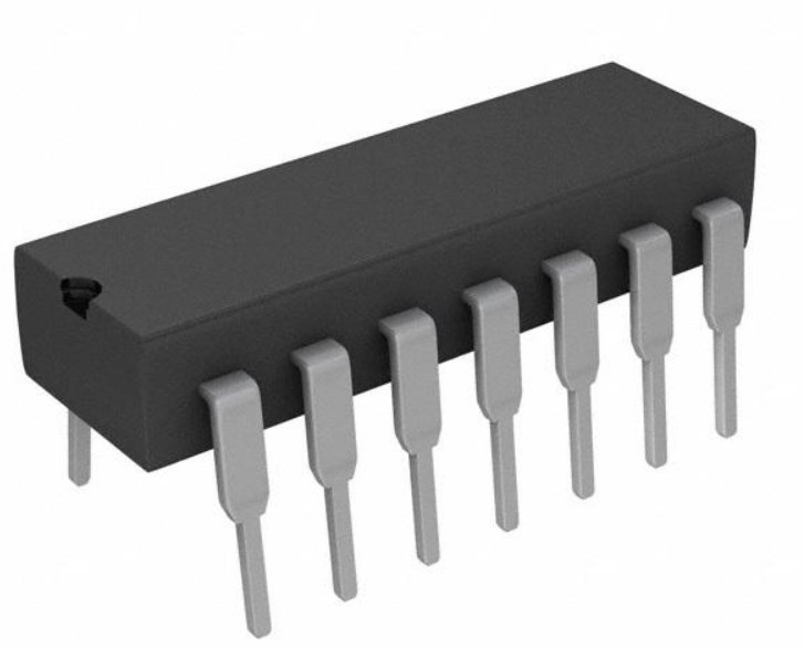
When you look at the Toshiba 74HC245D, you see a total of 20 pins. Each pin has a specific job. The chip uses two sets of data pins, labeled A0–A7 and B0–B7. These pins connect to two different buses. You also find two important control pins: DIR and OE. The DIR pin sits at pin 1, and the OE pin sits at pin 19. The remaining pins are for power (Vcc) and ground (GND).
Here is a simple pinout table for the SOIC-20 package:
| Pin Number | Pin Name | Description |
|---|---|---|
| 1 | DIR | Direction Control |
| 2–9 | A0–A7 | Data Bus A |
| 10 | GND | Ground |
| 11–18 | B0–B7 | Data Bus B |
| 19 | OE | Output Enable |
| 20 | Vcc | Power Supply |
Tip: Always double-check the pinout before wiring the chip. This helps you avoid mistakes that could damage your circuit.
Pin Functions
Each pin on the Toshiba 74HC245D plays a key role in how the chip works. The DIR and OE pins control the main functions of the device.
| Pin | Function Description |
|---|---|
| DIR (Pin 1) | Controls the direction of data flow between bus A and bus B, determining whether data moves from A to B or B to A. |
| OE (Pin 19) | Output Enable pin; when low, outputs are enabled allowing data transmission; when high, outputs enter a high-impedance state, effectively disconnecting the transceiver from the bus to prevent interference. |
You use the DIR pin to set the direction of data transfer. When DIR is high, data moves from the A bus to the B bus. When DIR is low, data moves from the B bus to the A bus. The OE pin controls whether the outputs are active. If you set OE low, the outputs work normally. If you set OE high, the outputs go into a high-impedance state. This means the chip disconnects from the bus, so other devices can use it without interference.
The Toshiba 74HC245D supports bidirectional data transfer. You can send data in both directions between bus A and bus B. The DIR pin lets you choose the direction. The chip also features tri-state outputs. This means each output can be high, low, or in a high-impedance state. The OE pin controls this feature. Tri-state outputs allow you to connect several chips to the same bus. Only one chip drives the bus at a time, so you avoid conflicts.
You can:
Transfer data from A to B or B to A, depending on DIR.
Enable or disable the outputs using OE.
Connect multiple devices to the same bus without interference, thanks to tri-state outputs.
This combination of bidirectional transfer and tri-state outputs makes the Toshiba 74HC245D very useful in digital systems. You can use it to manage data flow between different parts of your circuit, share buses, and prevent bus conflicts.
Features and Specifications
Key Features
You can use the Toshiba 74HC245D in many digital projects because it offers several important features. This chip supports fast and reliable data transfer between two buses. You get eight channels for data, which means you can move eight bits at once. The device uses CMOS technology, so it works quickly and does not use much power.
Here are some key features you should know:
Bidirectional Data Transfer: You can send data in both directions between bus A and bus B. The DIR pin lets you choose the direction.
Tri-State Outputs: The outputs can be high, low, or disconnected (high-impedance). This feature allows you to connect several chips to the same bus without causing problems.
Wide Voltage Range: The chip works with supply voltages from 2.0V to 6.0V. You can use it in many different circuits.
High Output Drive: Each output can handle up to 24 mA. This means you can drive LEDs or other loads directly.
Low Power Consumption: The chip uses very little power, which helps your projects run cooler and last longer.
Fast Switching: The device responds quickly to changes in input, so you can use it in high-speed circuits.
Surface-Mount Package: The SOIC-20 package makes it easy to use on modern circuit boards.
💡 Tip: You can use the Toshiba 74HC245D to connect microcontrollers, memory chips, or other digital devices that need to share data.
Electrical Specs
You need to understand the electrical specifications before you add this chip to your design. These values tell you how much voltage and current the chip can handle, and what temperatures it can work in. Always check these numbers to make sure your circuit will work safely.
Here is a table that shows the main electrical ratings for the Toshiba 74HC245D:
| Parameter | Minimum Value | Maximum Value | Unit |
|---|---|---|---|
| Supply Voltage (Vcc) | 2.0 | 6.0 | Volts |
| Output Current (High/Low) | 7.8 | 7.8 | mA |
| Output Current (source/sink) | N/A | 24 | mA |
| Operating Temperature | -40 | 125 | °C |
You can see that the chip works with supply voltages from 2.0V up to 6.0V. Each output can provide up to 7.8 mA in normal operation, but the absolute maximum output current is 24 mA. This means you should keep your design within the normal range for best results. The chip can operate in temperatures from -40°C to 125°C. This wide range makes it suitable for both indoor and outdoor projects.
⚠️ Note: Always keep the chip within its recommended voltage and temperature limits. If you go beyond these values, you might damage the chip or cause it to stop working.
The Toshiba 74HC245D gives you flexibility and reliability. You can use it in many environments, from cold outdoor setups to warm indoor systems. The wide voltage and current ratings help you design safe and effective circuits.
Operation
Block Diagram
You can understand how the chip works by looking at its block diagram. The diagram shows two sets of data lines, labeled A0–A7 and B0–B7. Each set connects to a group of buffers inside the chip. The DIR pin controls the direction of data flow. The OE pin controls whether the outputs are active or in a high-impedance state.
The block diagram helps you see how signals move through the chip. It shows the connection between the control pins and the data paths.
Data flows from A to B when DIR is high.
Data flows from B to A when DIR is low.
OE disables all outputs when set high.
Logic Table
The logic table tells you what happens when you change the DIR and OE pins. You can use this table to predict the chip’s behavior in your circuit.
| OE | DIR | Data Flow | Output State |
|---|---|---|---|
| L | H | A → B | B outputs active |
| L | L | B → A | A outputs active |
| H | X | No transfer | High-impedance |
"L" means logic low (0).
"H" means logic high (1).
"X" means any value.
You can use this table to set up the chip for your needs. Set OE low to enable outputs. Set DIR to choose the direction.
Timing
Timing diagrams show how fast the chip responds to changes. You need to know these values to make sure your circuit works well. The chip has a propagation delay, which is the time it takes for a signal to travel from input to output.
Typical propagation delay: 8 ns at 5V.
Output enable/disable time: about 10 ns.
Always check the timing diagrams in the datasheet. They help you avoid errors in high-speed circuits.
The Toshiba 74HC245D works well in most digital systems. You can trust its timing for reliable data transfer.
Application Circuits
Typical Uses
You can use this chip in many digital projects. It helps you move data between two parts of a circuit. Here are some common ways you might see it used:
Acts as an 8-bit bidirectional data bus transceiver. You control the direction with the DIR pin and turn the outputs on or off with the OE pin.
Works as a logic level converter. You can connect a 3.3V microcontroller to a 5V device without damaging either part.
Supports communication protocols like SPI and I2C. The chip lets several devices share the same data lines by using its three-state outputs.
Connects two buses for asynchronous data transfer. You can send data from one side to the other when you need to.
Drives moderate loads and keeps signals strong over long wires or many connections.
Helps in computers, servers, network switches, and embedded systems to make sure data moves safely and quickly.
💡 Tip: You can use the DIR pin to choose which way the data flows. The OE pin lets you disconnect the chip from the bus when you do not want it to send data.
Design Tips
When you design a circuit with this chip, you should follow some simple rules to get the best results:
Always double-check the voltage levels on both sides. Make sure the chip can handle the voltages from your microcontroller and your other devices.
Use the OE pin to prevent two chips from sending data at the same time. This stops signal conflicts on the bus.
Keep your wires short if you want fast data transfer. Long wires can slow down signals or cause errors.
Place decoupling capacitors close to the power pins. This helps keep the chip stable and reduces noise.
If you use the chip for level shifting, test your circuit with both high and low voltages to make sure it works in all cases.
Check the timing diagrams in the datasheet. Make sure your signals change at the right times for reliable operation.
⚠️ Note: If you connect many chips to the same bus, only one should drive the bus at a time. Use the OE pin to control which chip is active.
Packaging and Ordering
Package Types
You will find this chip in a surface-mount device (SMD) package. The most common type is the 20-pin SOIC (Small Outline Integrated Circuit). This package is small and fits well on modern printed circuit boards. You can solder it using standard surface-mount techniques. Suppliers list only this SMD package for this part. You do not have to choose between different package types. The SMD design helps you save space on your board and makes automated assembly easier.
🛠️ Tip: The SMD package works well for most digital projects. It does not offer special features for thermal or electrical performance, but it meets the needs of typical circuits.
Ordering Info
When you order this chip, you need to pay attention to several details. You want to make sure you get the right part for your project. Suppliers offer different packaging options and part numbers. You should also check the stock and price before you buy.
| Ordering Detail | Description |
|---|---|
| Package Type | 20-SOIC Surface Mount |
| Packaging Options | Tape & Reel, Cut Tape, Digi-Reel® |
| Part Status | Active |
| Logic Type | Transceiver, Non-Inverting |
| Lead Time | About 20 weeks |
| Part Numbers | Vary by packaging (e.g., 74HC245DTR-ND for Tape & Reel) |
You will receive your chips in anti-static bags with ESD protection. Labels show the part number, brand, and quantity. Most suppliers offer a 365-day warranty and accept returns or replacements within 90 days if there is a problem. You can pay using several methods, such as bank transfer, PayPal, or credit card. Shipping uses major carriers, and you get a tracking number. You can place your order online or offline.
Always confirm stock and price before ordering.
Make sure you order from the original manufacturer or an authorized agent.
Check the packaging type and part number to match your needs.
📦 Note: Careful ordering helps you avoid delays and ensures you get the correct part for your design.
Interpreting Datasheet Tables
Parameter Tables
When you look at a datasheet, you will see many tables filled with numbers and symbols. These tables give you important details about how the chip works. You should start by finding the table that lists the absolute maximum ratings. This table tells you the highest voltage and current the chip can handle without damage. For example, you might see a row for "Vcc" with a value like 6.0V. Never use the chip above this value.
Next, check the recommended operating conditions. This table shows the best voltage and temperature ranges for safe use. You will also find tables for electrical characteristics. These tables list things like input voltage levels, output current, and power consumption. Look for columns labeled "Min," "Typ," and "Max." These show the minimum, typical, and maximum values you can expect.
Tip: Always design your circuit to stay within the recommended values, not just the absolute maximums.
Graphs and Charts
Datasheets often include graphs and charts to help you understand how the chip behaves in real life. You might see a graph that shows how output current changes with temperature. Another chart could show how fast the chip switches signals at different voltages.
To use these graphs, find the axis labels. One axis might show temperature, while the other shows current or voltage. Trace the line to see how the chip performs under different conditions. If you want to know how fast your circuit will run, look for timing diagrams. These diagrams show how long it takes for signals to move from input to output.
Use parameter tables to check if the chip fits your project.
Use graphs and charts to predict how the chip will work in your circuit.
📊 Note: Reading tables and charts helps you avoid mistakes and build better circuits.
Using the Datasheet Effectively
Common Pitfalls
You might feel confident after reading a datasheet, but mistakes can still happen. Many people overlook small details that lead to big problems in their projects. Here are some common pitfalls you should watch for:
Ignoring Absolute Maximum Ratings: If you use the chip above these limits, you risk permanent damage.
Confusing Pin Functions: Mixing up DIR and OE pins can cause your circuit to stop working.
Skipping Timing Information: If you do not check timing diagrams, your data transfers might fail.
Overlooking Package Type: Ordering the wrong package can make assembly difficult or impossible.
Assuming All Chips Behave the Same: Different manufacturers may have small differences in specs.
⚠️ Tip: Always read every section of the datasheet, even if you think you know the part.
Best Practices
You can avoid most problems by following some simple best practices. These steps help you get the most from your datasheet and build reliable circuits.
Highlight Key Specs: Mark important values like voltage, current, and temperature ranges.
Double-Check Pinouts: Compare the datasheet diagram with your circuit before soldering.
Use Tables and Charts: Look for parameter tables and timing diagrams to guide your design.
Test in Stages: Build and test your circuit step by step. This helps you catch errors early.
Keep a Reference Copy: Save a copy of the datasheet for quick access during troubleshooting.
Ask for Help: If you do not understand a section, ask a teacher, mentor, or online community.
📚 Note: Careful reading and planning make your work with the Toshiba 74HC245D much easier and more successful.
You can master datasheet reading by following a few clear steps:
Begin with the overview to learn the device’s purpose.
Review features and pinout for key specs and layout.
Check equivalent products and example circuits for practical use.
Study electrical characteristics and package details for design limits.
Effective datasheet interpretation helps you choose the right parts and build reliable, durable electronics.
Explore tutorials and guides to deepen your skills. Share your knowledge with others and keep learning to improve your designs.
FAQ
What does the DIR pin do on the Toshiba 74HC245D?
The DIR pin sets the direction of data flow. When you set DIR high, data moves from A to B. When you set DIR low, data moves from B to A. Always check your circuit before setting DIR.
Can I use the 74HC245D for voltage level shifting?
Yes, you can use this chip for simple voltage level shifting between buses. Make sure both sides use voltages within the chip’s allowed range. Test your circuit to confirm safe operation.
What happens if I leave the OE pin high?
If you set the OE pin high, the outputs go into a high-impedance state. This disconnects the chip from the bus. Other devices can then use the bus without interference.
How much current can each output handle?
Each output can handle about 7.8 mA in normal use. The absolute maximum is 24 mA. You should stay within the normal range for safe and reliable operation.
Where can I find example circuits for the 74HC245D?
You can find example circuits in the official datasheet. Many electronics websites and textbooks also show how to use this chip in real projects. Search for "74HC245D application circuits" for more ideas.
Specifications
- TypeParameter
 LM339AN: Comparator, Pinout, 36V
17 March 20223718
 PIC12F683 Microcontroller: 8-Bit, Datasheet, Pinout, Block Diagram
13 April 20225518
 L6203 Bridge Driver: Circuit, Pinout, and Datasheet
22 October 20215057
 STM32H743XIH6 Review: High-Performance 480MHz ARM Cortex-M7 Microcontroller Comparison Guide
24 July 20254815
 MSP430F1121AIRGER Microcontroller Datasheet Overview
29 February 202498
 CR2016 vs. CR2032: Specifications, Applications, Differences
04 November 202184972
 ADF4351 Synthesizer: Datasheet, Pinout and Alternatives
24 August 20218072
 1N5817 Schottky Diode: Pinout, Datasheet, and Alternatives
03 July 20215934
 What Sensors are Used in Industrial Robots?
09 November 20215914
 Yahoo Discontinues Services in Mainland China
13 November 2023940
 Arduino Authorized Distributor | UTMEL Electronics
22 February 20255780
 Analysis of SiP (System in Package)
12 January 20227344
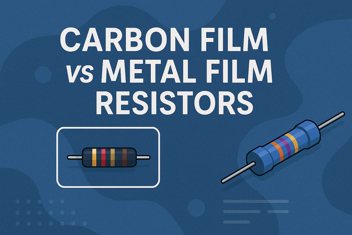 Carbon Film vs Metal Film Resistors: Complete Comparison Guide
19 May 20253282
 Semiconductor Devices: Impact on IoT and Modern Communication (Part- 2)
24 July 20242545
 Introduction to Wireless Charger
27 July 20214350
 Analog-to-Digital Converters (ADCs): Decrypting Resolutions and Sampling Rates
24 February 20224549
In Stock
United States
China
Canada
Japan
Russia
Germany
United Kingdom
Singapore
Italy
Hong Kong(China)
Taiwan(China)
France
Korea
Mexico
Netherlands
Malaysia
Austria
Spain
Switzerland
Poland
Thailand
Vietnam
India
United Arab Emirates
Afghanistan
Åland Islands
Albania
Algeria
American Samoa
Andorra
Angola
Anguilla
Antigua & Barbuda
Argentina
Armenia
Aruba
Australia
Azerbaijan
Bahamas
Bahrain
Bangladesh
Barbados
Belarus
Belgium
Belize
Benin
Bermuda
Bhutan
Bolivia
Bonaire, Sint Eustatius and Saba
Bosnia & Herzegovina
Botswana
Brazil
British Indian Ocean Territory
British Virgin Islands
Brunei
Bulgaria
Burkina Faso
Burundi
Cabo Verde
Cambodia
Cameroon
Cayman Islands
Central African Republic
Chad
Chile
Christmas Island
Cocos (Keeling) Islands
Colombia
Comoros
Congo
Congo (DRC)
Cook Islands
Costa Rica
Côte d’Ivoire
Croatia
Cuba
Curaçao
Cyprus
Czechia
Denmark
Djibouti
Dominica
Dominican Republic
Ecuador
Egypt
El Salvador
Equatorial Guinea
Eritrea
Estonia
Eswatini
Ethiopia
Falkland Islands
Faroe Islands
Fiji
Finland
French Guiana
French Polynesia
Gabon
Gambia
Georgia
Ghana
Gibraltar
Greece
Greenland
Grenada
Guadeloupe
Guam
Guatemala
Guernsey
Guinea
Guinea-Bissau
Guyana
Haiti
Honduras
Hungary
Iceland
Indonesia
Iran
Iraq
Ireland
Isle of Man
Israel
Jamaica
Jersey
Jordan
Kazakhstan
Kenya
Kiribati
Kosovo
Kuwait
Kyrgyzstan
Laos
Latvia
Lebanon
Lesotho
Liberia
Libya
Liechtenstein
Lithuania
Luxembourg
Macao(China)
Madagascar
Malawi
Maldives
Mali
Malta
Marshall Islands
Martinique
Mauritania
Mauritius
Mayotte
Micronesia
Moldova
Monaco
Mongolia
Montenegro
Montserrat
Morocco
Mozambique
Myanmar
Namibia
Nauru
Nepal
New Caledonia
New Zealand
Nicaragua
Niger
Nigeria
Niue
Norfolk Island
North Korea
North Macedonia
Northern Mariana Islands
Norway
Oman
Pakistan
Palau
Palestinian Authority
Panama
Papua New Guinea
Paraguay
Peru
Philippines
Pitcairn Islands
Portugal
Puerto Rico
Qatar
Réunion
Romania
Rwanda
Samoa
San Marino
São Tomé & Príncipe
Saudi Arabia
Senegal
Serbia
Seychelles
Sierra Leone
Sint Maarten
Slovakia
Slovenia
Solomon Islands
Somalia
South Africa
South Sudan
Sri Lanka
St Helena, Ascension, Tristan da Cunha
St. Barthélemy
St. Kitts & Nevis
St. Lucia
St. Martin
St. Pierre & Miquelon
St. Vincent & Grenadines
Sudan
Suriname
Svalbard & Jan Mayen
Sweden
Syria
Tajikistan
Tanzania
Timor-Leste
Togo
Tokelau
Tonga
Trinidad & Tobago
Tunisia
Turkey
Turkmenistan
Turks & Caicos Islands
Tuvalu
U.S. Outlying Islands
U.S. Virgin Islands
Uganda
Ukraine
Uruguay
Uzbekistan
Vanuatu
Vatican City
Venezuela
Wallis & Futuna
Yemen
Zambia
Zimbabwe