
How to Use STM32F427VIT6 for Complex Applications

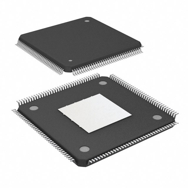
2MB 2M x 8 FLASH ARM® Cortex®-M4 32-Bit Microcontroller STM32F4 Series STM32F427 100 Pin 180MHz 3.3V 100-LQFP


2MB 2M x 8 FLASH ARM® Cortex®-M4 32-Bit Microcontroller STM32F4 Series STM32F427 100 Pin 180MHz 3.3V 100-LQFP
Learn how to integrate the STM32F427VIT6 microcontroller into your project with tips on hardware setup, software configuration, and leveraging advanced features.
Product Introduction
The STM32F427VIT6 stands out as a high-performance microcontroller designed for complex applications. Its 2 MB of Flash memory allows you to store large programs efficiently, while its 114 I/O pins provide extensive connectivity options. You can utilize its wide range of peripherals, including DMA, I²S, and Ethernet, to handle demanding tasks with ease. With support for advanced features like USB OTG and CANbus, this microcontroller offers unmatched scalability. Whether you're building industrial systems or consumer electronics, the STM32F427VIT6 delivers the power and versatility needed for success.
STM32F427VIT6 Hardware Integration
Pinout and Peripheral Overview
The STM32F427VIT6 microcontroller offers a versatile pinout that supports a wide range of peripherals. With 114 I/O pins, you can connect sensors, actuators, and communication modules to meet the needs of complex applications. The microcontroller includes advanced interfaces such as UART, SPI, I²C, and Ethernet, enabling seamless data exchange between devices.
You can also leverage its GPIO pins for general-purpose input/output tasks. These pins support multiple modes, including analog input, digital output, and alternate functions. For example, you can configure GPIO pins to control LEDs, read sensor data, or interface with external memory.
Tip: Use STM32CubeMX to visualize the pinout and configure peripherals efficiently. This tool simplifies the process of assigning functions to pins and ensures compatibility with your design.
Power Supply and Clock Configuration
The STM32F427VIT6 requires a reliable power supply to operate efficiently. It supports an operating voltage range of 1.8V to 3.6V, making it compatible with various power sources. You can use a linear voltage regulator or a switching regulator to provide stable power to the microcontroller.
The clock configuration is equally important for achieving optimal performance. The microcontroller operates at a maximum clock frequency of 180 MHz, allowing it to handle demanding tasks with ease. You can use an external crystal oscillator or the internal RC oscillator to generate the clock signal.
| Specification | Value |
|---|---|
| Operating Voltage Range | 1.8V to 3.6V |
| Maximum Clock Frequency | 180 MHz |
| Operating Temperature Range | -40°C to 85°C TA |
Note: Proper clock configuration ensures accurate timing for peripherals like UART and SPI. Use STM32CubeMX to set up the clock tree and verify the configuration.
External Components and Connections
To maximize the capabilities of the STM32F427VIT6, you need to integrate external components effectively. Common components include capacitors, resistors, and oscillators. Place decoupling capacitors near the power pins to reduce noise and improve stability.
For communication interfaces, connect pull-up or pull-down resistors to ensure proper signal levels. For example, use pull-up resistors on I²C lines to maintain high logic levels during idle states.
When connecting external memory, such as Flash or SRAM, ensure proper routing of address and data lines. The STM32F427VIT6 supports external memory interfaces, allowing you to expand storage for large applications.
Tip: Follow the microcontroller's datasheet and reference manual for detailed guidelines on external connections. Proper design minimizes signal interference and ensures reliable operation.
STM32F427VIT6 Software Setup
Setting Up the Development Environment
To start programming the STM32F427VIT6, you need a proper development environment. Begin by downloading and installing an Integrated Development Environment (IDE) like STM32CubeIDE or Keil uVision. These tools provide a user-friendly interface for writing, compiling, and debugging your code.
Next, install the necessary drivers for your ST-LINK programmer or debugger. This hardware allows you to upload your code to the microcontroller's flash memory. You can download the drivers from STMicroelectronics' official website.
After setting up the IDE and drivers, connect your STM32F427VIT6 to your computer using a USB cable and the ST-LINK device. Ensure the connections are secure to avoid communication errors.
Tip: Use a high-quality USB cable to prevent data transfer issues during programming.
Using STM32CubeMX for Code Generation
STM32CubeMX simplifies the process of configuring your microcontroller. Open the tool and create a new project. Select the STM32F427VIT6 from the list of available devices.
Once the project is created, you can configure the peripherals and pinout using the graphical interface. For example, you can enable UART for serial communication or SPI for interfacing with external devices. STM32CubeMX also allows you to set up the clock tree and power settings.
After completing the configuration, generate the initialization code. STM32CubeMX will create a project folder with all the necessary files. Import this folder into your IDE to start writing your application code.
Note: Always double-check the pin assignments and peripheral settings before generating the code.
Debugging Tools and Their Configuration
Debugging is an essential part of working with the STM32F427VIT6. Tools like ST-LINK and J-Link help you identify and fix issues in your code. Configure your debugger in the IDE by selecting the appropriate hardware and communication protocol.
Use breakpoints to pause the execution of your program and inspect variables. This feature helps you understand how your code interacts with the microcontroller's peripherals. You can also use the live watch feature to monitor real-time data changes.
Tip: Keep your debugging setup simple to avoid unnecessary complications. Focus on one issue at a time for efficient troubleshooting.
Programming the STM32F427VIT6
Writing and Uploading Code to Flash
To program the STM32F427VIT6, you need to write code and upload it to the microcontroller's flash memory. Flash serves as the non-volatile storage where your program resides, even when the device powers off. The process involves unlocking the flash, erasing existing data, writing new data, and locking the flash again to protect it.
Start by unlocking the flash memory using the HAL_FLASH_Unlock function. This step ensures that the flash will be unlocked and ready for programming. Once unlocked, erase the necessary sectors using the HAL_FLASHEx_Erase function. This function allows you to clear specific sections of the flash, making space for new data.
After erasing, use the HAL_FLASH_Program function to write data to flash. For example, you can write a program or configuration data to specific memory addresses. Always verify the written data by reading it back to ensure accuracy. Use the HAL_FLASH_Lock function to lock the flash after programming. This step ensures that the flash will be locked and protected from accidental modifications.
Here’s a simple example of writing data to flash:
HAL_FLASH_Unlock(); // Unlock flash memory
FLASH_EraseInitTypeDef EraseInitStruct;
EraseInitStruct.TypeErase = FLASH_TYPEERASE_SECTORS;
EraseInitStruct.Sector = FLASH_SECTOR_2;
EraseInitStruct.NbSectors = 1;
uint32_t SectorError;
HAL_FLASHEx_Erase(&EraseInitStruct, &SectorError); // Erase sector
HAL_FLASH_Program(FLASH_TYPEPROGRAM_WORD, 0x08008000, 0x12345678); // Write data
HAL_FLASH_Lock(); // Lock flash memory
Tip: Always test your flash programming code on a development board before deploying it to production hardware.
Configuring Peripherals (GPIO, UART, SPI)
The STM32F427VIT6 offers a wide range of peripherals, including GPIO, UART, and SPI. Configuring these peripherals allows you to interact with external devices and sensors effectively.
For GPIO, you can configure pins as input, output, or alternate functions. Use the HAL library to initialize GPIO pins. For example, to toggle an LED, configure the pin as an output and use the HAL_GPIO_WritePin function to control its state.
UART enables serial communication between the microcontroller and other devices. Configure the UART peripheral using the HAL library. Set the baud rate, data bits, and parity settings to match the connected device. Use the HAL_UART_Transmit and HAL_UART_Receive functions to send and receive data.
SPI is ideal for high-speed communication with devices like sensors and memory chips. Configure the SPI peripheral by setting the clock polarity, phase, and data size. Use the HAL_SPI_Transmit and HAL_SPI_Receive functions to exchange data.
Here’s an example of initializing and using UART:
UART_HandleTypeDef huart2;
huart2.Instance = USART2;
huart2.Init.BaudRate = 9600;
huart2.Init.WordLength = UART_WORDLENGTH_8B;
huart2.Init.StopBits = UART_STOPBITS_1;
huart2.Init.Parity = UART_PARITY_NONE;
huart2.Init.Mode = UART_MODE_TX_RX;
HAL_UART_Init(&huart2); // Initialize UART
HAL_UART_Transmit(&huart2, (uint8_t *)"Hello, UART!", 12, HAL_MAX_DELAY); // Transmit data
Note: Always refer to the STM32F427VIT6 reference manual for detailed peripheral configuration guidelines.
Leveraging Advanced Features (DMA, Timers, RTOS)
The STM32F427VIT6 includes advanced features like DMA, timers, and RTOS support, which enhance its capabilities for complex applications.
DMA (Direct Memory Access) allows peripherals to transfer data directly to and from memory without CPU intervention. This feature reduces CPU load and improves performance. For example, you can use DMA to transfer data from UART to memory. Configure the DMA controller using the HAL library and link it to the desired peripheral.
Timers are essential for generating precise time delays or PWM signals. The STM32F427VIT6 includes multiple timers that you can configure for various tasks. For instance, use a timer to generate a PWM signal for motor control or to measure input signal frequency.
RTOS (Real-Time Operating System) support enables multitasking in your application. You can use an RTOS like FreeRTOS to manage multiple tasks efficiently. For example, one task can handle sensor data while another manages communication. Use the STM32CubeIDE to integrate FreeRTOS into your project and create tasks using the xTaskCreate function.
Here’s an example of configuring a timer for PWM:
TIM_HandleTypeDef htim3;
htim3.Instance = TIM3;
htim3.Init.Prescaler = 84 - 1;
htim3.Init.CounterMode = TIM_COUNTERMODE_UP;
htim3.Init.Period = 1000 - 1;
htim3.Init.ClockDivision = TIM_CLOCKDIVISION_DIV1;
HAL_TIM_PWM_Init(&htim3); // Initialize timer for PWM
Tip: Use DMA and RTOS to optimize resource usage and improve the performance of your application.
Best Practices for Complex Applications
Optimizing Performance and Resource Usage
To optimize the performance of your stm32f427vit6-based application, focus on efficient resource management. Start by minimizing the use of unnecessary peripherals. Disable unused modules in your code to reduce power consumption and free up memory. For example, if your application does not require UART, disable it in the initialization phase.
Use the flash memory wisely. Store large datasets or configuration files in external memory to avoid overloading the internal flash. This approach ensures that your microcontroller operates smoothly, even in resource-intensive scenarios.
Leverage DMA for data transfers. This feature allows peripherals to communicate directly with memory, reducing CPU load. For instance, you can use DMA to transfer data from sensors to memory without interrupting other tasks.
Tip: Regularly profile your application to identify bottlenecks. Tools like STM32CubeIDE provide performance analysis features to help you optimize your code.
Debugging and Error Handling Strategies
Effective debugging is crucial for complex applications. Use breakpoints in your IDE to pause execution and inspect variables. This method helps you identify issues in real time. Additionally, enable error flags in your code to detect hardware faults. For example, check the status of the flash programming operation to ensure data integrity.
Implement robust error handling mechanisms. Use try-catch blocks or equivalent constructs to manage exceptions gracefully. For instance, if a sensor fails to respond, your code should retry the operation or switch to a backup sensor.
Note: Always log errors to a file or console. This practice helps you analyze issues after deployment.
Designing for Scalability and Future Expansion
Design your application with scalability in mind. Use modular code structures to simplify future updates. For example, separate the code for sensors, communication, and user interfaces into different modules. This approach makes it easier to add new features without affecting existing functionality.
Plan for memory expansion. The stm32f427vit6 supports external memory interfaces, allowing you to add more flash or SRAM as needed. This capability is particularly useful for applications that require large datasets or complex algorithms.
Tip: Document your code thoroughly. Clear documentation ensures that future developers can understand and expand your application efficiently.
Integrating the STM32F427VIT6 into your projects involves understanding its hardware, setting up the software environment, and leveraging its advanced features. By following the steps outlined in this guide, you can unlock its full potential for complex applications. Its high performance, extensive peripherals, and scalability make it an excellent choice for demanding tasks.
Pro Tip: Start small by experimenting with basic peripherals like GPIO or UART before diving into advanced features like DMA or RTOS.
🎯 Ready to get started? Grab an STM32F427VIT6 and begin building your next innovative project today!
FAQ
What makes the STM32F427VIT6 suitable for complex applications?
Its high-performance ARM Cortex-M4 core, 2 MB of Flash memory, and extensive peripherals make it ideal for demanding tasks. You can handle real-time operations, advanced communication protocols, and large datasets efficiently.
Can I use the STM32F427VIT6 with an RTOS?
Yes, it supports RTOS integration, such as FreeRTOS. You can manage multiple tasks simultaneously, improving efficiency in applications like robotics or the auav x2.1 flight controller.
How do I debug my STM32F427VIT6 project?
Use tools like ST-LINK or J-Link for debugging. Set breakpoints in your IDE to pause execution and inspect variables. This helps you identify and fix issues effectively.
What external components are essential for STM32F427VIT6?
You need decoupling capacitors for stable power, pull-up resistors for communication lines, and an external crystal oscillator for precise clock signals. These components ensure reliable operation.
Can I expand the memory of the STM32F427VIT6?
Yes, it supports external memory interfaces. You can connect additional Flash or SRAM to handle larger datasets or more complex algorithms.
Specifications
- TypeParameter
- Lifecycle Status
Lifecycle Status refers to the current stage of an electronic component in its product life cycle, indicating whether it is active, obsolete, or transitioning between these states. An active status means the component is in production and available for purchase. An obsolete status indicates that the component is no longer being manufactured or supported, and manufacturers typically provide a limited time frame for support. Understanding the lifecycle status is crucial for design engineers to ensure continuity and reliability in their projects.
ACTIVE (Last Updated: 7 months ago) - Factory Lead Time12 Weeks
- Mounting Type
The "Mounting Type" in electronic components refers to the method used to attach or connect a component to a circuit board or other substrate, such as through-hole, surface-mount, or panel mount.
Surface Mount - Package / Case
refers to the protective housing that encases an electronic component, providing mechanical support, electrical connections, and thermal management.
100-LQFP - Surface Mount
having leads that are designed to be soldered on the side of a circuit board that the body of the component is mounted on.
YES - Number of Pins100
- Data ConvertersA/D 16x12b; D/A 2x12b
- Number of I/Os82
- Watchdog TimersYes
- Operating Temperature
The operating temperature is the range of ambient temperature within which a power supply, or any other electrical equipment, operate in. This ranges from a minimum operating temperature, to a peak or maximum operating temperature, outside which, the power supply may fail.
-40°C~85°C TA - Packaging
Semiconductor package is a carrier / shell used to contain and cover one or more semiconductor components or integrated circuits. The material of the shell can be metal, plastic, glass or ceramic.
Tray - Series
In electronic components, the "Series" refers to a group of products that share similar characteristics, designs, or functionalities, often produced by the same manufacturer. These components within a series typically have common specifications but may vary in terms of voltage, power, or packaging to meet different application needs. The series name helps identify and differentiate between various product lines within a manufacturer's catalog.
STM32F4 - JESD-609 Code
The "JESD-609 Code" in electronic components refers to a standardized marking code that indicates the lead-free solder composition and finish of electronic components for compliance with environmental regulations.
e4 - Part Status
Parts can have many statuses as they progress through the configuration, analysis, review, and approval stages.
Active - Moisture Sensitivity Level (MSL)
Moisture Sensitivity Level (MSL) is a standardized rating that indicates the susceptibility of electronic components, particularly semiconductors, to moisture-induced damage during storage and the soldering process, defining the allowable exposure time to ambient conditions before they require special handling or baking to prevent failures
3 (168 Hours) - Number of Terminations100
- Terminal Finish
Terminal Finish refers to the surface treatment applied to the terminals or leads of electronic components to enhance their performance and longevity. It can improve solderability, corrosion resistance, and overall reliability of the connection in electronic assemblies. Common finishes include nickel, gold, and tin, each possessing distinct properties suitable for various applications. The choice of terminal finish can significantly impact the durability and effectiveness of electronic devices.
Nickel/Palladium/Gold (Ni/Pd/Au) - Terminal Position
In electronic components, the term "Terminal Position" refers to the physical location of the connection points on the component where external electrical connections can be made. These connection points, known as terminals, are typically used to attach wires, leads, or other components to the main body of the electronic component. The terminal position is important for ensuring proper connectivity and functionality of the component within a circuit. It is often specified in technical datasheets or component specifications to help designers and engineers understand how to properly integrate the component into their circuit designs.
QUAD - Terminal Form
Occurring at or forming the end of a series, succession, or the like; closing; concluding.
GULL WING - Peak Reflow Temperature (Cel)
Peak Reflow Temperature (Cel) is a parameter that specifies the maximum temperature at which an electronic component can be exposed during the reflow soldering process. Reflow soldering is a common method used to attach electronic components to a circuit board. The Peak Reflow Temperature is crucial because it ensures that the component is not damaged or degraded during the soldering process. Exceeding the specified Peak Reflow Temperature can lead to issues such as component failure, reduced performance, or even permanent damage to the component. It is important for manufacturers and assemblers to adhere to the recommended Peak Reflow Temperature to ensure the reliability and functionality of the electronic components.
260 - Supply Voltage
Supply voltage refers to the electrical potential difference provided to an electronic component or circuit. It is crucial for the proper operation of devices, as it powers their functions and determines performance characteristics. The supply voltage must be within specified limits to ensure reliability and prevent damage to components. Different electronic devices have specific supply voltage requirements, which can vary widely depending on their design and intended application.
3.3V - Terminal Pitch
The center distance from one pole to the next.
0.5mm - Frequency
In electronic components, the parameter "Frequency" refers to the rate at which a signal oscillates or cycles within a given period of time. It is typically measured in Hertz (Hz) and represents how many times a signal completes a full cycle in one second. Frequency is a crucial aspect in electronic components as it determines the behavior and performance of various devices such as oscillators, filters, and communication systems. Understanding the frequency characteristics of components is essential for designing and analyzing electronic circuits to ensure proper functionality and compatibility with other components in a system.
180MHz - Base Part Number
The "Base Part Number" (BPN) in electronic components serves a similar purpose to the "Base Product Number." It refers to the primary identifier for a component that captures the essential characteristics shared by a group of similar components. The BPN provides a fundamental way to reference a family or series of components without specifying all the variations and specific details.
STM32F427 - Supply Voltage-Max (Vsup)
The parameter "Supply Voltage-Max (Vsup)" in electronic components refers to the maximum voltage that can be safely applied to the component without causing damage. It is an important specification to consider when designing or using electronic circuits to ensure the component operates within its safe operating limits. Exceeding the maximum supply voltage can lead to overheating, component failure, or even permanent damage. It is crucial to adhere to the specified maximum supply voltage to ensure the reliable and safe operation of the electronic component.
3.6V - Power Supplies
an electronic circuit that converts the voltage of an alternating current (AC) into a direct current (DC) voltage.?
2/3.3V - Interface
In electronic components, the term "Interface" refers to the point at which two different systems, devices, or components connect and interact with each other. It can involve physical connections such as ports, connectors, or cables, as well as communication protocols and standards that facilitate the exchange of data or signals between the connected entities. The interface serves as a bridge that enables seamless communication and interoperability between different parts of a system or between different systems altogether. Designing a reliable and efficient interface is crucial in ensuring proper functionality and performance of electronic components and systems.
CAN, EBI/EMI, Ethernet, I2C, I2S, IrDA, LIN, SPI, UART, USART, USB - Memory Size
The memory capacity is the amount of data a device can store at any given time in its memory.
2MB - Oscillator Type
Wien Bridge Oscillator; RC Phase Shift Oscillator; Hartley Oscillator; Voltage Controlled Oscillator; Colpitts Oscillator; Clapp Oscillators; Crystal Oscillators; Armstrong Oscillator.
Internal - RAM Size
RAM size refers to the amount of random access memory (RAM) available in an electronic component, such as a computer or smartphone. RAM is a type of volatile memory that stores data and instructions that are actively being used by the device's processor. The RAM size is typically measured in gigabytes (GB) and determines how much data the device can store and access quickly for processing. A larger RAM size allows for smoother multitasking, faster loading times, and better overall performance of the electronic component. It is an important factor to consider when choosing a device, especially for tasks that require a lot of memory, such as gaming, video editing, or running multiple applications simultaneously.
256K x 8 - Voltage - Supply (Vcc/Vdd)
Voltage - Supply (Vcc/Vdd) is a key parameter in electronic components that specifies the voltage level required for the proper operation of the device. It represents the power supply voltage that needs to be provided to the component for it to function correctly. This parameter is crucial as supplying the component with the correct voltage ensures that it operates within its specified limits and performance characteristics. It is typically expressed in volts (V) and is an essential consideration when designing and using electronic circuits to prevent damage and ensure reliable operation.
1.8V~3.6V - uPs/uCs/Peripheral ICs Type
The parameter "uPs/uCs/Peripheral ICs Type" refers to the classification of various integrated circuits used in electronic devices. It encompasses microprocessors (uPs), microcontrollers (uCs), and peripheral integrated circuits that provide additional functionalities. This classification helps in identifying the specific type of chip used for processing tasks, controlling hardware, or interfacing with other components in a system. Understanding this parameter is essential for selecting the appropriate electronic components for a given application.
MICROCONTROLLER, RISC - Core Processor
The term "Core Processor" typically refers to the central processing unit (CPU) of a computer or electronic device. It is the primary component responsible for executing instructions, performing calculations, and managing data within the system. The core processor is often considered the brain of the device, as it controls the overall operation and functionality. It is crucial for determining the speed and performance capabilities of the device, as well as its ability to handle various tasks and applications efficiently. In modern devices, core processors can have multiple cores, allowing for parallel processing and improved multitasking capabilities.
ARM® Cortex®-M4 - Peripherals
In the context of electronic components, "Peripherals" refer to devices or components that are connected to a main system or device to enhance its functionality or provide additional features. These peripherals can include input devices such as keyboards, mice, and touchscreens, as well as output devices like monitors, printers, and speakers. Other examples of peripherals include external storage devices, network adapters, and cameras. Essentially, peripherals are external devices that expand the capabilities of a main electronic system or device.
Brown-out Detect/Reset, DMA, I2S, POR, PWM, WDT - Program Memory Type
Program memory typically refers to flash memory when it is used to hold the program (instructions). Program memory may also refer to a hard drive or solid state drive (SSD). Contrast with data memory.
FLASH - Core Size
Core size in electronic components refers to the physical dimensions of the core material used in devices such as inductors and transformers. The core size directly impacts the performance characteristics of the component, including its inductance, saturation current, and frequency response. A larger core size typically allows for higher power handling capabilities and lower core losses, while a smaller core size may result in a more compact design but with limitations on power handling and efficiency. Designers must carefully select the core size based on the specific requirements of the application to achieve optimal performance and efficiency.
32-Bit - Program Memory Size
Program Memory Size refers to the amount of memory available in an electronic component, such as a microcontroller or microprocessor, that is used to store program instructions. This memory is non-volatile, meaning that the data stored in it is retained even when the power is turned off. The program memory size determines the maximum amount of code that can be stored and executed by the electronic component. It is an important parameter to consider when selecting a component for a specific application, as insufficient program memory size may limit the functionality or performance of the device.
2MB 2M x 8 - Connectivity
In electronic components, "Connectivity" refers to the ability of a component to establish and maintain connections with other components or devices within a circuit. It is a crucial parameter that determines how easily signals can be transmitted between different parts of a circuit. Connectivity can be influenced by factors such as the number of input and output ports, the type of connectors used, and the overall design of the component. Components with good connectivity are essential for ensuring reliable and efficient operation of electronic systems.
CANbus, EBI/EMI, Ethernet, I2C, IrDA, LINbus, SPI, UART/USART, USB OTG - Bit Size
In electronic components, "Bit Size" refers to the number of bits that can be processed or stored by a particular component. A bit is the smallest unit of data in computing and can have a value of either 0 or 1. The Bit Size parameter is commonly used to describe the capacity or performance of components such as microprocessors, memory modules, and data buses. A larger Bit Size generally indicates a higher processing capability or storage capacity, allowing for more complex operations and larger amounts of data to be handled efficiently. It is an important specification to consider when selecting electronic components for specific applications that require certain levels of performance and data processing capabilities.
32 - Has ADC
Has ADC refers to the presence of an Analog-to-Digital Converter (ADC) in an electronic component. An ADC is a crucial component in many electronic devices as it converts analog signals, such as voltage or current, into digital data that can be processed by a digital system. Having an ADC allows the electronic component to interface with analog signals and convert them into a format that can be manipulated and analyzed digitally. This parameter is important for applications where analog signals need to be converted into digital form for further processing or control.
YES - DMA Channels
DMA (Direct Memory Access) Channels are a feature found in electronic components such as microcontrollers, microprocessors, and peripheral devices. DMA Channels allow data to be transferred directly between peripherals and memory without involving the CPU, thereby reducing the burden on the CPU and improving overall system performance. Each DMA Channel is typically assigned to a specific peripheral device or memory region, enabling efficient data transfer operations. The number of DMA Channels available in a system determines the concurrent data transfer capabilities and can vary depending on the specific hardware design. Overall, DMA Channels play a crucial role in optimizing data transfer efficiency and system performance in electronic devices.
YES - Data Rate
Data Rate is defined as the amount of data transmitted during a specified time period over a network. It is the speed at which data is transferred from one device to another or between a peripheral device and the computer. It is generally measured in Mega bits per second(Mbps) or Mega bytes per second(MBps).
480 Mbps - Data Bus Width
The data bus width in electronic components refers to the number of bits that can be transferred simultaneously between the processor and memory. It determines the amount of data that can be processed and transferred in a single operation. A wider data bus allows for faster data transfer speeds and improved overall performance of the electronic device. Common data bus widths include 8-bit, 16-bit, 32-bit, and 64-bit, with higher numbers indicating a larger capacity for data transfer. The data bus width is an important specification to consider when evaluating the speed and efficiency of a computer system or other electronic device.
32b - PWM Channels
PWM Channels, or Pulse Width Modulation Channels, refer to the number of independent PWM outputs available in an electronic component, such as a microcontroller or a motor driver. PWM is a technique used to generate analog-like signals by varying the duty cycle of a square wave signal. Each PWM channel can control the output of a specific device or component by adjusting the pulse width of the signal. Having multiple PWM channels allows for precise control of multiple devices simultaneously, making it a valuable feature in applications such as motor control, LED dimming, and audio signal generation. The number of PWM channels available in a component determines the flexibility and complexity of the system it can control.
YES - Number of Timers/Counters14
- Core Architecture
In electronic components, the term "Core Architecture" refers to the fundamental design and structure of the component's internal circuitry. It encompasses the arrangement of key components, such as processors, memory units, and input/output interfaces, within the device. The core architecture plays a crucial role in determining the component's performance, power efficiency, and overall capabilities. Different core architectures are optimized for specific applications and requirements, such as high-speed processing, low power consumption, or specialized functions. Understanding the core architecture of electronic components is essential for engineers and designers to select the most suitable components for their projects.
ARM - CPU Family
CPU Family refers to a classification of microprocessors that share a common architecture and design traits. It signifies a group of processors that are typically produced by the same manufacturer and have similar functionality and features. The CPU Family can encompass various models that may differ in performance, power consumption, and specific capabilities but retain a unified core design, allowing for compatibility with software and hardware. This classification helps users and developers to understand the performance characteristics and upgrade pathways of different CPU models within the same family.
CORTEX-M4 - Number of ADC Channels16
- Number of USB Channels1
- Height1.45mm
- Length14mm
- Width14.2mm
- REACH SVHC
The parameter "REACH SVHC" in electronic components refers to the compliance with the Registration, Evaluation, Authorization, and Restriction of Chemicals (REACH) regulation regarding Substances of Very High Concern (SVHC). SVHCs are substances that may have serious effects on human health or the environment, and their use is regulated under REACH to ensure their safe handling and minimize their impact.Manufacturers of electronic components need to declare if their products contain any SVHCs above a certain threshold concentration and provide information on the safe use of these substances. This information allows customers to make informed decisions about the potential risks associated with using the components and take appropriate measures to mitigate any hazards.Ensuring compliance with REACH SVHC requirements is essential for electronics manufacturers to meet regulatory standards, protect human health and the environment, and maintain transparency in their supply chain. It also demonstrates a commitment to sustainability and responsible manufacturing practices in the electronics industry.
No SVHC - Radiation Hardening
Radiation hardening is the process of making electronic components and circuits resistant to damage or malfunction caused by high levels of ionizing radiation, especially for environments in outer space (especially beyond the low Earth orbit), around nuclear reactors and particle accelerators, or during nuclear accidents or nuclear warfare.
No - RoHS Status
RoHS means “Restriction of Certain Hazardous Substances” in the “Hazardous Substances Directive” in electrical and electronic equipment.
ROHS3 Compliant - Lead Free
Lead Free is a term used to describe electronic components that do not contain lead as part of their composition. Lead is a toxic material that can have harmful effects on human health and the environment, so the electronics industry has been moving towards lead-free components to reduce these risks. Lead-free components are typically made using alternative materials such as silver, copper, and tin. Manufacturers must comply with regulations such as the Restriction of Hazardous Substances (RoHS) directive to ensure that their products are lead-free and environmentally friendly.
Lead Free
Parts with Similar Specs
- ImagePart NumberManufacturerPackage / CaseNumber of PinsCore ArchitectureData Bus WidthNumber of I/OInterfaceMemory SizeSupply VoltageView Compare
![STM32F427VIT6]()
STM32F427VIT6
100-LQFP
100
ARM
32 b
82
CAN, EBI/EMI, Ethernet, I2C, I2S, IrDA, LIN, SPI, UART, USART, USB
2 MB
3.3 V
![STM32F429VIT6]()
100-LQFP
100
ARM
32 b
82
CAN, EBI/EMI, Ethernet, I2C, IrDA, LIN, SPI, UART, USART, USB
2 MB
3.3 V
![XMC4700F100K2048AAXQMA1]()
100-LQFP
100
ARM
32 b
82
CAN, EBI/EMI, Ethernet, I2C, I2S, IrDA, LIN, SDIO, SPI, UART, USART, USB
2 MB
3.3 V
![STM32F437VIT6]()
100-LQFP
100
ARM
32 b
82
CAN, EBI/EMI, Ethernet, I2C, I2S, IrDA, LIN, SPI, UART, USART, USB
2 MB
3.3 V
![STM32F437VIT6TR]()
100-LQFP Exposed Pad
100
ARM
32 b
75
CAN, EBI/EMI, Ethernet, I2C, I2S, LIN, MMC, SD, SPI, UART, USART, USB
2 MB
1.3 V


Datasheet PDF
- Datasheets :
 BSH201 MOS Transistor: SOT-23, 60V, 0.3 A, Datasheet PDF
28 February 20221868
![LMR®-400 VS RG213[Video]: Pros and Cons of LMR400 VS RG213](https://res.utmel.com/Images/Article/d2dd0c09-f9bd-4cec-b315-54f693c0095f.jpg) LMR®-400 VS RG213[Video]: Pros and Cons of LMR400 VS RG213
LMR®-400 VS RG213[Video]: Pros and Cons of LMR400 VS RG21312 June 202414019
 Comprehensive Guide to STM32L431CBT6 for Developers
24 July 2025207
 EP4CE6E22C8N Intel/Altera: Specifications, Features and Applications
25 March 2025451
 Exploring the STM32L083xx Ultra-Low-Power 32-bit MCU
29 February 2024137
- STM32F030C6T6 vs STM32F072C8T6 STMicroelectronics Microcontrollers
11 June 2025157
 PMBT2222A Transistor: PMBT2222A, SOT23, Datasheet
28 April 20222045
![HT7333 How to use a HT7333 IC?[Video]](https://res.utmel.com/Images/Article/882d6c87-9c81-4515-b682-29cdfa70cf1a.png) HT7333 How to use a HT7333 IC?[Video]
HT7333 How to use a HT7333 IC?[Video]18 April 20223531
 Introduction to DC Amplifier
07 November 202514601
 Working Principles and Applications of Pressure Sensors
07 April 202533966
 Hybrid Sources Powered Electric Vehicles - Part 2
20 March 20232621
 Buffer Amplifier | Operating Principle, Advantages, and Applications
21 July 20257439
 Latest MLPerf Results: NVIDIA H100 GPUs Ride to the Top
13 September 20222319
 An Overview of 12 Important CPU Specs
18 December 202111408
 Detecting Wafer Patterns using Semi-Supervised Learning
21 October 20221148
 Analysis of SiP (System in Package)
12 January 20225876
STMicroelectronics
In Stock: 7506
United States
China
Canada
Japan
Russia
Germany
United Kingdom
Singapore
Italy
Hong Kong(China)
Taiwan(China)
France
Korea
Mexico
Netherlands
Malaysia
Austria
Spain
Switzerland
Poland
Thailand
Vietnam
India
United Arab Emirates
Afghanistan
Åland Islands
Albania
Algeria
American Samoa
Andorra
Angola
Anguilla
Antigua & Barbuda
Argentina
Armenia
Aruba
Australia
Azerbaijan
Bahamas
Bahrain
Bangladesh
Barbados
Belarus
Belgium
Belize
Benin
Bermuda
Bhutan
Bolivia
Bonaire, Sint Eustatius and Saba
Bosnia & Herzegovina
Botswana
Brazil
British Indian Ocean Territory
British Virgin Islands
Brunei
Bulgaria
Burkina Faso
Burundi
Cabo Verde
Cambodia
Cameroon
Cayman Islands
Central African Republic
Chad
Chile
Christmas Island
Cocos (Keeling) Islands
Colombia
Comoros
Congo
Congo (DRC)
Cook Islands
Costa Rica
Côte d’Ivoire
Croatia
Cuba
Curaçao
Cyprus
Czechia
Denmark
Djibouti
Dominica
Dominican Republic
Ecuador
Egypt
El Salvador
Equatorial Guinea
Eritrea
Estonia
Eswatini
Ethiopia
Falkland Islands
Faroe Islands
Fiji
Finland
French Guiana
French Polynesia
Gabon
Gambia
Georgia
Ghana
Gibraltar
Greece
Greenland
Grenada
Guadeloupe
Guam
Guatemala
Guernsey
Guinea
Guinea-Bissau
Guyana
Haiti
Honduras
Hungary
Iceland
Indonesia
Iran
Iraq
Ireland
Isle of Man
Israel
Jamaica
Jersey
Jordan
Kazakhstan
Kenya
Kiribati
Kosovo
Kuwait
Kyrgyzstan
Laos
Latvia
Lebanon
Lesotho
Liberia
Libya
Liechtenstein
Lithuania
Luxembourg
Macao(China)
Madagascar
Malawi
Maldives
Mali
Malta
Marshall Islands
Martinique
Mauritania
Mauritius
Mayotte
Micronesia
Moldova
Monaco
Mongolia
Montenegro
Montserrat
Morocco
Mozambique
Myanmar
Namibia
Nauru
Nepal
New Caledonia
New Zealand
Nicaragua
Niger
Nigeria
Niue
Norfolk Island
North Korea
North Macedonia
Northern Mariana Islands
Norway
Oman
Pakistan
Palau
Palestinian Authority
Panama
Papua New Guinea
Paraguay
Peru
Philippines
Pitcairn Islands
Portugal
Puerto Rico
Qatar
Réunion
Romania
Rwanda
Samoa
San Marino
São Tomé & Príncipe
Saudi Arabia
Senegal
Serbia
Seychelles
Sierra Leone
Sint Maarten
Slovakia
Slovenia
Solomon Islands
Somalia
South Africa
South Sudan
Sri Lanka
St Helena, Ascension, Tristan da Cunha
St. Barthélemy
St. Kitts & Nevis
St. Lucia
St. Martin
St. Pierre & Miquelon
St. Vincent & Grenadines
Sudan
Suriname
Svalbard & Jan Mayen
Sweden
Syria
Tajikistan
Tanzania
Timor-Leste
Togo
Tokelau
Tonga
Trinidad & Tobago
Tunisia
Turkey
Turkmenistan
Turks & Caicos Islands
Tuvalu
U.S. Outlying Islands
U.S. Virgin Islands
Uganda
Ukraine
Uruguay
Uzbekistan
Vanuatu
Vatican City
Venezuela
Wallis & Futuna
Yemen
Zambia
Zimbabwe
![STM32F103RBT6]() STM32F103RBT6
STM32F103RBT6STMicroelectronics
![STM32F103ZET6]() STM32F103ZET6
STM32F103ZET6STMicroelectronics
![STM32H743IIT6]() STM32H743IIT6
STM32H743IIT6STMicroelectronics
![STM32F407VET6]() STM32F407VET6
STM32F407VET6STMicroelectronics
![STM32F405RGT6]() STM32F405RGT6
STM32F405RGT6STMicroelectronics
![STM32F030C8T6]() STM32F030C8T6
STM32F030C8T6STMicroelectronics
![STM32F100C8T6B]() STM32F100C8T6B
STM32F100C8T6BSTMicroelectronics
![STM32F103VBT6]() STM32F103VBT6
STM32F103VBT6STMicroelectronics
![STM8S003F3U6TR]() STM8S003F3U6TR
STM8S003F3U6TRSTMicroelectronics
![STM32F429ZIT6]() STM32F429ZIT6
STM32F429ZIT6STMicroelectronics


