
LTST-C191KRKT SMD LED: Circuit, Pinout, and Datasheet


LED RED CLEAR SMD
The LTST-C191KRKT is a Red 1.6 x 0.8 x 1.1 mm 130° Water Clear 54 mcd 2 V SMT LED Chip. This article mainly introduces circuit, pinout, datasheet and other detailed information about Lite-On Inc. LTST-C191KRKT.

Desoldering SMD LED
- LTST-C191KRKT Description
- LTST-C191KRKT Schematic
- LTST-C191KRKT CAD Model
- LTST-C191KRKT Features
- Specifications
- Parts with Similar Specs
- Make ESP32 Breakout Board with LTST-C191KRKT
- LTST-C191KRKT Drive Method
- LTST-C191KRKT Alternatives
- LTST-C191KRKT Applications
- LTST-C191KRKT Package
- LTST-C191KRKT Storage
- LTST-C191KRKT ESD (Electrostatic Discharge)
- LTST-C191KRKT Manufacturer
- Trend Analysis
- Datasheet PDF
LTST-C191KRKT Description
The LTST-C191KRKT is a Red 1.6 x 0.8 x 1.1 mm 130° Water Clear 54 mcd 2 V SMD LED Chip. For automated PC board assembly and space-sensitive applications, Lite-On offers SMD LED bulbs in microscopic sizes and unique configurations. These SMD LED lamps can be used in a wide range of electronic products.
LTST-C191KRKT Schematic

LTST-C191KRKT CAD Model


LTST-C191KRKT Features
* Meet ROHS, Green Product.
* Super Thin (0.55H mm) Chip LED.
* Ultra Bright AlInGaP Chip LED.
* Package In 8mm Tape On 13" Diameter Reels.
* EIA STD Package.
* I.C. Compatible.
* Compatible With Automatic Placement Equipment.
* Compatible With Infrared Reflow Solder Process.
Specifications
- TypeParameter
- Factory Lead Time12 Weeks
- Mount
In electronic components, the term "Mount" typically refers to the method or process of physically attaching or fixing a component onto a circuit board or other electronic device. This can involve soldering, adhesive bonding, or other techniques to secure the component in place. The mounting process is crucial for ensuring proper electrical connections and mechanical stability within the electronic system. Different components may have specific mounting requirements based on their size, shape, and function, and manufacturers provide guidelines for proper mounting procedures to ensure optimal performance and reliability of the electronic device.
Surface Mount - Mounting Type
The "Mounting Type" in electronic components refers to the method used to attach or connect a component to a circuit board or other substrate, such as through-hole, surface-mount, or panel mount.
Surface Mount - Package / Case
refers to the protective housing that encases an electronic component, providing mechanical support, electrical connections, and thermal management.
0603 (1608 Metric) - Number of Pins2
- Shape
In electronic components, the parameter "Shape" refers to the physical form or outline of the component. It describes the external appearance of the component, including its dimensions, size, and overall structure. The shape of an electronic component can vary widely depending on its function and design requirements. Common shapes include rectangular, cylindrical, square, and circular, among others. The shape of a component is an important consideration in the design and layout of electronic circuits, as it can impact factors such as space utilization, heat dissipation, and ease of assembly.
RECTANGULAR - Number of Elements1
- Wavelength-dominant631nm
- Packaging
Semiconductor package is a carrier / shell used to contain and cover one or more semiconductor components or integrated circuits. The material of the shell can be metal, plastic, glass or ceramic.
Cut Tape (CT) - Published2007
- Size / Dimension
In electronic components, the parameter "Size / Dimension" refers to the physical dimensions of the component, such as its length, width, and height. These dimensions are crucial for determining how the component will fit into a circuit or system, as well as for ensuring compatibility with other components and the overall design requirements. The size of a component can also impact its performance characteristics, thermal properties, and overall functionality within a given application. Engineers and designers must carefully consider the size and dimensions of electronic components to ensure proper integration and functionality within their designs.
1.60mm Lx0.80mm W - JESD-609 Code
The "JESD-609 Code" in electronic components refers to a standardized marking code that indicates the lead-free solder composition and finish of electronic components for compliance with environmental regulations.
e3 - Pbfree Code
The "Pbfree Code" parameter in electronic components refers to the code or marking used to indicate that the component is lead-free. Lead (Pb) is a toxic substance that has been widely used in electronic components for many years, but due to environmental concerns, there has been a shift towards lead-free alternatives. The Pbfree Code helps manufacturers and users easily identify components that do not contain lead, ensuring compliance with regulations and promoting environmentally friendly practices. It is important to pay attention to the Pbfree Code when selecting electronic components to ensure they meet the necessary requirements for lead-free applications.
yes - Part Status
Parts can have many statuses as they progress through the configuration, analysis, review, and approval stages.
Active - Moisture Sensitivity Level (MSL)
Moisture Sensitivity Level (MSL) is a standardized rating that indicates the susceptibility of electronic components, particularly semiconductors, to moisture-induced damage during storage and the soldering process, defining the allowable exposure time to ambient conditions before they require special handling or baking to prevent failures
2A (4 Weeks) - Number of Terminations2
- Terminal Finish
Terminal Finish refers to the surface treatment applied to the terminals or leads of electronic components to enhance their performance and longevity. It can improve solderability, corrosion resistance, and overall reliability of the connection in electronic assemblies. Common finishes include nickel, gold, and tin, each possessing distinct properties suitable for various applications. The choice of terminal finish can significantly impact the durability and effectiveness of electronic devices.
Tin (Sn) - Max Operating Temperature
The Maximum Operating Temperature is the maximum body temperature at which the thermistor is designed to operate for extended periods of time with acceptable stability of its electrical characteristics.
85°C - Min Operating Temperature
The "Min Operating Temperature" parameter in electronic components refers to the lowest temperature at which the component is designed to operate effectively and reliably. This parameter is crucial for ensuring the proper functioning and longevity of the component, as operating below this temperature may lead to performance issues or even damage. Manufacturers specify the minimum operating temperature to provide guidance to users on the environmental conditions in which the component can safely operate. It is important to adhere to this parameter to prevent malfunctions and ensure the overall reliability of the electronic system.
-55°C - ColorRed
- Additional Feature
Any Feature, including a modified Existing Feature, that is not an Existing Feature.
IC COMPATIBLE - Power Rating
The "Power Rating" of an electronic component refers to the maximum amount of power that the component can handle or dissipate without being damaged. It is typically measured in watts and is an important specification to consider when designing or selecting components for a circuit. Exceeding the power rating of a component can lead to overheating, malfunction, or even permanent damage. It is crucial to ensure that the power rating of each component in a circuit is sufficient to handle the power levels expected during normal operation to maintain the reliability and longevity of the electronic system.
75mW - Packing Method
The packing method in electronic components refers to the technique used to package and protect the component during shipping and handling. It encompasses various forms including tape and reel, tray, tube, or bulk packaging, each suited for different types of components and manufacturing processes. The choice of packing method can affect the ease of handling, storage, and the efficiency of assembly in automated processes. Additionally, it plays a crucial role in ensuring the reliability and integrity of the components until they are used in electronic devices.
TAPE AND REEL 7" - Number of Functions1
- Depth
In electronic components, "Depth" typically refers to the measurement of the distance from the front to the back of the component. It is an important parameter to consider when designing or selecting components for a project, as it determines how much space the component will occupy within a circuit or device. The depth of a component can impact the overall size and layout of the circuit board or enclosure in which it will be installed. It is usually specified in millimeters or inches and is crucial for ensuring proper fit and functionality within the intended application.
800μm - Case Code (Metric)
Case Code (Metric) in electronic components refers to a standardized system that specifies the dimensions of surface-mount devices (SMD) in millimeters, consisting of a four-digit number where the first two digits represent the width and the last two digits represent the height of the component, measured in tenths of a millimeter. The metric case codes are standardized by organizations such as the EIA and IEC, and are often compared to the Imperial code which uses inches, allowing for easier identification and selection of components across different regions and industries. This coding system is widely used in the design and manufacturing of electronic devices, particularly in applications requiring compact and efficient component layouts, and is essential for engineers and designers to ensure proper component selection and facilitate the assembly process in electronic manufacturing.
1608 - Case Code (Imperial)
The term "Case Code (Imperial)" in electronic components refers to a standardized system used to specify the physical dimensions and package types of components, particularly capacitors and resistors. This code helps manufacturers and engineers identify the size and form factor of the component, ensuring compatibility with circuit designs and PCB layouts. In the context of electronic components, the Case Code (Imperial) typically follows a numerical format that indicates the length and width of the component in inches. For example, a Case Code of 1206 signifies a component that measures 0.12 inches by 0.06 inches. This coding system is essential for selecting the correct components for specific applications, as it provides a quick reference to the physical characteristics of the part, including its footprint and mounting style.
0603 - Configuration
The parameter "Configuration" in electronic components refers to the specific arrangement or setup of the components within a circuit or system. It encompasses how individual elements are interconnected and their physical layout. Configuration can affect the functionality, performance, and efficiency of the electronic system, and may influence factors such as signal flow, impedance, and power distribution. Understanding the configuration is essential for design, troubleshooting, and optimizing electronic devices.
Standard - Voltage
Voltage is a measure of the electric potential difference between two points in an electrical circuit. It is typically represented by the symbol "V" and is measured in volts. Voltage is a crucial parameter in electronic components as it determines the flow of electric current through a circuit. It is responsible for driving the movement of electrons from one point to another, providing the energy needed for electronic devices to function properly. In summary, voltage is a fundamental concept in electronics that plays a key role in the operation and performance of electronic components.
2V - Current
In electronic components, "Current" refers to the flow of electric charge through a conductor or semiconductor material. It is measured in amperes (A) and represents the rate at which electric charge is moving past a specific point in a circuit. Current is a crucial parameter in electronics as it determines the amount of power being consumed or delivered by a component. Understanding and controlling current is essential for designing and operating electronic circuits efficiently and safely. In summary, current is a fundamental electrical quantity that plays a key role in the functionality and performance of electronic components.
2A - Power Dissipation
the process by which an electronic or electrical device produces heat (energy loss or waste) as an undesirable derivative of its primary action.
75mW - Viewing Angle
the angle at which a display can be viewed with acceptable visual performance.
130° - Optoelectronic Device Type
Optoelectronic Device Type refers to the classification of electronic components that can both detect and emit light. These devices convert electrical signals into light or vice versa, making them essential for applications such as optical communication, sensing, and display technologies. Common types of optoelectronic devices include light-emitting diodes (LEDs), photodiodes, phototransistors, and laser diodes. Understanding the optoelectronic device type is crucial for selecting the appropriate component for a specific application based on factors such as wavelength, power output, and sensitivity.
SINGLE COLOR LED - Forward Current
Current which flows upon application of forward voltage.
30mA - Current - Test
Current - Test is a parameter in electronic components that refers to the maximum current that the component can handle during testing without being damaged. This parameter is crucial for determining the operational limits of the component and ensuring its reliability under specified conditions. It is typically specified in the component's datasheet and is important for designers and engineers to consider when designing circuits to prevent overloading the component. Testing the component at or below the specified "Current - Test" value helps ensure its proper functioning and longevity in the intended application.
20mA - Lens Style
In the context of electronic components, the parameter "Lens Style" typically refers to the design or shape of the lens used in optical components such as LEDs, photodiodes, or sensors. The lens style can affect the light output, beam angle, and overall performance of the component. Common lens styles include flat top, dome, narrow beam, wide beam, and diffused lenses. Choosing the appropriate lens style is important for achieving the desired light distribution and optical characteristics in electronic devices. Manufacturers often provide specifications on the lens style to help users select the most suitable component for their application.
Rectangle with Flat Top - Lens Size
In electronic components, the parameter "Lens Size" typically refers to the physical size of the lens used in optical components such as cameras, sensors, or optical devices. The lens size is an important specification as it determines the field of view, focal length, and light-gathering capabilities of the optical system. A larger lens size generally allows for more light to enter the system, resulting in better image quality and improved performance in low-light conditions. Manufacturers often provide the lens size in millimeters, indicating the diameter of the lens element. It is important to consider the lens size when selecting optical components to ensure they meet the requirements of the intended application.
1.10mmx0.80mm - Luminous Intensity
In photometry, luminous intensity is a measure of the wavelength-weighted power emitted by a light source in a particular direction per unit solid angle, based on the luminosity function, a standardized model of the sensitivity of the human eye.
54 mcd - Lens Transparency
Lens Transparency in electronic components refers to the ability of a lens to allow light to pass through it without significant absorption or scattering. It is a measure of how much light is transmitted through the lens material, impacting the performance of optical devices such as sensors and cameras. High lens transparency is crucial for ensuring clear images and accurate data capture in various applications.
Clear - Wavelength - Peak
The parameter "Wavelength - Peak" in electronic components refers to the specific wavelength at which the component's performance or characteristics reach their peak efficiency or effectiveness. This parameter is commonly used in devices such as LEDs, photodiodes, and laser diodes to indicate the optimal operating wavelength for maximum output or sensitivity. Understanding the peak wavelength is crucial for selecting the right component for a particular application, as it directly impacts the performance and functionality of the device. Manufacturers typically provide this information in datasheets to help engineers and designers make informed decisions when choosing electronic components for their projects.
639nm - Lens Color
affect how much visible light reaches people's eyes, how well people see other colors and how well they see contrasts.
Colorless - Reverse Voltage
the voltage drop across the diode if the voltage at the cathode is more positive than the voltage at the anode
5V - Height550μm
- Radiation Hardening
Radiation hardening is the process of making electronic components and circuits resistant to damage or malfunction caused by high levels of ionizing radiation, especially for environments in outer space (especially beyond the low Earth orbit), around nuclear reactors and particle accelerators, or during nuclear accidents or nuclear warfare.
No - RoHS Status
RoHS means “Restriction of Certain Hazardous Substances” in the “Hazardous Substances Directive” in electrical and electronic equipment.
ROHS3 Compliant - Lead Free
Lead Free is a term used to describe electronic components that do not contain lead as part of their composition. Lead is a toxic material that can have harmful effects on human health and the environment, so the electronics industry has been moving towards lead-free components to reduce these risks. Lead-free components are typically made using alternative materials such as silver, copper, and tin. Manufacturers must comply with regulations such as the Restriction of Hazardous Substances (RoHS) directive to ensure that their products are lead-free and environmentally friendly.
Lead Free
Parts with Similar Specs
- ImagePart NumberManufacturerLens ColorPackage / CaseNumber of PinsLuminous IntensityLens StyleForward CurrentCurrent - TestViewing AngleView Compare
![LTST-C191KRKT]()
LTST-C191KRKT
Colorless
0603 (1608 Metric)
2
54 mcd
Rectangle with Flat Top
30 mA
20mA
130°
![APG1608SURKC/T]()
Colorless
1206 (3216 Metric)
2
6 mcd
Rectangle with Flat Top
20 mA
20mA
160°
![SML-LX0805IC-TR]()
Colorless
0805 (2012 Metric)
2
9 mcd
Rectangle with Flat Top
20 mA
20mA
140°
![SML-LX1206IC-TR]()
Colorless
0603 (1608 Metric)
2
110 mcd
Rectangle with Flat Top
20 mA
-
120°


Make ESP32 Breakout Board with LTST-C191KRKT
The following shows how to Make ESP32 Breakout Board with LTST-C191KRKT.

Circuit
LTST-C191KRKT Drive Method
A current-operated device is an LED. A current limiting resistor should be included in the drive circuit, in series with each LED, to ensure intensity uniformity on several LEDs connected in parallel in an application, as shown in the design below.

Drive Circuit
(A) Circuit that should be used.
(B) Due to changes in the I-V characteristics of the LEDs, the brightness of each LED may appear to be different.
LTST-C191KRKT Alternatives
| Part Number | Description | Manufacturer |
| SML-311UTOPTOELECTRONICS | Single Color LED, Red, Colorless Transparent, 1.2mm, 1.60 X 0.80 MM, 0.80 MM HEIGHT, ROHS COMPLIANT PACKAGE-2 | ROHM Semiconductor |
| LNJ808R88RAOPTOELECTRONICS | Single Color LED, Orange, Diffused Red, 1.1mm, SURFACE MOUNT PACKAGE-2 | Panasonic Electronic Components |
| LT1ZJ67AOPTOELECTRONICS | Single Color LED, Orange, Milky Diffused, 1.2mm, | Sharp Corp |
| LTST-C190KRKTOPTOELECTRONICS | Single Color LED, Red, Water Clear, 1.1mm, GREEN, PLASTIC PACKAGE-2 | Lite-On Semiconductor Corporation |
LTST-C191KRKT Applications
• Ordinary Electronic Equipment (Such As Office Equipment, Communication Equipment and Household Applications)
• Aviation
• Transportation
• Traffic Control Equipment
• Medical and Life Support Systems
• Safety Devices
LTST-C191KRKT Package

LTST-C191KRKT Storage
The LEDs should be stored in an environment with a maximum temperature of 30°C and relative humidity of 60%. LEDs should be IR-reflowed within 672 hours after being removed from their original packing (MSL 2a).
The LEDs should be stored in a sealed container with adequate desiccant or in desiccators with a nitrogen atmosphere for lengthy storage outside of their original packing.
LEDs that have been out of their original packaging for more than 672 hours should be baked for at least 20 hours at 60 degrees Celsius before soldering.
LTST-C191KRKT ESD (Electrostatic Discharge)
The LED will be damaged by static electricity or a power surge.
Suggestions for avoiding ESD damage include:
1. When handling these LEDs, wear a conductive wrist band or an anti-electrostatic glove.
2. Proper grounding is required for all devices, equipment, and machinery.
3. Work tables, storage racks, and other similar items should be grounded properly.
4. Use an ion blower to remove any static charge that may have accumulated on the surface of the LED's plastic lens due to friction between LEDs during storage and handling.
At low currents, ESD-damaged LEDs will exhibit aberrant features such as a high reverse leakage current, low forward voltage, or " no lightup ".
Check for " lightup " and Vf of the problem LEDs at low currents to rule out ESD damage.
InGaN LEDs should have a Vf of >2.0V@0.1mA, while AlInGaP LEDs should have a Vf of >1.4V@0.1mA.
LTST-C191KRKT Manufacturer
Lite-On began manufacturing LED bulbs in 1975 and has since grown to become one of the world's largest optoelectronics companies, offering customers both visible and infrared product solutions. Lite-success On's has been attributed to high volume capacities for commodity items and application-specific products, as well as strong R&D and vertical integration.
Trend Analysis
Datasheet PDF
- Datasheets :
What mean SMD LED?
SMD means surface-mounted diode. This is a better technology than the first-generation DIP LEDs. The SMD-type LEDs are mounted on an aluminum substrate and enveloped in an epoxy resin.
Are SMD LEDs any good?
Although a COB LED is efficient, an SMD LED has an even greater level of efficiency. That's because more lumens are produced per watt. In other words, you'll receive more light with less wattage. An SMD LED also produces a broader light beam, which means the light doesn't need as large of a heat sink as a COB LED does.
What are SMD LEDs used for?
Due to this, SMD LEDs are widely used in domestic and industrial lighting systems, in vehicles, as well as personal electronic devices such as LED screens, televisions, projectors, and so on. SMD LEDs with the RGB system are used for decorative lighting and big full-color image screens.
What is LTST-C191KRKT?
A Red 1.6 x 0.8 x 1.1 mm 130° Water Clear 54 mcd 2 V SMD LED.
What company offers SMD LED bulbs in microscopic sizes and unique configurations?
Lite-On.
What type of products can SMD LED lamps be used in?
Electronic Products.
 cr2016 vs cr2025 Battery: Which one do you prefer?
02 April 202278819
 LM2903M: Pinout, Datasheet, Comparators
16 March 20221971
 BF199 NPN Silicon Transistor, BF199 Datasheet and Equivalents
30 March 20224819
 A Comprehensive Guide to LTC7812EUH#PBF DC DC Switching Controller
06 March 2024168
 BC560 PNP Transistor: Datasheet, Equivalent, and Pinout
17 August 20214515
 A Comprehensive Guide to the PICASO Microcontroller by 4D Systems
07 March 2024426
 STM32F722RET6: Overview, Features, and Applications
27 December 20232850
 LM293 comparators: Schematic, Pinout and Datasheet
31 July 20215705
 RVDT(Rotary Variable Differential Transformer) Basics
02 February 202117371
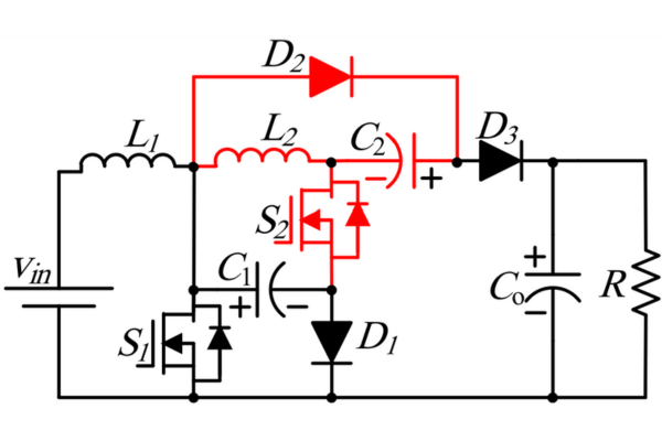 Optimizing Energy Management with Non-Isolated DC-DC Converters
04 February 20242894
 MediaTek, Qualcomm Announce Joining Russia Sanctions
10 March 20224295
 What is a Wireless Network Adapter?
01 June 20214843
 Msemitek Authorized Distributor | UTMEL Electronics
21 November 20232182
 What Are Wi-Fi Modules and Their Uses in IoT Today
04 June 2025723
 What is a Synchronous Motor?
16 March 20214935
 What is SPI (Serial Perripheral Interface)?
25 November 20214071
Lite-On Inc.
In Stock: 49663
United States
China
Canada
Japan
Russia
Germany
United Kingdom
Singapore
Italy
Hong Kong(China)
Taiwan(China)
France
Korea
Mexico
Netherlands
Malaysia
Austria
Spain
Switzerland
Poland
Thailand
Vietnam
India
United Arab Emirates
Afghanistan
Åland Islands
Albania
Algeria
American Samoa
Andorra
Angola
Anguilla
Antigua & Barbuda
Argentina
Armenia
Aruba
Australia
Azerbaijan
Bahamas
Bahrain
Bangladesh
Barbados
Belarus
Belgium
Belize
Benin
Bermuda
Bhutan
Bolivia
Bonaire, Sint Eustatius and Saba
Bosnia & Herzegovina
Botswana
Brazil
British Indian Ocean Territory
British Virgin Islands
Brunei
Bulgaria
Burkina Faso
Burundi
Cabo Verde
Cambodia
Cameroon
Cayman Islands
Central African Republic
Chad
Chile
Christmas Island
Cocos (Keeling) Islands
Colombia
Comoros
Congo
Congo (DRC)
Cook Islands
Costa Rica
Côte d’Ivoire
Croatia
Cuba
Curaçao
Cyprus
Czechia
Denmark
Djibouti
Dominica
Dominican Republic
Ecuador
Egypt
El Salvador
Equatorial Guinea
Eritrea
Estonia
Eswatini
Ethiopia
Falkland Islands
Faroe Islands
Fiji
Finland
French Guiana
French Polynesia
Gabon
Gambia
Georgia
Ghana
Gibraltar
Greece
Greenland
Grenada
Guadeloupe
Guam
Guatemala
Guernsey
Guinea
Guinea-Bissau
Guyana
Haiti
Honduras
Hungary
Iceland
Indonesia
Iran
Iraq
Ireland
Isle of Man
Israel
Jamaica
Jersey
Jordan
Kazakhstan
Kenya
Kiribati
Kosovo
Kuwait
Kyrgyzstan
Laos
Latvia
Lebanon
Lesotho
Liberia
Libya
Liechtenstein
Lithuania
Luxembourg
Macao(China)
Madagascar
Malawi
Maldives
Mali
Malta
Marshall Islands
Martinique
Mauritania
Mauritius
Mayotte
Micronesia
Moldova
Monaco
Mongolia
Montenegro
Montserrat
Morocco
Mozambique
Myanmar
Namibia
Nauru
Nepal
New Caledonia
New Zealand
Nicaragua
Niger
Nigeria
Niue
Norfolk Island
North Korea
North Macedonia
Northern Mariana Islands
Norway
Oman
Pakistan
Palau
Palestinian Authority
Panama
Papua New Guinea
Paraguay
Peru
Philippines
Pitcairn Islands
Portugal
Puerto Rico
Qatar
Réunion
Romania
Rwanda
Samoa
San Marino
São Tomé & Príncipe
Saudi Arabia
Senegal
Serbia
Seychelles
Sierra Leone
Sint Maarten
Slovakia
Slovenia
Solomon Islands
Somalia
South Africa
South Sudan
Sri Lanka
St Helena, Ascension, Tristan da Cunha
St. Barthélemy
St. Kitts & Nevis
St. Lucia
St. Martin
St. Pierre & Miquelon
St. Vincent & Grenadines
Sudan
Suriname
Svalbard & Jan Mayen
Sweden
Syria
Tajikistan
Tanzania
Timor-Leste
Togo
Tokelau
Tonga
Trinidad & Tobago
Tunisia
Turkey
Turkmenistan
Turks & Caicos Islands
Tuvalu
U.S. Outlying Islands
U.S. Virgin Islands
Uganda
Ukraine
Uruguay
Uzbekistan
Vanuatu
Vatican City
Venezuela
Wallis & Futuna
Yemen
Zambia
Zimbabwe