Product
 Brand
Brand Articles
 Tools
Tools
HBM4 and the Shift to Customized AI Memory: The Advanced Packaging Bottleneck
Quick answer
HBM4 is the sixth generation of High Bandwidth Memory and is defined by the JEDEC JESD270-4 family of standards. It doubles the external interface from 1,024 bits in HBM3 to 2,048 bits and increases the stack to 32 independent channels. The original JEDEC HBM4 release specified transfer rates up to 8 Gb/s and aggregate bandwidth up to about 2 TB/s per stack. Commercial 2026 products can operate above that baseline: Samsung reports up to 3.3 TB/s, while Micron reports more than 2.8 TB/s. Those are vendor product specifications, not the universal JEDEC baseline.
HBM4 also makes the base die more important because it must route a much wider interface and can support supplier- or customer-specific logic. That does not mean every HBM4 stack uses the same foundry node, contains general-purpose compute, or requires hybrid bonding. For procurement teams, HBM4 is a platform-qualified package component rather than a drop-in replacement for DDR5 or another HBM supplier's stack.
What the HBM4 standard actually specifies
JEDEC published the original JESD270-4 HBM4 standard in April 2025. The current revision is JESD270-4A, published later in 2025. When using a paid or controlled standard for design work, engineers should verify requirements against the current revision rather than relying only on the original press release or a vendor product page.
| JEDEC item | Original HBM4 release | Engineering meaning |
|---|---|---|
| External interface | 2,048 bits | Twice the width of HBM3/HBM3E, increasing routing, controller, base-die, package, and test complexity. |
| Channels | 32 independent channels, each with two pseudo-channels | More independent access paths improve concurrency, but the controller and workload still determine realized bandwidth. |
| Baseline transfer rate | Up to 8 Gb/s per pin | Commercial suppliers may qualify faster speed bins. A vendor result above 8 Gb/s is not a new JEDEC-wide baseline. |
| Aggregate bandwidth | Up to about 2 TB/s per stack | Theoretical bandwidth follows interface width and pin rate; sustained application bandwidth is lower and workload-dependent. |
| Stack configurations | 4-high, 8-high, 12-high, and 16-high using 24 Gb or 32 Gb dies | The standard permits up to 64 GB with 32 Gb dies in a 16-high stack; an actual vendor product may support fewer configurations. |
| Reliability feature | Directed Refresh Management (DRFM) | DRFM supports row-disturb mitigation and RAS. It should not be described as a complete security guarantee against every Rowhammer condition. |
The distinction between standard and product matters. At the 8 Gb/s JEDEC rate, 2,048 bits produce 2.048 TB/s of theoretical bandwidth. At 11.7 Gb/s the same interface produces about 2.995 TB/s, while 13 Gb/s produces about 3.328 TB/s. Samsung's maximum 3.3 TB/s figure therefore corresponds to its up-to-13-Gb/s capability, not its separately stated sustained 11.7-Gb/s operating point.
Why the logic base die matters
An HBM package stacks multiple DRAM core dies above a base die and connects the layers through through-silicon vias (TSVs). The base die routes signals and power between the DRAM stack and the host processor. With 2,048 data connections and more channels, HBM4 places more routing, power-delivery, test, and control demands on this layer.
Advanced logic processes can provide more routing density and room for control functions, but HBM4 does not mandate one base-die process node. Samsung's commercial HBM4 uses a 4 nm logic base die. SK hynix announced a development partnership with TSMC for an advanced-logic HBM4 base die, while its product and packaging choices remain supplier-specific. It is therefore inaccurate to label every HBM4 stack as universally using a 3 nm or 4 nm base die.
A logic base die also does not automatically turn HBM4 into processing-in-memory. It can contain power management, test, repair, routing, interface, or customer-specific logic without executing application workloads. Custom HBM is a co-design direction beyond standard products, and its functions must be confirmed from the specific accelerator and memory supplier.
2026 Samsung, SK hynix, and Micron products
By August 2026, HBM4 had moved beyond a future roadmap: Samsung, SK hynix, and Micron had each reported commercial production or mass shipments. Their public figures are not directly interchangeable because speed bins, capacity, stacking method, comparison baseline, and customer qualification differ.
| Supplier | Current public status | Speed and bandwidth | Capacity and stack | Important qualification |
|---|---|---|---|---|
| Samsung | Announced mass production and commercial customer shipments in 2026 | 11.7 Gb/s stable operation; capability up to 13 Gb/s; maximum 3.3 TB/s per stack | 24-36 GB in 12-high products; future 16-high option up to 48 GB | Uses 1c DRAM and a 4 nm logic base die; performance and efficiency figures are Samsung-reported |
| SK hynix | Reported mass shipments beginning in Q2 2026, with a production ramp in the second half | Development announcement stated above 10 Gb/s | Product configuration depends on the qualified customer platform | Uses Advanced MR-MUF packaging in its announced HBM4; Q2 status comes from company financial results |
| Micron | Began volume shipments of 36 GB 12-high HBM4 in Q1 2026 | Above 11 Gb/s and more than 2.8 TB/s per stack | 36 GB 12-high in production; 48 GB 16-high samples shipped to customers | Micron reports more than 20% power-efficiency improvement versus its HBM3E at the stated comparison point |
Use this table as a status map, not a cross-vendor purchasing specification. A complete comparison requires the exact orderable configuration, host interface qualification, thermal design, package stack-up, test conditions, availability window, and accelerator vendor approval.
Micro-bumps, molding, and hybrid bonding
HBM integration contains two related but different packaging problems. First, DRAM dies must be stacked and connected vertically through TSVs and die-to-die interconnects. Second, the completed HBM package must be integrated beside the accelerator through an interposer or another advanced package. TSMC CoWoS is one widely used platform for this second step, but it is not the only possible package architecture.
HBM4 does not universally require hybrid bonding. SK hynix's announced HBM4 uses Advanced MR-MUF, demonstrating that a current HBM4 product can use a mature micro-bump and molded-underfill route. Hybrid bonding remains important for future pitch, height, thermal, and stack-scaling goals, but adoption depends on product generation, supplier process, yield, and cost.
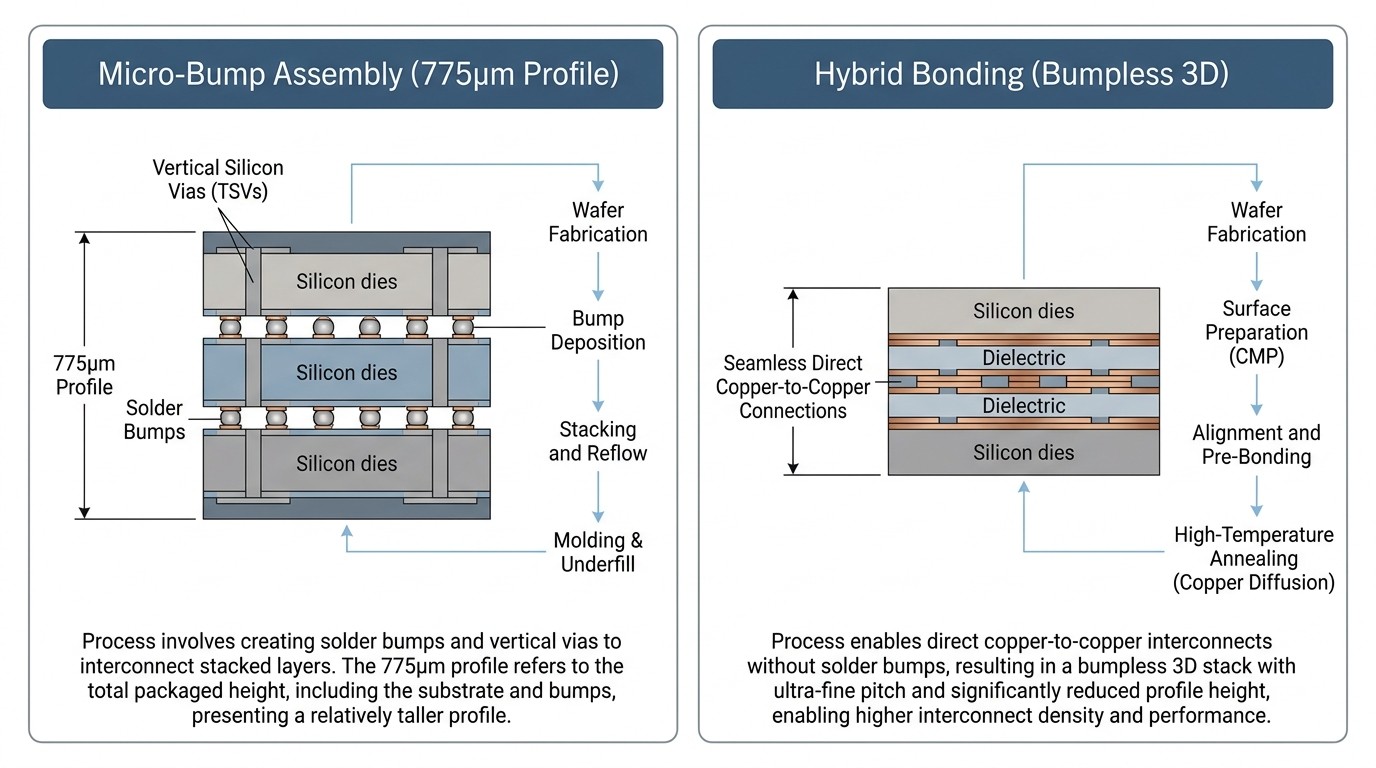
| Method | Connection | Why it is used | Main engineering constraints |
|---|---|---|---|
| Micro-bump with underfill or molding | Solder-based vertical interconnects between thinned dies | Established HBM manufacturing experience and current high-volume process options | Bump pitch, package height, warpage, underfill quality, thermal paths, and stacked-die yield |
| Hybrid bonding | Direct dielectric and copper-to-copper bonding without solder bumps | Finer interconnect pitch and reduced vertical separation for future scaling | Surface planarity, cleanliness, alignment, defect control, annealing, inspection, repair, and cost |
HBM4 compared with HBM3E and DDR5
DDR5, HBM3E, and HBM4 solve different system problems. Comparing a DIMM's bandwidth directly with one HBM stack can be misleading because a server uses multiple DDR5 channels, while an accelerator may integrate several HBM stacks in one package.
| Decision factor | Server DDR5 | HBM3E | HBM4 |
|---|---|---|---|
| System role | General-purpose CPU memory and large replaceable memory pools | Current accelerator memory for high-bandwidth AI and HPC platforms | Next-generation accelerator memory with a wider interface and more customization potential |
| Integration | DIMM or soldered memory connected through motherboard channels | Stacked DRAM integrated next to an accelerator through advanced packaging | Stacked DRAM with a 2,048-bit interface and a more complex base-die/package co-design |
| Serviceability | Socketed DIMMs can often be replaced or expanded within platform rules | Not field-replaceable separately from the accelerator package | Not field-replaceable separately from the qualified accelerator package |
| Selection authority | CPU/platform memory controller, motherboard QVL, module specifications, and firmware | Accelerator vendor and package qualification | Joint accelerator, memory, foundry, packaging, and system qualification |
HBM4 will not replace DDR5 in ordinary PCs and servers. HBM delivers very high local bandwidth but requires expensive, tightly integrated packaging and cannot provide the same modular capacity expansion. For a broader architecture discussion, see Will HBM replace DDR and become computer memory?
What HBM4 changes in the supply chain
HBM4 adds dependencies at several stages: advanced DRAM wafer fabrication, thinned-die and TSV processing, known-good-die screening, stack assembly, logic base-die manufacturing, package substrate or interposer capacity, accelerator integration, thermal design, and system qualification. A shortage or yield problem at any one of these stages can limit complete accelerator shipments even when enough DRAM bits exist.
That does not justify a universal claim that HBM consumes exactly three times the wafer capacity of DDR5, that 70%-90% of advanced DRAM capacity has moved to HBM, or that standard consumer DRAM is disappearing. Such ratios depend on die density, process generation, yield, stack height, allocation definitions, and time period. Current supplier statements show strong AI-memory demand, but they also describe demand growth for conventional server memory. Availability and pricing must therefore be tracked by product family, density, package, grade, supplier, region, and contract window.
NVIDIA's Vera Rubin platform illustrates the system-level scale: NVIDIA specifies 288 GB of HBM4 and up to 22 TB/s of memory bandwidth per Rubin GPU. That platform figure combines multiple HBM4 stacks; it should not be used as the specification of one HBM4 stack or as proof that one customer consumes most global supply.
Procurement and qualification checklist
HBM is normally sourced through an accelerator or custom-ASIC platform program, not selected from a distributor catalog as a generic substitute. Even for conventional DDR products, an alternative is not automatically a drop-in replacement.
Confirm the exact platform authority. Obtain the accelerator vendor's approved supplier, speed bin, capacity, package, firmware, and thermal requirements.
Separate standard compliance from qualification. JESD270-4A compliance does not prove that one supplier's HBM4 can replace another supplier's package in an existing design.
Check bandwidth at the right boundary. Distinguish pin rate, theoretical stack bandwidth, sustained stack bandwidth, total accelerator bandwidth, and application throughput.
Verify package and thermal details. Review stack height, substrate/interposer, warpage limits, heat-spreader interface, power delivery, cooling, and repair strategy.
Validate capacity and reliability. Confirm usable capacity, ECC/RAS behavior, DRFM implementation, temperature range, lifetime assumptions, and error reporting.
Track production status with dates. Distinguish samples, customer qualification, mass-production readiness, mass shipments, and volume availability for the target customer.
Use part-level controls for standard memory. For DDR4/DDR5 or other memory ICs, compare organization, voltage, timing, package, rank, SPD, temperature grade, lifecycle, and platform validation before approving an alternate.
What to ignore in HBM4 coverage
"3.3 TB/s is the HBM4 standard." It is a Samsung product maximum; the original JEDEC baseline is about 2 TB/s.
"All HBM4 uses a 3 nm or 4 nm base die." Base-die process choices are vendor- and product-specific.
"All HBM4 requires hybrid bonding." Current HBM4 can use established micro-bump and molding processes.
"HBM4 will replace DDR5." Their integration, serviceability, capacity model, cost, and system roles are different.
"A memory shortage has one fixed end date." Supply depends on product, process, packaging, qualification, customer allocation, and regional inventory.
Frequently asked questions
What is HBM4?
HBM4 is the sixth generation of High Bandwidth Memory. It uses stacked DRAM and a 2,048-bit external interface to provide high bandwidth close to AI accelerators and HPC processors.
What is the current JEDEC HBM4 standard?
JEDEC published JESD270-4 in April 2025, followed by revision JESD270-4A later in 2025. Engineering teams should use the current controlled revision for implementation and compliance decisions.
What is the standard bandwidth of HBM4?
The original JEDEC release specified up to 8 Gb/s across a 2,048-bit interface, or about 2 TB/s per stack. Commercial products can exceed this baseline; Samsung reports a maximum of 3.3 TB/s and Micron reports more than 2.8 TB/s.
Why does HBM4 use a logic base die?
The wider interface and larger channel count require dense routing, power delivery, test, repair, and control functions. A logic process can support those needs and enable product-specific functions, but the process node and functions vary by supplier.
Does HBM4 require hybrid bonding?
No. Hybrid bonding is a scaling option for finer pitch and lower vertical separation, but it is not a universal HBM4 requirement. SK hynix's announced HBM4 uses Advanced MR-MUF packaging.
What is the maximum HBM4 stack capacity?
The original JEDEC release supports up to 64 GB using 32 Gb dies in a 16-high stack. Current volume products may use lower capacities, such as 36 GB 12-high configurations, while 48 GB 16-high products may be samples or roadmap options depending on the supplier.
Is HBM4 in mass production?
Yes. By August 2026, Samsung, SK hynix, and Micron had each reported HBM4 mass production or mass shipments. Availability still depends on customer qualification, platform allocation, speed bin, and package configuration.
Can one HBM4 supplier replace another without redesign?
No automatic interchangeability should be assumed. Standards compliance does not guarantee identical electrical, mechanical, thermal, firmware, package, yield, or host-qualification behavior. The accelerator or ASIC platform owner must approve the exact configuration.
Conclusion
HBM4 is not simply faster HBM3E. Its 2,048-bit interface, 32 channels, logic base-die requirements, and package-level integration increase the importance of memory-controller, foundry, stacking, advanced-packaging, thermal, and system co-design. The most reliable way to evaluate HBM4 is to separate the JEDEC baseline from supplier-specific speed bins, separate product announcements from qualified volume availability, and treat sourcing as a platform-level engineering decision rather than a catalog substitution exercise.
References
 UTMEL
UTMEL
We are the professional distributor of electronic components, providing a large variety of products to save you a lot of time, effort, and cost with our efficient self-customized service. careful order preparation fast delivery service
 Power Semiconductor Procurement After the Nexperia Shake-Up—NXP for Stability, ON for Technology, or Nexperia for Value?UTMEL04 November 20254869
The recent supply chain turmoil surrounding Netherlands-based Nexperia has sent shockwaves through the global semiconductor industry, forcing procurement professionals to re-evaluate their sourcing strategies.
Read More AI Computing Power Gap: How Token Consumption is Reshaping Server Component SourcingUTMEL23 June 2026942
As global token consumption drives the transition to high-density 100kW+ AI data centers, power delivery networks require advanced Wide-Bandgap semiconductors (SiC/GaN) and high-capacitance MLCCs. This shift has triggered a component procurement crisis with lead times exceeding 24 weeks. To bypass shortages, hardware buyers must abandon just-in-time manufacturing and leverage independent global distributor networks to secure critical power and passive components.
Read More The BSPDN Revolution: Overcoming IR Drop in Sub-2nm GAAFET Nodes with Backside Power DeliveryUTMEL25 June 2026907
As semiconductor manufacturing enters the sub-2nm era, Backside Power Delivery Networks (BSPDN) are replacing traditional front-side routing to overcome critical IR drop bottlenecks. By separating power and signal delivery, chipmakers like Intel and TSMC drastically improve performance and density in GAAFET designs. However, this radical shift introduces manufacturing complexities, thermal challenges, and demands advanced packaging and power management solutions.
Read More Power Management ICs Trends 2026: AI Demand, Supply Risks, and Sourcing StrategiesUTMEL06 July 20261412
As AI server racks surpass 100kW by 2026, data centers are shifting toward wide-bandgap semiconductors like SiC and GaN. However, this demand has triggered a critical shortage of mature-node Power Management ICs (PMICs). To prevent production halts, sourcing teams must abandon 'just-in-time' models, implement proactive 'just-in-case' strategies, and rapidly qualify pin-to-pin alternative components to secure their supply chains.
Read More onsemi Synaptics Acquisition Impact: BOM Risk Checklist and Second-Source Strategy for Edge AI DesignsUTMEL27 July 2026337
The onsemi acquisition of Synaptics provides hardware program managers a 12-to-18-month window before potential product cancellations occur in mid-2027. This guide outlines how to audit BOM exposure across overlap and non-core product lines, calculate Last-Time-Buy volumes including hidden storage costs, establish proactive second-sourcing triggers, and implement supply chain monitoring to prevent line-down events.
Read More
Subscribe to Utmel !
![SLD8S22A]() SLD8S22A
SLD8S22ALittelfuse Inc.
![SPHV12-01ETG]() SPHV12-01ETG
SPHV12-01ETGLittelfuse Inc.
![TZY2Z060AC01R00]() TZY2Z060AC01R00
TZY2Z060AC01R00Murata Electronics
![SI8275GB-IS1]() SI8275GB-IS1
SI8275GB-IS1Silicon Labs
![MX25L25673GMI-10G]() MX25L25673GMI-10G
MX25L25673GMI-10GMacronix
![SML-S13RTT86]() SML-S13RTT86
SML-S13RTT86ROHM Semiconductor
![TZY2Z100AC01R00]() TZY2Z100AC01R00
TZY2Z100AC01R00Murata Electronics
![SD05C-7]() SD05C-7
SD05C-7Diodes Incorporated
![TEN-HS5]() TEN-HS5
TEN-HS5Traco Power
![UR030-006]() UR030-006
UR030-006Tripp Lite