

 Product
 Brand
Brand Articles
 Tools
Tools
Designing with AD5933: Datasheet, Pinout, and Impedance Spectroscopy Guide

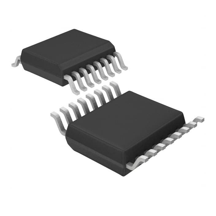
16 Termination 0.65mm Direct Digital Synthesis Automotive Series 16 Pin 16.776MHz 3.3V 16-SSOP (0.209, 5.30mm Width)
Unit Price: $33.287293
Ext Price: $33.29


16 Termination 0.65mm Direct Digital Synthesis Automotive Series 16 Pin 16.776MHz 3.3V 16-SSOP (0.209, 5.30mm Width)
The AD5933 is a high-precision impedance converter system that combines an on-board frequency generator with a 12-bit, 1 MSPS analog-to-digital converter (ADC) and a DSP engine for Discrete Fourier Transform (DFT) processing. It is designed to measure complex impedance by exciting an external load with a known frequency and processing the response to return real and imaginary data components.
- Executive Summary: What is the AD5933?
- 1. Technical Specifications & Performance Analysis
- 2. Pinout, Package, and Configuration
- 3. Design & Integration Guide (For Engineers & Makers)
- 4. Typical Applications & Use Cases
- 5. Alternatives and Cross-Reference Guide
- 6. Frequently Asked Questions (FAQ)
- Specifications
- Datasheet PDF
Executive Summary: What is the AD5933?
The AD5933 is a high-precision impedance converter system that combines an on-board frequency generator with a 12-bit, 1 MSPS analog-to-digital converter (ADC) and a DSP engine for Discrete Fourier Transform (DFT) processing. It is designed to measure complex impedance by exciting an external load with a known frequency and processing the response to return real and imaginary data components.
Market Position: High-performance integrated solution; the industry standard for portable impedance spectroscopy.
Top Features: 0.5% system accuracy, programmable frequency sweep via I2C, and an integrated temperature sensor for calibration.
Primary Audience: Ideal for medical device designers (BIA), industrial sensor engineers, and research scientists.
Supply Status: Active.
1. Technical Specifications & Performance Analysis
The AD5933 simplifies the complex task of network analysis by integrating the entire signal chain into a single 16-lead package.
1.1 Core Architecture (DDS & DSP)
The device utilizes a Direct Digital Synthesis (DDS) core to generate a precise excitation voltage. This signal is sent to an external impedance, and the resulting current is sampled by the 1 MSPS ADC. The on-board DSP engine performs a 1024-point DFT, which allows the user to read the real (R) and imaginary (I) register values directly, significantly reducing the computational load on the host microcontroller (STM32/Arduino).
1.2 Key Electrical Characteristics
Supply Voltage: Operates on a single supply from 2.7V to 5.5V, making it compatible with both low-power battery systems and standard 5V industrial rails.
Frequency Range: Supports programmable output frequencies from 1 kHz to 100 kHz.
Operating Temperature: Rated for -40°C to +125°C, suitable for harsh industrial and automotive environments.
Power Consumption: Optimized for precision rather than ultra-low power, though it features a power-down mode for energy savings.
1.3 Interfaces and Connectivity
The AD5933 communicates exclusively via a standard I2C interface. This interface controls the frequency sweep parameters (start frequency, frequency increment, and number of increments) and retrieves the processed impedance data.
2. Pinout, Package, and Configuration
Understanding the physical layout is critical for PCB routing, especially given the sensitive nature of analog impedance measurements.
2.1 Pin Configuration Guide
VOUT (Pin 6): The excitation signal output. Note that this signal has a DC bias.
VIN (Pin 5): The input for the current response from the measured load.
MCLK (Pin 8): External clock input. Using an external clock is highly recommended for measurements below 10 kHz to avoid spectral leakage.
SDA/SCL (Pins 15, 16): I2C data and clock lines for MCU communication.
2.2 Naming Convention & Ordering Codes
The AD5933 is typically found in the AD5933YRSZ format. - AD5933: Base part number. - Y: Temperature grade (-40°C to +125°C). - RS: Package code for SSOP. - Z: RoHS compliant/Lead-free.
2.3 Available Packages
| Package Type | Dimensions | Common Use Case |
|---|---|---|
| 16-Lead SSOP | 5.3mm x 6.2mm | Standard through-hole/SMT hybrid boards; easy to prototype. |
Note: The SSOP package is relatively hand-soldering friendly for advanced hobbyists but requires a steady hand and fine-tip iron.
3. Design & Integration Guide (For Engineers & Makers)
Pro Tip: Always buffer the VOUT pin. The internal output impedance of the AD5933 is high (up to 2.4kΩ) and can fluctuate, which introduces errors if driving a low-impedance load directly.
3.1 Hardware Implementation
Bypass Capacitors: Place 0.1µF and 10µF ceramic capacitors as close to the VDD pins as possible to minimize noise in the ADC.
PCB Layout: Use a solid ground plane. Keep the analog traces (VIN/VOUT) as short as possible to reduce parasitic capacitance, which can skew high-frequency results.
AC Coupling: Since VOUT has a DC bias of VDD/2, use a 10µF non-polarized capacitor in series with the output if measuring bio-samples or electrochemical cells to prevent polarization.
3.2 Common Design Challenges
Issue: DC Bias on Output -> Fix: Use an external AC coupling capacitor and a DC-bias re-insertion circuit if a specific bias is required.
Issue: Low Frequency Inaccuracy (<10kHz) -> Fix: Provide a lower frequency external MCLK. The internal 16.77MHz clock is too fast for low-frequency DFT windows.
Issue: Limited Dynamic Range -> Fix: The 12-bit ADC has limits. Use an external multiplexer (like the ADG849) to switch between different calibration resistors to match the "range" of your unknown load.
4. Typical Applications & Use Cases
The AD5933 is the "gold standard" for any application requiring portable frequency response analysis.
4.1 Real-World Example: Bioelectrical Impedance Analysis (BIA)
In smart scales or medical body composition analyzers, the AD5933 measures the impedance of body tissue. Because fat, muscle, and water have different electrical signatures at various frequencies, the AD5933 allows the device to calculate body fat percentage with high precision.
5. Alternatives and Cross-Reference Guide
If the AD5933 does not meet your specific cost or speed requirements, consider these alternatives:
AD5934: The direct "little brother." It is a lower-speed version (250 kSPS ADC) and is often more cost-effective for slower applications.
TI AFE4300: A specialized Analog Front End (AFE) specifically designed for weight and body composition, including integrated bio-impedance channels.
MAX30001: Best for ultra-low-power wearable medical applications focusing on ECG and Bio-Z.
Discrete STM32 Solution: For very low-cost projects, use an STM32 with internal DAC/ADC and perform the FFT in software, though this requires significantly more development time.
6. Frequently Asked Questions (FAQ)
Q: What is the difference between AD5933 and AD5934?
A: The AD5933 has a 1 MSPS ADC, while the AD5934 is limited to 250 kSPS. The AD5933 is better for higher frequency resolution and faster sweeps.
Q: Can AD5933 be used for battery-operated devices?
A: Yes, it operates down to 2.7V. However, ensure your power management can handle the current draw during active frequency sweeps.
Q: How do I calibrate the AD5933?
A: You must connect a known precision resistor (Gain Factor calculation) that is close to the expected impedance of your target load.
Q: Is the AD5933 suitable for automotive use?
A: Yes, its wide operating temperature range (-40°C to +125°C) makes it suitable for automotive sensor applications.
Specifications
Datasheet PDF
- Datasheets :
- ConflictMineralStatement :
![AT89C2051-24PU 8-bit Microcontroller: Circuit Diagram, Pinout, and Datasheet [Video&FAQ]](https://res.utmel.com/Images/Article/789f3a55-d7a1-41ca-9784-35cc175f9498.png) AT89C2051-24PU 8-bit Microcontroller: Circuit Diagram, Pinout, and Datasheet [Video&FAQ]
AT89C2051-24PU 8-bit Microcontroller: Circuit Diagram, Pinout, and Datasheet [Video&FAQ]16 February 202215046
 SI5351B-B I²C Clock Generator: Pinout, Features and Datasheet
22 December 20213215
 A Comprehensive Guide to LTC6952IUKG#TRPBF Clock Generator by Linear Technology/Analog Devices
06 March 2024326
 L7812CV Voltage Regulator: Pinout, Datasheet, and Schematic Diagram
05 July 202121397
 AD8233ACBZ-R7 Heart Rate Monitor: Low Noise, 20WLCSP Monitor and AD8233 Datasheet
21 January 20222196
 CCS811 Digital Gas Sensors: Datasheet, Pinout and Applications
27 July 20216209
 LSM9DS1TR Gyroscope Magnetometer 9 Axis Sensor I²C SPI Output: Datasheet, Features, and Pinout
07 April 20223068
 MIC2548 Programmable Current-Limit High-Side Switch: Pinout, Equivalent and Datasheet
04 March 2022609
 What is Tantalum Capacitor: Structure, Failure and Application Guide
14 April 202220809
 Optimizing Energy Exchange with Vehicle-to-Grid Technology
25 April 20233239
 A/D Converter: Basic Principle and Types
06 November 202020550
 Semiconductor Materials:Types, Properties and Production Process
21 October 202526312
 IOT-Based Anti-theft Handbag
29 August 20238012
 What is a Cascode Amplifier?
27 March 202515481
 Introduction to Photonic Integrated Circuits and PIC Technology
22 October 202515113
 The Rise of Semiconductor Stocks in the Tech Boom
05 December 20233995
Analog Devices Inc.
In Stock: 108
Minimum: 1 Multiples: 1
Qty
Unit Price
Ext Price
1
$33.287293
$33.29
10
$31.403107
$314.03
100
$29.625572
$2,962.56
500
$27.948653
$13,974.33
1000
$26.366654
$26,366.65
Not the price you want? Send RFQ Now and we'll contact you ASAP.
Inquire for More Quantity
![AD9834BRUZ]() AD9834BRUZ
AD9834BRUZAnalog Devices Inc.
![AD9850BRSZ]() AD9850BRSZ
AD9850BRSZAnalog Devices Inc.
![AD9832BRUZ]() AD9832BRUZ
AD9832BRUZAnalog Devices Inc.
![AD9834CRUZ]() AD9834CRUZ
AD9834CRUZAnalog Devices Inc.
![AD9833BRMZ-REEL7]() AD9833BRMZ-REEL7
AD9833BRMZ-REEL7Analog Devices Inc.
![AD9834BRUZ-REEL]() AD9834BRUZ-REEL
AD9834BRUZ-REELAnalog Devices Inc.
![AD5932YRUZ]() AD5932YRUZ
AD5932YRUZAnalog Devices Inc.
![AD9837BCPZ-RL7]() AD9837BCPZ-RL7
AD9837BCPZ-RL7Analog Devices Inc.
![AD9858BSVZ]() AD9858BSVZ
AD9858BSVZAnalog Devices Inc.
![AD9852ASVZ]() AD9852ASVZ
AD9852ASVZAnalog Devices Inc.


