
 Product
 Brand
Brand Articles
 Tools
Tools
DS1232N MicroMonitor Chip: Diagram, Pinout, and Datasheet

5V 8 Terminals 8-Pin DS1232 Voltage supervisor MicroMonitor™ Series 1 Channels Min 4.5V Max 5.5V
Unit Price: $10.076129
Ext Price: $10.08


5V 8 Terminals 8-Pin DS1232 Voltage supervisor MicroMonitor™ Series 1 Channels Min 4.5V Max 5.5V
The DS1232N MicroMonitorTM Chip keeps track of three critical microprocessor conditions: power, program execution, and external override. This article mainly introduces diagram, pinout, datasheet and other detailed information about Maxim Integrated DS1232N.
DS1232N Description
The DS1232N MicroMonitorTM Chip keeps track of three critical microprocessor conditions: power, program execution, and external override. The status of VCC is first monitored by a precision temperature-compensated reference and comparator circuit. An internal power fail signal is created when an out-of-tolerance event occurs, forcing a reset to the active state. The reset signals are kept active for a minimum of 250 milliseconds after VCC returns to an in-tolerance condition to allow the power supply and processor to recover.
The DS1232N's second function is to control the reset button. The DS1232 debounces the pushbutton input and ensures a 250 ms minimum active reset pulse width. A watchdog timer is the third feature. If the strobe input is not driven low before timeout, the DS1232's internal timer pushes the reset signals to the active state. The watchdog timer function can be programmed to operate at 150 milliseconds, 600 milliseconds, or 1.2 seconds.
DS1232N Pinout
The following figure is DS1232N Pinout.

Pinout
| Pin Number | Pin Name | Description |
| 1 | PBRST | Pushbutton Reset Input |
| 2 | TD | Time Delay Set |
| 3 | TOL | Selects 5% or 10% VCC Detect |
| 4 | GND | Ground |
| 5 | RST | Reset Output (Active High) |
| 6 | RST | Reset Output (Active Low, open drain) |
| 7 | ST | Strobe Input |
| 8 | VCC | +5 Volt Power |
| NC | No Connections |
DS1232N CAD Model
The followings show DS1232N Symbol, Footprint and 3D Model.

Symbol

Footprint

3D Model
DS1232N Features
• Halts and restarts an out-of-control microprocessor
• Holds microprocessor in check during power transients
• Automatically restarts microprocessor after power failure
• Monitors pushbutton for an external override
• Accurate 5% or 10% microprocessor power supply monitoring
• Eliminates the need for discrete components
• Space-saving, 8-pin mini-DIP
• Optional 16-pin SOIC surface-mount package
• Industrial temperature -40°C to +85°C available, designated N
Specifications
- TypeParameter
- Factory Lead Time6 Weeks
- Mount
In electronic components, the term "Mount" typically refers to the method or process of physically attaching or fixing a component onto a circuit board or other electronic device. This can involve soldering, adhesive bonding, or other techniques to secure the component in place. The mounting process is crucial for ensuring proper electrical connections and mechanical stability within the electronic system. Different components may have specific mounting requirements based on their size, shape, and function, and manufacturers provide guidelines for proper mounting procedures to ensure optimal performance and reliability of the electronic device.
Surface Mount, Through Hole - Mounting Type
The "Mounting Type" in electronic components refers to the method used to attach or connect a component to a circuit board or other substrate, such as through-hole, surface-mount, or panel mount.
Through Hole - Package / Case
refers to the protective housing that encases an electronic component, providing mechanical support, electrical connections, and thermal management.
8-DIP (0.300, 7.62mm) - Number of Pins8
- Watchdog TimersYes
- Operating Temperature
The operating temperature is the range of ambient temperature within which a power supply, or any other electrical equipment, operate in. This ranges from a minimum operating temperature, to a peak or maximum operating temperature, outside which, the power supply may fail.
-40°C~85°C TA - Packaging
Semiconductor package is a carrier / shell used to contain and cover one or more semiconductor components or integrated circuits. The material of the shell can be metal, plastic, glass or ceramic.
Tube - Series
In electronic components, the "Series" refers to a group of products that share similar characteristics, designs, or functionalities, often produced by the same manufacturer. These components within a series typically have common specifications but may vary in terms of voltage, power, or packaging to meet different application needs. The series name helps identify and differentiate between various product lines within a manufacturer's catalog.
MicroMonitor™ - Published1999
- JESD-609 Code
The "JESD-609 Code" in electronic components refers to a standardized marking code that indicates the lead-free solder composition and finish of electronic components for compliance with environmental regulations.
e3 - Pbfree Code
The "Pbfree Code" parameter in electronic components refers to the code or marking used to indicate that the component is lead-free. Lead (Pb) is a toxic substance that has been widely used in electronic components for many years, but due to environmental concerns, there has been a shift towards lead-free alternatives. The Pbfree Code helps manufacturers and users easily identify components that do not contain lead, ensuring compliance with regulations and promoting environmentally friendly practices. It is important to pay attention to the Pbfree Code when selecting electronic components to ensure they meet the necessary requirements for lead-free applications.
yes - Part Status
Parts can have many statuses as they progress through the configuration, analysis, review, and approval stages.
Active - Moisture Sensitivity Level (MSL)
Moisture Sensitivity Level (MSL) is a standardized rating that indicates the susceptibility of electronic components, particularly semiconductors, to moisture-induced damage during storage and the soldering process, defining the allowable exposure time to ambient conditions before they require special handling or baking to prevent failures
1 (Unlimited) - Number of Terminations8
- ECCN Code
An ECCN (Export Control Classification Number) is an alphanumeric code used by the U.S. Bureau of Industry and Security to identify and categorize electronic components and other dual-use items that may require an export license based on their technical characteristics and potential for military use.
EAR99 - TypeSimple Reset/Power-On Reset
- Terminal Finish
Terminal Finish refers to the surface treatment applied to the terminals or leads of electronic components to enhance their performance and longevity. It can improve solderability, corrosion resistance, and overall reliability of the connection in electronic assemblies. Common finishes include nickel, gold, and tin, each possessing distinct properties suitable for various applications. The choice of terminal finish can significantly impact the durability and effectiveness of electronic devices.
Matte Tin (Sn) - Additional Feature
Any Feature, including a modified Existing Feature, that is not an Existing Feature.
PUSHBUTTON RESET OPTION - Terminal Position
In electronic components, the term "Terminal Position" refers to the physical location of the connection points on the component where external electrical connections can be made. These connection points, known as terminals, are typically used to attach wires, leads, or other components to the main body of the electronic component. The terminal position is important for ensuring proper connectivity and functionality of the component within a circuit. It is often specified in technical datasheets or component specifications to help designers and engineers understand how to properly integrate the component into their circuit designs.
DUAL - Peak Reflow Temperature (Cel)
Peak Reflow Temperature (Cel) is a parameter that specifies the maximum temperature at which an electronic component can be exposed during the reflow soldering process. Reflow soldering is a common method used to attach electronic components to a circuit board. The Peak Reflow Temperature is crucial because it ensures that the component is not damaged or degraded during the soldering process. Exceeding the specified Peak Reflow Temperature can lead to issues such as component failure, reduced performance, or even permanent damage to the component. It is important for manufacturers and assemblers to adhere to the recommended Peak Reflow Temperature to ensure the reliability and functionality of the electronic components.
260 - Number of Functions1
- Supply Voltage
Supply voltage refers to the electrical potential difference provided to an electronic component or circuit. It is crucial for the proper operation of devices, as it powers their functions and determines performance characteristics. The supply voltage must be within specified limits to ensure reliability and prevent damage to components. Different electronic devices have specific supply voltage requirements, which can vary widely depending on their design and intended application.
5V - Terminal Pitch
The center distance from one pole to the next.
2.54mm - Time@Peak Reflow Temperature-Max (s)
Time@Peak Reflow Temperature-Max (s) refers to the maximum duration that an electronic component can be exposed to the peak reflow temperature during the soldering process, which is crucial for ensuring reliable solder joint formation without damaging the component.
30 - Base Part Number
The "Base Part Number" (BPN) in electronic components serves a similar purpose to the "Base Product Number." It refers to the primary identifier for a component that captures the essential characteristics shared by a group of similar components. The BPN provides a fundamental way to reference a family or series of components without specifying all the variations and specific details.
DS1232 - Output
In electronic components, the parameter "Output" typically refers to the signal or data that is produced by the component and sent to another part of the circuit or system. The output can be in the form of voltage, current, frequency, or any other measurable quantity depending on the specific component. The output of a component is often crucial in determining its functionality and how it interacts with other components in the circuit. Understanding the output characteristics of electronic components is essential for designing and troubleshooting electronic circuits effectively.
Open Drain, Push-Pull - Pin Count
a count of all of the component leads (or pins)
8 - Operating Supply Voltage
The voltage level by which an electrical system is designated and to which certain operating characteristics of the system are related.
5V - Power Supplies
an electronic circuit that converts the voltage of an alternating current (AC) into a direct current (DC) voltage.?
5V - Number of Channels1
- Max Supply Voltage
In general, the absolute maximum common-mode voltage is VEE-0.3V and VCC+0.3V, but for products without a protection element at the VCC side, voltages up to the absolute maximum rated supply voltage (i.e. VEE+36V) can be supplied, regardless of supply voltage.
5.5V - Min Supply Voltage
The minimum supply voltage (V min ) is explored for sequential logic circuits by statistically simulating the impact of within-die process variations and gate-dielectric soft breakdown on data retention and hold time.
4.5V - Operating Supply Current
Operating Supply Current, also known as supply current or quiescent current, is a crucial parameter in electronic components that indicates the amount of current required for the device to operate under normal conditions. It represents the current drawn by the component from the power supply while it is functioning. This parameter is important for determining the power consumption of the component and is typically specified in datasheets to help designers calculate the overall power requirements of their circuits. Understanding the operating supply current is essential for ensuring proper functionality and efficiency of electronic systems.
500μA - Nominal Supply Current
Nominal current is the same as the rated current. It is the current drawn by the motor while delivering rated mechanical output at its shaft.
500μA - Max Supply Current
Max Supply Current refers to the maximum amount of electrical current that a component can draw from its power supply under normal operating conditions. It is a critical parameter that ensures the component operates reliably without exceeding its thermal limits or damaging internal circuitry. Exceeding this current can lead to overheating, performance degradation, or failure of the component. Understanding this parameter is essential for designing circuits that provide adequate power while avoiding overload situations.
2mA - Adjustable Threshold
The "Adjustable Threshold" parameter in electronic components refers to the ability to manually set or modify the threshold level at which a specific function or operation is triggered. This feature allows users to customize the sensitivity or activation point of the component according to their specific requirements or preferences. By adjusting the threshold, users can fine-tune the performance of the component to suit different applications or environmental conditions. This flexibility in threshold adjustment can be particularly useful in various electronic devices and systems where precise control over triggering levels is necessary for optimal functionality.
NO - Reset
The "Reset" parameter in electronic components refers to a function that initializes or sets a device to a predefined state. It is often used to clear any temporary data, errors, or configurations that may have been stored during operation. The reset process can ensure that the device starts from a known good state, allowing for reliable performance in subsequent tasks. This parameter is critical in digital circuits and systems where proper initialization is necessary for correct functioning.
Active High/Active Low - Voltage - Threshold
Voltage - Threshold is a parameter in electronic components that refers to the minimum voltage level required to trigger a specific function or operation within the component. It is the critical voltage level at which the component transitions from one state to another, such as turning on or off. This threshold voltage is essential for ensuring the proper functioning of the component and is often specified in the component's datasheet. Understanding the voltage threshold is crucial for designing and troubleshooting electronic circuits to ensure that the component operates within its specified voltage range.
4.37V 4.62V - Number of Voltages Monitored
Voltage monitoring relays can detect not only under-voltages and over-voltages, but also voltage-related issues such as phase imbalances, phase loss, and phase sequence. Voltage monitoring relays are designed for either single-phase or three-phase systems.
1 - Reset Timeout
The "Reset Timeout" parameter in electronic components refers to the amount of time it takes for a device to reset or return to its default state after a specific event or condition. This parameter is crucial in ensuring the proper functioning and reliability of the component, as it determines how quickly the device can recover from a fault or error situation. A shorter reset timeout typically indicates a faster response time, while a longer reset timeout may allow for more thorough error recovery processes. Designers and engineers must carefully consider the reset timeout value to meet the requirements of the application and ensure optimal performance of the electronic component.
Adjustable/Selectable - Min Reset Threshold Voltage
Min Reset Threshold Voltage refers to the minimum voltage level at which a device, such as a microcontroller or a voltage supervisor, can reliably reset its internal state. When the supply voltage drops below this threshold, the device initiates a reset process to clear the current execution state and restore it to a known initial condition. This parameter is critical for ensuring proper operation during power fluctuations, preventing unintended behavior from occurring due to insufficient voltage.
4.5V - Max Reset Threshold Voltage
Max Reset Threshold Voltage refers to the maximum voltage level at which an electronic component, such as a voltage regulator or a reset circuit, will reset or initialize itself. When the input voltage exceeds this threshold, the component typically enters a defined state, often resetting its output or operational mode. It is a critical specification to ensure reliable operation and prevent unexpected behavior in electronic devices. This parameter is important for design considerations in applications where voltage fluctuations or spikes may occur.
4.74V - Undervoltage Threshold
During power up and power down, the UVLO function of the device has at least 0.1 V of hysteresis, but not more than 0.3 V. The UVLO function in power devices is a useful feature that enables robust system behavior across a wide range of operating conditions.
3.3V - Overvoltage Threshold
Overvoltages are all voltages that temporarily surpass the threshold value of the mains voltage. However, overvoltages can not only occur in the 230 V (normal household power supply voltage) mains, but can also reach the connected devices via telephone or aerial cables.
4.74V - Height2.03mm
- Length9.91mm
- Width7.87mm
- REACH SVHC
The parameter "REACH SVHC" in electronic components refers to the compliance with the Registration, Evaluation, Authorization, and Restriction of Chemicals (REACH) regulation regarding Substances of Very High Concern (SVHC). SVHCs are substances that may have serious effects on human health or the environment, and their use is regulated under REACH to ensure their safe handling and minimize their impact.Manufacturers of electronic components need to declare if their products contain any SVHCs above a certain threshold concentration and provide information on the safe use of these substances. This information allows customers to make informed decisions about the potential risks associated with using the components and take appropriate measures to mitigate any hazards.Ensuring compliance with REACH SVHC requirements is essential for electronics manufacturers to meet regulatory standards, protect human health and the environment, and maintain transparency in their supply chain. It also demonstrates a commitment to sustainability and responsible manufacturing practices in the electronics industry.
Unknown - Radiation Hardening
Radiation hardening is the process of making electronic components and circuits resistant to damage or malfunction caused by high levels of ionizing radiation, especially for environments in outer space (especially beyond the low Earth orbit), around nuclear reactors and particle accelerators, or during nuclear accidents or nuclear warfare.
No - RoHS Status
RoHS means “Restriction of Certain Hazardous Substances” in the “Hazardous Substances Directive” in electrical and electronic equipment.
ROHS3 Compliant - Lead Free
Lead Free is a term used to describe electronic components that do not contain lead as part of their composition. Lead is a toxic material that can have harmful effects on human health and the environment, so the electronics industry has been moving towards lead-free components to reduce these risks. Lead-free components are typically made using alternative materials such as silver, copper, and tin. Manufacturers must comply with regulations such as the Restriction of Hazardous Substances (RoHS) directive to ensure that their products are lead-free and environmentally friendly.
Lead Free
DS1232N Micromonitor Block Diagram
The following is DS1232N Micromonitor Block Diagram.

Micromonitor Block Diagram
DS1232N Pushbutton Reset
The DS1232N Pushbutton Reset is shown as follows.

Pushbutton Reset
DS1232N Watchdog Timer
The following figure is DS1232N Watchdog Timer.

Watchdog Timer
DS1232N Alternatives
| Part Number | Description | Manufacturer |
| MAX1232CPAPOWER CIRCUITS | 1-CHANNEL POWER SUPPLY MANAGEMENT CKT, PDIP8, PLASTIC, DIP-8 | Rochester Electronics LLC |
| DS1232LP+POWER CIRCUITS | Power Supply Support Circuit, Fixed, 1 Channel, +4.37/4.62VV, CMOS, PDIP8, 0.300 INCH, DIP-8 | Maxim Integrated Products |
| MAX1232CPA+POWER CIRCUITS | Power Supply Management Circuit, Fixed, 1 Channel, +4.37/4.62VV, CMOS, PDIP8, PLASTIC, DIP-8 | Maxim Integrated Products |
| DS1232LPPOWER CIRCUITS | Power Supply Support Circuit, Fixed, 1 Channel, +4.37/4.62VV, CMOS, PDIP8, 0.300 INCH, DIP-8 | Dallas Semiconductor |
| DS1232POWER CIRCUITS | Power Supply Support Circuit, Fixed, 1 Channel, +4.37/4.62VV, CMOS, PDIP8, 0.300 INCH, DIP-8 | Dallas Semiconductor |
| DS1232LPN+POWER CIRCUITS | Power Supply Management Circuit, Fixed, 1 Channel, +4.37/4.62VV, CMOS, PDIP8, 0.300 INCH, ROHS COMPLIANT, DIP-8 | Maxim Integrated Products |
DS1232N Applications
• Power Supply
• Software Execution
• External Override
• Pushbutton Reset Control
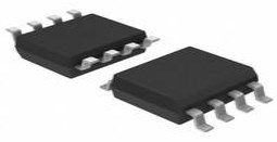
DS1232N Package
The DS1232N Package is shown as follows.

Package
DS1232N Manufacturer
Analog Devices' Maxim Integrated designs, manufactures and sells analog and mixed-signal integrated circuits for automotive, industrial, communications, consumer, and computing applications. Power and battery management ICs, sensors, analog ICs, interface ICs, communications solutions, digital ICs, embedded security, and microcontrollers are all part of Maxim's product line. The company includes design centers, manufacturing facilities, and sales offices all around the world, with its headquarters in San Jose, California.
Trend Analysis
Datasheet PDF
- Application Notes :
- Datasheets :
- ConflictMineralStatement :
How is the status of VCC first monitored?
Precision temperature-compensated reference and comparator circuit.
When is an internal power fail signal created?
An out-of-tolerance event occurs.
How long are reset signals kept active after VCC returns to an in-tolerance condition?
250 milliseconds.
What is the second function of the DS1232N?
Control the reset button.
What does the DS1232 ensure?
250 ms minimum active reset pulse width.
What is the third feature of the DS1232N MicroMonitorTM Chip?
Watchdog timer.
What input does the DS1232s internal timer push to the active state?
Strobe.
 STM32H723VGT6 Datasheet Guide: How to Find & Interpret Technical Documentation
05 July 20251510
 TL081 Single Op-Amp : Pinout, Application and Datasheet
23 July 202110074
 Top Tips for Getting Started with EP2C5T144C8N FPGA Boards
23 July 2025177
![TYN616 Thyristors SCRs 600V 16A TO-220AB[FAQ]: Pinout, Features, and Datasheet](https://res.utmel.com/Images/Article/d3c7ac52-c798-439a-843d-1bc66885c4d3.png) TYN616 Thyristors SCRs 600V 16A TO-220AB[FAQ]: Pinout, Features, and Datasheet
TYN616 Thyristors SCRs 600V 16A TO-220AB[FAQ]: Pinout, Features, and Datasheet04 May 20226654
 BQ51050BRHLR: Wireless Power Receiver
12 March 20221174
 FLIRE5 Infrared Cameras: Datasheet, Price and Benefits
03 August 20211409
 MCP2221 Driver: USB 2.0 to I2C/UART, Datasheet, Pinout
20 December 20212737
 In-Depth Analysis of the Microchip PIC16LC622 Microcontroller
28 February 2024162
 The Introduction of Car Fuse
09 October 20216128
 What Determines the Maximum Operating Frequency of a Diode?
29 June 202211961
 Protect USB Ports From Nefarious USB Killers
15 November 20191593
 Good news | Warm Congratulations to UTMEL Electronic for Obtaining the Letter of Authorization from XKB Connectivity
21 July 20253298
 Is there a Limit to the Chip Process Node?
02 November 202119507
 How does a Resettable Fuse Work?
26 August 202036307
 The Art of Microchips: A Journey from Sand to Silicon
12 September 20233842
 Understanding the Crystal Oscillator: Construction, Working Principles and Applications
08 July 20243212
Maxim Integrated
In Stock: 15000
Minimum: 1 Multiples: 1
Qty
Unit Price
Ext Price
1
$10.076129
$10.08
10
$9.505782
$95.06
100
$8.967719
$896.77
500
$8.460112
$4,230.06
1000
$7.981238
$7,981.24
Not the price you want? Send RFQ Now and we'll contact you ASAP.
Inquire for More Quantity
![MAX706SCSA]() MAX706SCSA
MAX706SCSAMaxim Integrated
![MAX16007ETP T]() MAX16007ETP T
MAX16007ETP TMaxim Integrated
![MAX6338AUB T]() MAX6338AUB T
MAX6338AUB TMaxim Integrated
![MAX793TCSE T]() MAX793TCSE T
MAX793TCSE TMaxim Integrated
![MAX6316LUK29AX T]() MAX6316LUK29AX T
MAX6316LUK29AX TMaxim Integrated
![MAX705CSA T]() MAX705CSA T
MAX705CSA TMaxim Integrated
![MAX690SESA T]() MAX690SESA T
MAX690SESA TMaxim Integrated
![MAX704RCSA]() MAX704RCSA
MAX704RCSAMaxim Integrated
![MAX708CUA T]() MAX708CUA T
MAX708CUA TMaxim Integrated
![MAX709TESA T]() MAX709TESA T
MAX709TESA TMaxim Integrated


