
 Product
 Brand
Brand Articles
 Tools
Tools
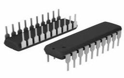
DS17285E-3+ Real Time Clock: Pinout, Equivalent and Datasheet


28 Terminations 3V 28 Pin DS17285 Real Time Clocks 0.032MHz
The DS17285E-3+ is a successor to the DS1285 real-time clock (RTC). The device provides 18 bytes of real-time clock/calendar, alarm, and control/status registers and 114 bytes of nonvolatile battery-backed RAM. The device also provides additional extended RAM in either 2kbytes. The device is accessed by a multiplexed address/data bus. Furthermore, Huge range of Semiconductors, Capacitors, Resistors and IcS in stock. Welcome RFQ.

What is RTC(REAL TIME CLOCK) ? | RTC Working | RTC Uses | RTC Diagram | (CMOS)Clock In Computer
DS17285E-3+ Pinout
The following figure is the diagram of DS17285E-3+ Pinout.

Pinout
DS17285E-3+ CAD Model
The followings are DS17285E-3+ Symbol and Footprint.

Symbol

Footprint
DS17285E-3+ Description
The DS17285E-3+ Real Time Clock is designed to be successors to the industry-standard DS12885 and DS12887. The DS17285E-3+ (hereafter referred to as the DS17x85) provides a real-time clock/calendar, one time-of-day alarm, three maskable interrupts with a common interrupt output, a programmable square wave, and 114 bytes of battery-backed NV SRAM. The DS17x85 also incorporates a number of enhanced functions including a silicon serial number, power-on/off control circuitry, and 2k, 4k, or 8kbytes of battery-backed NV SRAM. The DS17x85 power-control circuitry allows the system to be powered on by an external stimulus such as a keyboard or by a time-and-date (wake-up) alarm. The PWR output pin is triggered by one or either of these events, and is used to turn on an external power supply. The PWR pin is under software control, so that when a task is complete, the system power can then be shut down.
For all devices, the date at the end of the month is automatically adjusted for months with fewer than 31 days, including correction for leap years. It also operates in either 24-hour or 12-hour format with an AM/PM indicator. A precision temperature-compensated circuit monitors the status of VCC. If a primary power failure is detected, the device automatically switches to a backup supply. A lithium coin cell battery can be connected to the VBAT input pin on the DS17285E-3+ to maintain time and date operation when primary power is absent. The DS17285E-3+ includes a VBAUX input used to power auxiliary functions such as PWR control. The device is accessed through a multiplexed byte-wide interface.
This article will introduce DS17285E-3+ systematically from its features, pinout to its specifications, applications, also including DS17285E-3+ datasheet and so much more.
DS17285E-3+ Features
● RTC Counts Seconds, Minutes, Hours, Day, Date, Month, and Year with Leap Year Compensation Through 2099
● Optional +3.0V or +5.0V Operation
● SMI Recovery Stack
● 64-Bit Silicon Serial Number
● Power-Control Circuitry Supports System Power-On from Date/Time Alarm or Key Closure
● Crystal Select Bit Allows Operation with 6pF or 12.5pF Crystal
● 12-Hour or 24-Hour Clock with AM and PM in 12-Hour Mode
● 114 Bytes of General-Purpose, Battery-Backed NV SRAM
● Extended Battery-Backed NV SRAM: 2048 Bytes
● RAM Clear Function
● Interrupt Output with Six Independently Maskable Interrupt Flags
● Time-of-Day Alarm Once per Second to Once per Day
● End of Clock Update Cycle Flag
● Programmable Square-Wave Output
● Automatic Power-Fail Detect and Switch Circuitry
● Available in PDIP, SO, or TSOP Package
● Optional Industrial Temperature Range Available
● Underwriters Laboratory (UL) Recognized
Specifications
- TypeParameter
- Mounting Type
The "Mounting Type" in electronic components refers to the method used to attach or connect a component to a circuit board or other substrate, such as through-hole, surface-mount, or panel mount.
Surface Mount - Package / Case
refers to the protective housing that encases an electronic component, providing mechanical support, electrical connections, and thermal management.
28-TSSOP (0.465, 11.80mm Width) - Surface Mount
having leads that are designed to be soldered on the side of a circuit board that the body of the component is mounted on.
YES - Operating Temperature
The operating temperature is the range of ambient temperature within which a power supply, or any other electrical equipment, operate in. This ranges from a minimum operating temperature, to a peak or maximum operating temperature, outside which, the power supply may fail.
0°C~70°C - Packaging
Semiconductor package is a carrier / shell used to contain and cover one or more semiconductor components or integrated circuits. The material of the shell can be metal, plastic, glass or ceramic.
Tray - Published2012
- JESD-609 Code
The "JESD-609 Code" in electronic components refers to a standardized marking code that indicates the lead-free solder composition and finish of electronic components for compliance with environmental regulations.
e0 - Part Status
Parts can have many statuses as they progress through the configuration, analysis, review, and approval stages.
Obsolete - Moisture Sensitivity Level (MSL)
Moisture Sensitivity Level (MSL) is a standardized rating that indicates the susceptibility of electronic components, particularly semiconductors, to moisture-induced damage during storage and the soldering process, defining the allowable exposure time to ambient conditions before they require special handling or baking to prevent failures
3 (168 Hours) - Number of Terminations28
- ECCN Code
An ECCN (Export Control Classification Number) is an alphanumeric code used by the U.S. Bureau of Industry and Security to identify and categorize electronic components and other dual-use items that may require an export license based on their technical characteristics and potential for military use.
EAR99 - TypeClock/Calendar
- Terminal Finish
Terminal Finish refers to the surface treatment applied to the terminals or leads of electronic components to enhance their performance and longevity. It can improve solderability, corrosion resistance, and overall reliability of the connection in electronic assemblies. Common finishes include nickel, gold, and tin, each possessing distinct properties suitable for various applications. The choice of terminal finish can significantly impact the durability and effectiveness of electronic devices.
Tin/Lead (Sn/Pb) - HTS Code
HTS (Harmonized Tariff Schedule) codes are product classification codes between 8-1 digits. The first six digits are an HS code, and the countries of import assign the subsequent digits to provide additional classification. U.S. HTS codes are 1 digits and are administered by the U.S. International Trade Commission.
8542.39.00.01 - Voltage - Supply
Voltage - Supply refers to the range of voltage levels that an electronic component or circuit is designed to operate with. It indicates the minimum and maximum supply voltage that can be applied for the device to function properly. Providing supply voltages outside this range can lead to malfunction, damage, or reduced performance. This parameter is critical for ensuring compatibility between different components in a circuit.
2.7V~3.7V - Terminal Position
In electronic components, the term "Terminal Position" refers to the physical location of the connection points on the component where external electrical connections can be made. These connection points, known as terminals, are typically used to attach wires, leads, or other components to the main body of the electronic component. The terminal position is important for ensuring proper connectivity and functionality of the component within a circuit. It is often specified in technical datasheets or component specifications to help designers and engineers understand how to properly integrate the component into their circuit designs.
DUAL - Peak Reflow Temperature (Cel)
Peak Reflow Temperature (Cel) is a parameter that specifies the maximum temperature at which an electronic component can be exposed during the reflow soldering process. Reflow soldering is a common method used to attach electronic components to a circuit board. The Peak Reflow Temperature is crucial because it ensures that the component is not damaged or degraded during the soldering process. Exceeding the specified Peak Reflow Temperature can lead to issues such as component failure, reduced performance, or even permanent damage to the component. It is important for manufacturers and assemblers to adhere to the recommended Peak Reflow Temperature to ensure the reliability and functionality of the electronic components.
240 - Supply Voltage
Supply voltage refers to the electrical potential difference provided to an electronic component or circuit. It is crucial for the proper operation of devices, as it powers their functions and determines performance characteristics. The supply voltage must be within specified limits to ensure reliability and prevent damage to components. Different electronic devices have specific supply voltage requirements, which can vary widely depending on their design and intended application.
3V - Terminal Pitch
The center distance from one pole to the next.
0.55mm - Reach Compliance Code
Reach Compliance Code refers to a designation indicating that electronic components meet the requirements set by the Registration, Evaluation, Authorization, and Restriction of Chemicals (REACH) regulation in the European Union. It signifies that the manufacturer has assessed and managed the chemical substances within the components to ensure safety and environmental protection. This code is vital for compliance with regulations aimed at minimizing risks associated with hazardous substances in electronic products.
not_compliant - Time@Peak Reflow Temperature-Max (s)
Time@Peak Reflow Temperature-Max (s) refers to the maximum duration that an electronic component can be exposed to the peak reflow temperature during the soldering process, which is crucial for ensuring reliable solder joint formation without damaging the component.
20 - Base Part Number
The "Base Part Number" (BPN) in electronic components serves a similar purpose to the "Base Product Number." It refers to the primary identifier for a component that captures the essential characteristics shared by a group of similar components. The BPN provides a fundamental way to reference a family or series of components without specifying all the variations and specific details.
DS17285 - Pin Count
a count of all of the component leads (or pins)
28 - JESD-30 Code
JESD-30 Code refers to a standardized descriptive designation system established by JEDEC for semiconductor-device packages. This system provides a systematic method for generating designators that convey essential information about the package's physical characteristics, such as size and shape, which aids in component identification and selection. By using JESD-30 codes, manufacturers and engineers can ensure consistency and clarity in the specification of semiconductor packages across various applications and industries.
R-PDSO-G28 - Qualification Status
An indicator of formal certification of qualifications.
Not Qualified - Power Supplies
an electronic circuit that converts the voltage of an alternating current (AC) into a direct current (DC) voltage.?
3V - Interface
In electronic components, the term "Interface" refers to the point at which two different systems, devices, or components connect and interact with each other. It can involve physical connections such as ports, connectors, or cables, as well as communication protocols and standards that facilitate the exchange of data or signals between the connected entities. The interface serves as a bridge that enables seamless communication and interoperability between different parts of a system or between different systems altogether. Designing a reliable and efficient interface is crucial in ensuring proper functionality and performance of electronic components and systems.
Parallel - Memory Size
The memory capacity is the amount of data a device can store at any given time in its memory.
2KB - Clock Frequency
Clock frequency, also known as clock speed, refers to the rate at which a processor or electronic component can execute instructions. It is measured in hertz (Hz) and represents the number of cycles per second that the component can perform. A higher clock frequency typically indicates a faster processing speed and better performance. However, it is important to note that other factors such as architecture, efficiency, and workload also play a significant role in determining the overall performance of a component. In summary, clock frequency is a crucial parameter that influences the speed and efficiency of electronic components in processing data and executing tasks.
0.032MHz - External Data Bus Width
The External Data Bus Width refers to the number of bits that can be transmitted simultaneously between a microprocessor and external components, such as memory or peripherals. It determines the amount of data that can be transferred in a single clock cycle. A wider data bus allows for faster data transfer rates and can improve overall system performance. Common data bus widths include 8-bit, 16-bit, 32-bit, and 64-bit, with larger widths generally offering higher throughput but requiring more complex circuitry. The External Data Bus Width is an important parameter to consider when designing or evaluating electronic components to ensure compatibility and optimal performance.
8 - Number of Timers1
- Time Format
Time is based on a 24 hour system. This is frequently referred to as "military time". The 24 hour system is the default format.
HH:MM:SS (12/24 hr) - Date Format
The international standard recommends writing the date as year, then month, then the day:?YYYY-MM-DD.
YY-MM-DD-dd - Current - Timekeeping (Max)
The parameter "Current - Timekeeping (Max)" in electronic components refers to the maximum current that a device can draw while performing timekeeping functions. Timekeeping functions typically involve maintaining accurate time and date information within a device, such as in a real-time clock (RTC) or a microcontroller with a built-in clock. The maximum current specified for timekeeping is important for determining the power consumption of the device when it is in standby or low-power modes, as excessive current draw can drain the battery quickly. Designers need to consider this parameter when selecting components for battery-powered devices to ensure efficient power management and longer battery life.
2mA @ 2.7V~3.7V - Time-Min
Time-Min is a parameter in electronic components that refers to the minimum amount of time required for a specific operation or function to be completed. This parameter is crucial in determining the speed and efficiency of the component's performance. It is often specified in datasheets and technical documentation to provide users with information on the component's timing characteristics. Understanding the "Time-Min" parameter is essential for designing and integrating electronic components into circuits to ensure proper functionality and timing synchronization.
SECONDS - Interrupt Capability
Returns the number of interrupts available for a specified hardware device and interrupt type.
Y - Voltage - Supply, Battery
Voltage - Supply, Battery refers to the nominal voltage level provided by a battery to power electronic components or circuits. It indicates the standard voltage output that a battery can deliver under typical operating conditions. This parameter is crucial for ensuring compatibility between the battery and the electronic device, as it affects performance and functionality. The voltage supply rating helps in selecting the appropriate battery for specific applications, ensuring that the device operates efficiently and safely.
2.5V~3.7V - Volatile
In the context of electronic components, the term "Volatile" refers to a type of memory or storage that requires power to maintain the stored data. When power is removed or lost, the data stored in volatile memory is also lost. This is in contrast to non-volatile memory, which retains data even when power is turned off.Volatile memory is commonly used in devices like RAM (Random Access Memory) in computers, where data needs to be quickly accessed and modified. However, it is not suitable for long-term storage of important data as it requires continuous power supply to retain information.Overall, the volatile nature of this type of memory makes it fast and efficient for temporary data storage and processing, but it is not ideal for permanent data storage due to its dependency on power supply.
YES - Features
In the context of electronic components, the term "Features" typically refers to the specific characteristics or functionalities that a particular component offers. These features can vary depending on the type of component and its intended use. For example, a microcontroller may have features such as built-in memory, analog-to-digital converters, and communication interfaces like UART or SPI.When evaluating electronic components, understanding their features is crucial in determining whether they meet the requirements of a particular project or application. Engineers and designers often look at features such as operating voltage, speed, power consumption, and communication protocols to ensure compatibility and optimal performance.In summary, the "Features" parameter in electronic components describes the unique attributes and capabilities that differentiate one component from another, helping users make informed decisions when selecting components for their electronic designs.
Alarm, Daylight Savings, Leap Year, NVSRAM, Square Wave Output - Length11.8mm
- Height Seated (Max)
Height Seated (Max) is a parameter in electronic components that refers to the maximum allowable height of the component when it is properly seated or installed on a circuit board or within an enclosure. This specification is crucial for ensuring proper fit and alignment within the overall system design. Exceeding the maximum seated height can lead to mechanical interference, electrical shorts, or other issues that may impact the performance and reliability of the electronic device. Manufacturers provide this information to help designers and engineers select components that will fit within the designated space and function correctly in the intended application.
1.2mm - Width8mm
- RoHS Status
RoHS means “Restriction of Certain Hazardous Substances” in the “Hazardous Substances Directive” in electrical and electronic equipment.
Non-RoHS Compliant - Lead Free
Lead Free is a term used to describe electronic components that do not contain lead as part of their composition. Lead is a toxic material that can have harmful effects on human health and the environment, so the electronics industry has been moving towards lead-free components to reduce these risks. Lead-free components are typically made using alternative materials such as silver, copper, and tin. Manufacturers must comply with regulations such as the Restriction of Hazardous Substances (RoHS) directive to ensure that their products are lead-free and environmentally friendly.
Contains Lead
DS17285E-3+ Functional Block Diagram
The following is the Functional Diagram of DS17285E-3+.

Functional Diagram
DS17285E-3+ Typical Operating Circuit
The following diagram shows the DS17285E-3+ Typical Operating Circuit.

Typical Operating Circuit
DS17285E-3+ Equivalent
| Model number | Manufacturer | Description |
| DS17285EN-5 | Dallas Semiconductor | Real Time Clock, Volatile, 1 Timer(s), CMOS, PDSO28, TSOP-28 |
| DS17285E-3 | Dallas Semiconductor | Real Time Clock, Volatile, 1 Timer(s), CMOS, PDSO28, TSOP-28 |
| DS17285E-5 | Rochester Electronics LLC | 1 TIMER(S), REAL TIME CLOCK, PDSO28, TSOP-28 |
| DS17285EN-3 | Maxim Integrated Products | Real Time Clock, Volatile, 1 Timer(s), CMOS, PDSO28, TSOP-28 |
Parts with Similar Specs
DS17285E-3+ Applications
● Embedded Systems
● Utility Meters
● Security Systems
● Network Hubs, Bridges, and Routers
DS17285E-3+ Package
The following diagrams show the DS17285E-3+ Package.

Top View

Side View

Detail A
DS17285E-3+ Manufacturer
The market is evolving. The rules are changing. To keep your time to market short, you need integration at every level—from silicon to the supply chain. Count on Maxim Integrated to help you overcome design and architectural challenges, with integrated solutions for the industrial, medical, consumer, automotive, energy, computing, and communications realms. Maxim Integrated is also your source for power, interface, and even digital products that work in the analog world. And they're glad to support you with reference designs, tools, technical documents, packaging, and more. We invite you to explore their latest analog integration offerings.
Datasheet PDF
- Datasheets :
- Application Notes :
- PCN Obsolescence/ EOL :
- ConflictMineralStatement :
How many pins of DS17285E-3+?
28 Pins.
What’s the operating temperature of DS17285E-3+?
0°C~70°C.
What’s the supply voltage of DS17285E-3+?
2.7V~3.7V.
What is the essential property of the DS17285E-3+?
The DS17285E-3+ is a successor to the DS1285 real-time clock (RTC). The device provides 18 bytes of real-time clock/calendar, alarm, and control/status registers and 114 bytes of nonvolatile battery-backed RAM.
![BTA41600B Triacs: Circuits, Pinout, and Datasheet [Video&FAQ]](https://res.utmel.com/Images/Article/5169be14-70e1-4baf-b0ca-11d2e3847bd3.png) BTA41600B Triacs: Circuits, Pinout, and Datasheet [Video&FAQ]
BTA41600B Triacs: Circuits, Pinout, and Datasheet [Video&FAQ]16 December 202126855
 rg6 vs rg11 Coaxials: What’s the Difference?
31 March 202257653
 STM32F407VGT6 Microcontroller: 168MHz,100-LQFP, Pinout and Features
07 February 202213571
 TSOP4838: Description, datasheet, and features
15 March 20224321
 LIS2DE12TR Motion Sensor: Three-Axis Accelerometer, Datasheet, Application Hint
26 February 20222236
 ST2001FX Transistor: Datasheet, Pinout, Application
09 August 20211904
 ATTINY2313-20PU AVR ATtiny Microcontroller 20MHz 20-pin DIP: Datasheet, Pinout, and Features
25 February 20222100
 IRF520 MOSFET: Pinout, Datasheet, Test Circuit, and Equivalents
31 July 202118072
 How to Address IoT Eco-security in the Era of Digital Transformation?
22 April 2022599
 What is a Force Sensor?
19 April 202112017
 What is the Difference between MOM, MIM and MOS Capacitors?
17 April 202569277
 Semiconductor Material Industry Guide
21 January 20226950
 An Overview of 12 Important CPU Specs
18 December 202112540
 Characteristics, Types, and Functions of Electrolytic Capacitors
17 October 202510454
 Understanding Machine Vision and Visual Sensor
27 September 20212104
 Stanford Engineer Sheds Light on Semiconductors: Their Importance, Challenges, and Future
22 September 20231948
Maxim Integrated
In Stock
United States
China
Canada
Japan
Russia
Germany
United Kingdom
Singapore
Italy
Hong Kong(China)
Taiwan(China)
France
Korea
Mexico
Netherlands
Malaysia
Austria
Spain
Switzerland
Poland
Thailand
Vietnam
India
United Arab Emirates
Afghanistan
Åland Islands
Albania
Algeria
American Samoa
Andorra
Angola
Anguilla
Antigua & Barbuda
Argentina
Armenia
Aruba
Australia
Azerbaijan
Bahamas
Bahrain
Bangladesh
Barbados
Belarus
Belgium
Belize
Benin
Bermuda
Bhutan
Bolivia
Bonaire, Sint Eustatius and Saba
Bosnia & Herzegovina
Botswana
Brazil
British Indian Ocean Territory
British Virgin Islands
Brunei
Bulgaria
Burkina Faso
Burundi
Cabo Verde
Cambodia
Cameroon
Cayman Islands
Central African Republic
Chad
Chile
Christmas Island
Cocos (Keeling) Islands
Colombia
Comoros
Congo
Congo (DRC)
Cook Islands
Costa Rica
Côte d’Ivoire
Croatia
Cuba
Curaçao
Cyprus
Czechia
Denmark
Djibouti
Dominica
Dominican Republic
Ecuador
Egypt
El Salvador
Equatorial Guinea
Eritrea
Estonia
Eswatini
Ethiopia
Falkland Islands
Faroe Islands
Fiji
Finland
French Guiana
French Polynesia
Gabon
Gambia
Georgia
Ghana
Gibraltar
Greece
Greenland
Grenada
Guadeloupe
Guam
Guatemala
Guernsey
Guinea
Guinea-Bissau
Guyana
Haiti
Honduras
Hungary
Iceland
Indonesia
Iran
Iraq
Ireland
Isle of Man
Israel
Jamaica
Jersey
Jordan
Kazakhstan
Kenya
Kiribati
Kosovo
Kuwait
Kyrgyzstan
Laos
Latvia
Lebanon
Lesotho
Liberia
Libya
Liechtenstein
Lithuania
Luxembourg
Macao(China)
Madagascar
Malawi
Maldives
Mali
Malta
Marshall Islands
Martinique
Mauritania
Mauritius
Mayotte
Micronesia
Moldova
Monaco
Mongolia
Montenegro
Montserrat
Morocco
Mozambique
Myanmar
Namibia
Nauru
Nepal
New Caledonia
New Zealand
Nicaragua
Niger
Nigeria
Niue
Norfolk Island
North Korea
North Macedonia
Northern Mariana Islands
Norway
Oman
Pakistan
Palau
Palestinian Authority
Panama
Papua New Guinea
Paraguay
Peru
Philippines
Pitcairn Islands
Portugal
Puerto Rico
Qatar
Réunion
Romania
Rwanda
Samoa
San Marino
São Tomé & Príncipe
Saudi Arabia
Senegal
Serbia
Seychelles
Sierra Leone
Sint Maarten
Slovakia
Slovenia
Solomon Islands
Somalia
South Africa
South Sudan
Sri Lanka
St Helena, Ascension, Tristan da Cunha
St. Barthélemy
St. Kitts & Nevis
St. Lucia
St. Martin
St. Pierre & Miquelon
St. Vincent & Grenadines
Sudan
Suriname
Svalbard & Jan Mayen
Sweden
Syria
Tajikistan
Tanzania
Timor-Leste
Togo
Tokelau
Tonga
Trinidad & Tobago
Tunisia
Turkey
Turkmenistan
Turks & Caicos Islands
Tuvalu
U.S. Outlying Islands
U.S. Virgin Islands
Uganda
Ukraine
Uruguay
Uzbekistan
Vanuatu
Vatican City
Venezuela
Wallis & Futuna
Yemen
Zambia
Zimbabwe
![DS3232MZ TRL]() DS3232MZ TRL
DS3232MZ TRLMaxim Integrated
![DS1339C-33#T&R]() DS1339C-33#T&R
DS1339C-33#T&RMaxim Integrated
![DS1307Z T&R]() DS1307Z T&R
DS1307Z T&RMaxim Integrated
![DS1338Z-18 T&R]() DS1338Z-18 T&R
DS1338Z-18 T&RMaxim Integrated
![DS12C887]() DS12C887
DS12C887Maxim Integrated
![DS1374U-33 T&R]() DS1374U-33 T&R
DS1374U-33 T&RMaxim Integrated
![DS1347T T&R]() DS1347T T&R
DS1347T T&RMaxim Integrated
![DS1337U T&R]() DS1337U T&R
DS1337U T&RMaxim Integrated
![DS3231MZ TRL]() DS3231MZ TRL
DS3231MZ TRLMaxim Integrated
![DS3231M TRL]() DS3231M TRL
DS3231M TRLMaxim Integrated


