
 Product
 Brand
Brand Articles
 Tools
Tools
FT2232HL-REEL USB Controller: Pinout, Datasheet, Application

FTDI, Future Technology Devices International Ltd
3V~3.6V USB 2.0 UART Controllers Interface ICs QUAD 64 Pins Bridge, USB to UART,FIFO 0.5mm 64-LQFP


3V~3.6V USB 2.0 UART Controllers Interface ICs QUAD 64 Pins Bridge, USB to UART,FIFO 0.5mm 64-LQFP
The FT2232HL-REEL is FTDI’s 5th generation of USB devices. This article covers its pinout, datasheet, application and more details about FT2232HL-REEL.

FT2232 Debugging Probe Explained
FT2232HL-REEL Pinout

FT2232HL-REEL CAD Model
Symbol

Footprint

3D Model

FT2232HL-REEL Description
The FT2232HL-REEL is FTDI's 5th generation of USB devices. The FT2232HL-REEL is a USB 2.0 High Speed (480Mb/s) to UART/FIFO IC. It has the capability of being configured in a variety of industry-standard serial or parallel interfaces.
FT2232HL-REEL Features
· Single chip USB to dual serial / parallel ports with a variety of configurations.
· Entire USB protocol handled on the chip. No USB specific firmware programming is required.
· USB 2.0 High Speed (480Mbits/Second) and Full Speed (12Mbits/Second) compatible.
· Dual Multi-Protocol Synchronous Serial Engine (MPSSE) to simplify synchronous serial protocol (USB to JTAG, I2C, SPI or bit-bang) design.
· Dual independent UART or FIFO or MPSSE ports.
· Independent Baud rate generators.
· RS232/RS422/RS485 UART Transfer Data Rate up to 12Mbaud. (RS232 Data Rate limited by external level shifter).
· USB to parallel FIFO transfer data rate up to 8 Mbyte/Sec.
· Single channel synchronous FIFO mode for transfers up to 40 Mbytes/Sec
· CPU-style FIFO interface mode simplifies CPU interface design.
· MCU host bus emulation mode configuration option.
· Fast Opto-Isolated serial interface option.
· FTDI’s royalty-free Virtual Com Port (VCP) and Direct (D2XX) drivers eliminate the requirement for USB driver development in most cases.
· Adjustable receive buffer timeout.
· Option for transmitting and receive LED drive signals on each channel.
· Enhanced bit-bang Mode interface option with RD# and WR# strobes
· FT245B-style FIFO interface option with bidirectional data bus and simple 4 wire handshake interface.
· Highly integrated design includes +1.8V LDO regulator for VCORE, integrated POR function and on-chip clock multiplier PLL (12MHz – 480MHz).
· Asynchronous serial UART interface option with full hardware handshaking and modem interface signals.
· Fully assisted hardware or X-On / X-Off software handshaking.
· UART Interface supports 7/8 bit data, 1/2 stop bits, and Odd/Even/Mark/Space/No Parity.
· Auto-transmit enables control for RS485 serial applications using TXDEN pin.
· Operational configuration mode and USB Description strings configurable in external EEPROM over the USB interface.
· Configurable I/O drive strength (4, 8, 12 or 16mA) and slew rate.
· Low operating and USB suspend current.
· Supports bus-powered, self-powered and high-power bus powered USB configurations.
· UHCI/OHCI/EHCI host controller compatible.
· USB Bulk data transfer mode (512-byte packets in High-Speed mode).
· +1.8V (chip core) and +3.3V I/O interfacing (+5V Tolerant).
· Extended -40°C to 85°C industrial operating temperature range.
· Compact 64-LD Lead-Free LQFP or QFN package
· Available in compact Pb-free 56 Pin VQFN packages (RoHS compliant)
· +3.3V single supply operating voltage range.
· ESD protection for FT2232H IO’s: Human Body Model (HBM) ±2kV, Machine Model (MM) ±200V, Charge Device Model (CDM) ±500V, Latch-up free.
FT2232HL-REEL Block Diagram

Specifications
- TypeParameter
- Factory Lead Time11 Weeks
- Mount
In electronic components, the term "Mount" typically refers to the method or process of physically attaching or fixing a component onto a circuit board or other electronic device. This can involve soldering, adhesive bonding, or other techniques to secure the component in place. The mounting process is crucial for ensuring proper electrical connections and mechanical stability within the electronic system. Different components may have specific mounting requirements based on their size, shape, and function, and manufacturers provide guidelines for proper mounting procedures to ensure optimal performance and reliability of the electronic device.
Surface Mount - Package / Case
refers to the protective housing that encases an electronic component, providing mechanical support, electrical connections, and thermal management.
64-LQFP - Number of Pins64
- Weight342.689036mg
- Operating Temperature
The operating temperature is the range of ambient temperature within which a power supply, or any other electrical equipment, operate in. This ranges from a minimum operating temperature, to a peak or maximum operating temperature, outside which, the power supply may fail.
-40°C~85°C - Packaging
Semiconductor package is a carrier / shell used to contain and cover one or more semiconductor components or integrated circuits. The material of the shell can be metal, plastic, glass or ceramic.
Tape & Reel (TR) - Series
In electronic components, the "Series" refers to a group of products that share similar characteristics, designs, or functionalities, often produced by the same manufacturer. These components within a series typically have common specifications but may vary in terms of voltage, power, or packaging to meet different application needs. The series name helps identify and differentiate between various product lines within a manufacturer's catalog.
USBmadeEZ-FIFO, FT-X, X-Chip - Published2004
- Pbfree Code
The "Pbfree Code" parameter in electronic components refers to the code or marking used to indicate that the component is lead-free. Lead (Pb) is a toxic substance that has been widely used in electronic components for many years, but due to environmental concerns, there has been a shift towards lead-free alternatives. The Pbfree Code helps manufacturers and users easily identify components that do not contain lead, ensuring compliance with regulations and promoting environmentally friendly practices. It is important to pay attention to the Pbfree Code when selecting electronic components to ensure they meet the necessary requirements for lead-free applications.
yes - Part Status
Parts can have many statuses as they progress through the configuration, analysis, review, and approval stages.
Active - Moisture Sensitivity Level (MSL)
Moisture Sensitivity Level (MSL) is a standardized rating that indicates the susceptibility of electronic components, particularly semiconductors, to moisture-induced damage during storage and the soldering process, defining the allowable exposure time to ambient conditions before they require special handling or baking to prevent failures
3 (168 Hours) - Number of Terminations64
- Voltage - Supply
Voltage - Supply refers to the range of voltage levels that an electronic component or circuit is designed to operate with. It indicates the minimum and maximum supply voltage that can be applied for the device to function properly. Providing supply voltages outside this range can lead to malfunction, damage, or reduced performance. This parameter is critical for ensuring compatibility between different components in a circuit.
3V~3.6V - Terminal Position
In electronic components, the term "Terminal Position" refers to the physical location of the connection points on the component where external electrical connections can be made. These connection points, known as terminals, are typically used to attach wires, leads, or other components to the main body of the electronic component. The terminal position is important for ensuring proper connectivity and functionality of the component within a circuit. It is often specified in technical datasheets or component specifications to help designers and engineers understand how to properly integrate the component into their circuit designs.
QUAD - Terminal Form
Occurring at or forming the end of a series, succession, or the like; closing; concluding.
GULL WING - Peak Reflow Temperature (Cel)
Peak Reflow Temperature (Cel) is a parameter that specifies the maximum temperature at which an electronic component can be exposed during the reflow soldering process. Reflow soldering is a common method used to attach electronic components to a circuit board. The Peak Reflow Temperature is crucial because it ensures that the component is not damaged or degraded during the soldering process. Exceeding the specified Peak Reflow Temperature can lead to issues such as component failure, reduced performance, or even permanent damage to the component. It is important for manufacturers and assemblers to adhere to the recommended Peak Reflow Temperature to ensure the reliability and functionality of the electronic components.
260 - Supply Voltage
Supply voltage refers to the electrical potential difference provided to an electronic component or circuit. It is crucial for the proper operation of devices, as it powers their functions and determines performance characteristics. The supply voltage must be within specified limits to ensure reliability and prevent damage to components. Different electronic devices have specific supply voltage requirements, which can vary widely depending on their design and intended application.
1.8V - Terminal Pitch
The center distance from one pole to the next.
0.5mm - Time@Peak Reflow Temperature-Max (s)
Time@Peak Reflow Temperature-Max (s) refers to the maximum duration that an electronic component can be exposed to the peak reflow temperature during the soldering process, which is crucial for ensuring reliable solder joint formation without damaging the component.
40 - Function
The parameter "Function" in electronic components refers to the specific role or purpose that the component serves within an electronic circuit. It defines how the component interacts with other elements, influences the flow of electrical signals, and contributes to the overall behavior of the system. Functions can include amplification, signal processing, switching, filtering, and energy storage, among others. Understanding the function of each component is essential for designing effective and efficient electronic systems.
Bridge, USB to UART,FIFO - Operating Supply Voltage
The voltage level by which an electrical system is designated and to which certain operating characteristics of the system are related.
3.3V - Number of Channels2
- Interface
In electronic components, the term "Interface" refers to the point at which two different systems, devices, or components connect and interact with each other. It can involve physical connections such as ports, connectors, or cables, as well as communication protocols and standards that facilitate the exchange of data or signals between the connected entities. The interface serves as a bridge that enables seamless communication and interoperability between different parts of a system or between different systems altogether. Designing a reliable and efficient interface is crucial in ensuring proper functionality and performance of electronic components and systems.
UART - Operating Supply Current
Operating Supply Current, also known as supply current or quiescent current, is a crucial parameter in electronic components that indicates the amount of current required for the device to operate under normal conditions. It represents the current drawn by the component from the power supply while it is functioning. This parameter is important for determining the power consumption of the component and is typically specified in datasheets to help designers calculate the overall power requirements of their circuits. Understanding the operating supply current is essential for ensuring proper functionality and efficiency of electronic systems.
70mA - uPs/uCs/Peripheral ICs Type
The parameter "uPs/uCs/Peripheral ICs Type" refers to the classification of various integrated circuits used in electronic devices. It encompasses microprocessors (uPs), microcontrollers (uCs), and peripheral integrated circuits that provide additional functionalities. This classification helps in identifying the specific type of chip used for processing tasks, controlling hardware, or interfacing with other components in a system. Understanding this parameter is essential for selecting the appropriate electronic components for a given application.
BUS CONTROLLER, UNIVERSAL SERIAL BUS - Data Rate
Data Rate is defined as the amount of data transmitted during a specified time period over a network. It is the speed at which data is transferred from one device to another or between a peripheral device and the computer. It is generally measured in Mega bits per second(Mbps) or Mega bytes per second(MBps).
480 Mbps - Protocol
In electronic components, the parameter "Protocol" refers to a set of rules and standards that govern the communication between devices. It defines the format, timing, sequencing, and error checking methods for data exchange between different components or systems. Protocols ensure that devices can understand and interpret data correctly, enabling them to communicate effectively with each other. Common examples of protocols in electronics include USB, Ethernet, SPI, I2C, and Bluetooth, each with its own specifications for data transmission. Understanding and adhering to protocols is essential for ensuring compatibility and reliable communication between electronic devices.
USB - Dual Supply Voltage
Dual Supply Voltage refers to an electronic component's requirement for two separate power supply voltages, typically one positive and one negative. This configuration is commonly used in operational amplifiers, analog circuits, and certain digital devices to allow for greater signal handling capabilities and improved performance. The use of dual supply voltages enables the device to process bipolar signals, thereby enhancing its functionality in various applications.
3.3V - Number of Transceivers4
- ESD Protection
ESD protection, or Electrostatic Discharge protection, is a feature in electronic components designed to prevent damage caused by sudden electrostatic discharges. These discharges can occur when a person or object with an electric charge comes into contact with a sensitive electronic component, leading to a rapid flow of static electricity that can damage or destroy the component. ESD protection mechanisms in electronic components typically involve the use of special materials or circuitry that can safely dissipate or divert the excess charge away from the sensitive components, thus safeguarding the device from potential harm. Implementing effective ESD protection is crucial in ensuring the reliability and longevity of electronic devices, especially in environments where static electricity buildup is common, such as in manufacturing facilities or areas with low humidity.
Yes - Standards
The parameter "Standards" in electronic components refers to established criteria or specifications that ensure interoperability, safety, and performance across various electronic devices and systems. These standards are often set by recognized organizations and describe the characteristics, dimensions, and testing methods for components. Adherence to these standards helps manufacturers produce compatible and reliable products, facilitates communication between devices, and ensures compliance with regulatory requirements. Standards play a crucial role in the consistency and quality of electronic components in the industry.
USB 2.0 - Features
In the context of electronic components, the term "Features" typically refers to the specific characteristics or functionalities that a particular component offers. These features can vary depending on the type of component and its intended use. For example, a microcontroller may have features such as built-in memory, analog-to-digital converters, and communication interfaces like UART or SPI.When evaluating electronic components, understanding their features is crucial in determining whether they meet the requirements of a particular project or application. Engineers and designers often look at features such as operating voltage, speed, power consumption, and communication protocols to ensure compatibility and optimal performance.In summary, the "Features" parameter in electronic components describes the unique attributes and capabilities that differentiate one component from another, helping users make informed decisions when selecting components for their electronic designs.
I2C - Height1.4mm
- Length10.1mm
- Width10.1mm
- Radiation Hardening
Radiation hardening is the process of making electronic components and circuits resistant to damage or malfunction caused by high levels of ionizing radiation, especially for environments in outer space (especially beyond the low Earth orbit), around nuclear reactors and particle accelerators, or during nuclear accidents or nuclear warfare.
No - RoHS Status
RoHS means “Restriction of Certain Hazardous Substances” in the “Hazardous Substances Directive” in electrical and electronic equipment.
RoHS Compliant - Lead Free
Lead Free is a term used to describe electronic components that do not contain lead as part of their composition. Lead is a toxic material that can have harmful effects on human health and the environment, so the electronics industry has been moving towards lead-free components to reduce these risks. Lead-free components are typically made using alternative materials such as silver, copper, and tin. Manufacturers must comply with regulations such as the Restriction of Hazardous Substances (RoHS) directive to ensure that their products are lead-free and environmentally friendly.
Lead Free
FT2232HL-REEL Typical Application
· Single chip USB to dual-channel UART (RS232, RS422 or RS485).
· Single chip USB to dual channel FIFO.
· Single chip USB to dual channel JTAG.
· Single chip USB to dual channel SPI.
· Single chip USB to dual-channel I2C.
· Single chip USB to dual channel Bit-Bang.
· Single chip USB to a dual combination of any of the above interfaces.
· Single chip USB to Fast Serial Optic Interface.
· Single chip USB to CPU target interface.
· Single chip USB to Host Bus Emulation (as CPU).
· PDA to USB data transfer.
· USB Smart Card Readers.
· USB Instrumentation.
· USB Industrial Control.
· USB MP3 Player Interface.
· USB FLASH Card Reader / Writers.
· Set Top Box PC - USB interface.
· USB Digital Camera Interface.
· USB Bar Code Readers.
FT2232HL-REEL Alternative
The alternative to FT2232HL-REEL: FT2232HL-TRAY.
FT2232HL-REEL Package

FT2232HL-REEL Manufacturer
FTDI Chip develops innovative silicon solutions that enhance interaction with today's technology. Through the application of its “Design Made Easy” ethos, the company is able to support engineers with highly sophisticated, feature-rich, robust and simple-to-use product platforms. FTDI Chip's long-established, continuously expanding Universal Serial Bus (USB) product line boasts universally recognized products.
Datasheet PDF
- Datasheets :
- Environmental Information :
Trend Analysis"
Popularity by Region"
What is the function of FT2232HL-REEL?
The FT2232HL-REEL has two independent configurable interfaces. Each interface can be configured as UART, FIFO, JTAG, SPI, I2C or bit-bang mode with independent baud rate generators. In addition to these, the FT2232H supports a host bus emulation mode, a CPU-Style FIFO mode and a fast opto-isolated serial interface mode.
What about the USB compliant of FT2232HL-REEL?
The FT2232H is fully compliant with the USB 2.0 specification and has been given the USB-IF Test-ID (TID) 40720019.
The timing of the rise/fall time of the USB signals is not only dependent on the USB signal drivers, it is also dependent system and is affected by factors such as PCB layout, external components and any transient protection present on the USB signals. For USB compliance these may require a slight adjustment. This timing can be modified through a programmable setting stored in the same external EEPROM that is used for the USB.
 BC557B Transistors: Pinout, Features and Datasheet
28 September 20214197
 D44H8 Power Transistor: Pinout, Datasheet, and Applications
21 July 20211277
![S8550 PNP SILICON TRANSISTOR[Video+FAQ]: Pinout, Circuit, and Equivalents](https://res.utmel.com/Images/Article/89fee5f9-c860-49ba-86a8-82004acbfe70.jpg) S8550 PNP SILICON TRANSISTOR[Video+FAQ]: Pinout, Circuit, and Equivalents
S8550 PNP SILICON TRANSISTOR[Video+FAQ]: Pinout, Circuit, and Equivalents21 April 20228997
 TJA1050 High-speed Can Transceiver: Datasheet, TJA1050 vs. MCP2551
02 December 202114497
 TPS1H200AQDGNRQ1 High-Side Switch: Diagram, Pinout, and Datasheet
30 March 20222441
 Renesas DF2268FA20V Technical Datasheet: Features, Applications, and Reference Designs
29 February 2024123
 W25Q32JVSSIQ: Overview, Features, and Applications
07 November 20233437
 STM32F103R8T6 Microcontroller: 72MHz,64-LQFP, Pinout and Features
18 February 20223548
 How to Check 2073 Transistor Pinout at Home
01 September 20253435
 Introduction to RAID (Redundant Arrays of Independent Disks)
01 July 20218738
 Challenges and Issues in Smart Grid Infrastructure
11 May 20234423
 Basic Introduction to Color Sensor
07 January 202613721
 Laser diodes or LEDs what sets them apart
14 July 20251993
 What is a Ceramic Filter?
10 April 20214617
 Why is there a Chip Shortage?
19 October 20212658
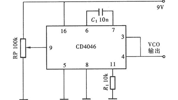 What is a Voltage Controlled Oscillator?
09 January 20269192
FTDI, Future Technology Devices International Ltd
In Stock: 11
United States
China
Canada
Japan
Russia
Germany
United Kingdom
Singapore
Italy
Hong Kong(China)
Taiwan(China)
France
Korea
Mexico
Netherlands
Malaysia
Austria
Spain
Switzerland
Poland
Thailand
Vietnam
India
United Arab Emirates
Afghanistan
Åland Islands
Albania
Algeria
American Samoa
Andorra
Angola
Anguilla
Antigua & Barbuda
Argentina
Armenia
Aruba
Australia
Azerbaijan
Bahamas
Bahrain
Bangladesh
Barbados
Belarus
Belgium
Belize
Benin
Bermuda
Bhutan
Bolivia
Bonaire, Sint Eustatius and Saba
Bosnia & Herzegovina
Botswana
Brazil
British Indian Ocean Territory
British Virgin Islands
Brunei
Bulgaria
Burkina Faso
Burundi
Cabo Verde
Cambodia
Cameroon
Cayman Islands
Central African Republic
Chad
Chile
Christmas Island
Cocos (Keeling) Islands
Colombia
Comoros
Congo
Congo (DRC)
Cook Islands
Costa Rica
Côte d’Ivoire
Croatia
Cuba
Curaçao
Cyprus
Czechia
Denmark
Djibouti
Dominica
Dominican Republic
Ecuador
Egypt
El Salvador
Equatorial Guinea
Eritrea
Estonia
Eswatini
Ethiopia
Falkland Islands
Faroe Islands
Fiji
Finland
French Guiana
French Polynesia
Gabon
Gambia
Georgia
Ghana
Gibraltar
Greece
Greenland
Grenada
Guadeloupe
Guam
Guatemala
Guernsey
Guinea
Guinea-Bissau
Guyana
Haiti
Honduras
Hungary
Iceland
Indonesia
Iran
Iraq
Ireland
Isle of Man
Israel
Jamaica
Jersey
Jordan
Kazakhstan
Kenya
Kiribati
Kosovo
Kuwait
Kyrgyzstan
Laos
Latvia
Lebanon
Lesotho
Liberia
Libya
Liechtenstein
Lithuania
Luxembourg
Macao(China)
Madagascar
Malawi
Maldives
Mali
Malta
Marshall Islands
Martinique
Mauritania
Mauritius
Mayotte
Micronesia
Moldova
Monaco
Mongolia
Montenegro
Montserrat
Morocco
Mozambique
Myanmar
Namibia
Nauru
Nepal
New Caledonia
New Zealand
Nicaragua
Niger
Nigeria
Niue
Norfolk Island
North Korea
North Macedonia
Northern Mariana Islands
Norway
Oman
Pakistan
Palau
Palestinian Authority
Panama
Papua New Guinea
Paraguay
Peru
Philippines
Pitcairn Islands
Portugal
Puerto Rico
Qatar
Réunion
Romania
Rwanda
Samoa
San Marino
São Tomé & Príncipe
Saudi Arabia
Senegal
Serbia
Seychelles
Sierra Leone
Sint Maarten
Slovakia
Slovenia
Solomon Islands
Somalia
South Africa
South Sudan
Sri Lanka
St Helena, Ascension, Tristan da Cunha
St. Barthélemy
St. Kitts & Nevis
St. Lucia
St. Martin
St. Pierre & Miquelon
St. Vincent & Grenadines
Sudan
Suriname
Svalbard & Jan Mayen
Sweden
Syria
Tajikistan
Tanzania
Timor-Leste
Togo
Tokelau
Tonga
Trinidad & Tobago
Tunisia
Turkey
Turkmenistan
Turks & Caicos Islands
Tuvalu
U.S. Outlying Islands
U.S. Virgin Islands
Uganda
Ukraine
Uruguay
Uzbekistan
Vanuatu
Vatican City
Venezuela
Wallis & Futuna
Yemen
Zambia
Zimbabwe
![FT232RQ-REEL]() FT232RQ-REEL
FT232RQ-REELFTDI, Future Technology Devices International Ltd
![FT4232HL-REEL]() FT4232HL-REEL
FT4232HL-REELFTDI, Future Technology Devices International Ltd
![FT230XQ-R]() FT230XQ-R
FT230XQ-RFTDI, Future Technology Devices International Ltd
![FT4232HQ-REEL]() FT4232HQ-REEL
FT4232HQ-REELFTDI, Future Technology Devices International Ltd
![FT230XS-R]() FT230XS-R
FT230XS-RFTDI, Future Technology Devices International Ltd
![FT245RL-REEL]() FT245RL-REEL
FT245RL-REELFTDI, Future Technology Devices International Ltd
![FT232BL-TRAY]() FT232BL-TRAY
FT232BL-TRAYFTDI, Future Technology Devices International Ltd
![FT231XQ-R]() FT231XQ-R
FT231XQ-RFTDI, Future Technology Devices International Ltd
![FT232RL-TUBE]() FT232RL-TUBE
FT232RL-TUBEFTDI, Future Technology Devices International Ltd


