
 Product
 Brand
Brand Articles
 Tools
Tools
How to Leverage STM32F405VGT6 Datasheet for Advanced Designs

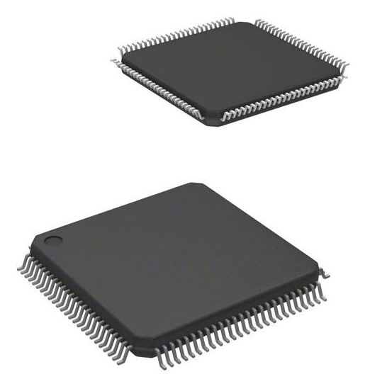
1MB 1M x 8 FLASH ARM® Cortex®-M4 32-Bit Microcontroller STM32F4 Series STM32F405 100 Pin 168MHz 3.3V 100-LQFP


1MB 1M x 8 FLASH ARM® Cortex®-M4 32-Bit Microcontroller STM32F4 Series STM32F405 100 Pin 168MHz 3.3V 100-LQFP
Master the STM32F405VGT6 datasheet to optimize hardware and software designs. Learn about pin configurations, electrical specs, and peripheral interfaces.
Product Introduction
The STM32F405VGT6 datasheet serves as a vital resource for your design projects. It provides detailed information about the STM32F405 microcontroller, helping you make informed decisions during development. By using this datasheet, you gain insights into pin configurations, electrical characteristics, and peripheral interfaces. These details ensure your hardware functions efficiently and your software interacts seamlessly with the microcontroller. Whether you are troubleshooting or optimizing performance, the datasheet equips you with the technical knowledge to achieve advanced results.
Understanding the STM32F405VGT6 Datasheet
Key Sections Overview
The STM32F405VGT6 datasheet contains essential details that guide you through your design process. Each section focuses on a specific aspect of the microcontroller, helping you understand its capabilities and limitations. Here's a quick overview of the key sections and their functionalities:
| Section | Functionality Description |
|---|---|
| Core Architecture | Arm 32-bit Cortex-M4 CPU with FPU, enabling high performance and DSP instructions. |
| Memory Specifications | Up to 1 Mbyte of flash memory and 192 Kbytes of SRAM, supporting various memory types and configurations. |
| Peripheral Interfaces | Includes ADCs, DACs, timers, and communication interfaces for diverse application needs. |
| Low-Power Operation | Features sleep, stop, and standby modes for energy efficiency in applications. |
| Debug Mode | Serial wire debug (SWD) & JTAG interfaces for development and debugging support. |
| Advanced Connectivity | USB 2.0 and Ethernet MAC for enhanced communication capabilities. |
| Unique Features | True random number generator and CRC calculation unit for security and data integrity. |
By understanding these sections, you can identify the features that align with your project requirements. For instance, the Cortex-M4 core supports advanced applications like digital signal processing, while the low-power modes optimize energy consumption in portable designs.
Efficient Navigation Tips
Navigating the STM32F405VGT6 datasheet efficiently can save you time during development. Start by familiarizing yourself with the table of contents. This section provides a roadmap to locate specific details quickly. Use bookmarks or search functions in your PDF viewer to jump to relevant sections, such as pin configurations or electrical specifications.
When working on hardware design, focus on sections like pin configurations and power supply circuits. For example, the datasheet explains how the STM32F405 uses an AMS1117-3.3 voltage regulator to convert 5V input to a stable 3.3V for the MCU. It also highlights the importance of capacitors in smoothing voltage fluctuations. These details ensure your design remains stable and reliable.
For software development, prioritize sections like memory specifications and debug interfaces. The datasheet outlines how the JTAG/SWD interface simplifies programming and debugging. This feature is invaluable when testing your firmware or troubleshooting issues.
By mastering these navigation techniques, you can streamline your workflow and make the most of the STM32F405VGT6 datasheet in your design projects.
Applying the STM32F405VGT6 Datasheet to Hardware Design
Pinout and Configuration
The pinout section of the STM32F405VGT6 datasheet is your starting point for hardware design. It provides a detailed map of the microcontroller's pins, showing their functions and configurations. Each pin can serve multiple purposes, such as GPIO, communication interfaces, or power supply connections. You must carefully study this section to ensure proper connections in your project.
To simplify your design process, follow these steps:
Identify the required peripherals for your application, such as UART, SPI, or I2C.
Refer to the pinout table to locate the pins associated with these peripherals.
Check the alternate functions of each pin to avoid conflicts between peripherals.
Use the recommended pull-up or pull-down resistors for unused pins to prevent floating states.
For example, if your design includes a USB interface, the datasheet specifies the pins for USB_DM and USB_DP. These pins must connect to the USB connector properly to enable communication. Additionally, the datasheet highlights the importance of decoupling capacitors near the power pins to stabilize the voltage supply.
Tip: Use development tools like STM32CubeMX to visualize pin configurations and avoid errors during the design phase.
Electrical Specifications
Understanding the electrical specifications is crucial for designing a stable and reliable system. The STM32F405VGT6 datasheet provides detailed information about voltage levels, current limits, and power consumption. These parameters help you select compatible components and design efficient power circuits.
Key electrical specifications include:
Operating Voltage: The STM32F405 operates within a range of 1.8V to 3.6V. Ensure your power supply stays within this range to avoid damaging the microcontroller.
Current Consumption: The datasheet lists typical and maximum current values for different operating modes, such as run, sleep, and standby. Use this data to design a power-efficient system.
I/O Voltage Levels: The input and output voltage thresholds determine the compatibility of the microcontroller with other components in your circuit.
Clock Frequency: The STM32F405 supports a maximum clock frequency of 168 MHz, which impacts the performance of your firmware.
For instance, if your design includes an RTC, the datasheet specifies the required external crystal oscillator parameters. This ensures accurate timekeeping in your application. Similarly, when using the Ethernet interface, you must follow the recommended power supply and grounding guidelines to minimize noise and interference.
Note: Always cross-check the electrical specifications with the reference manual to ensure compliance with design requirements.
Peripheral Interfaces
The STM32F405 microcontroller offers a wide range of peripherals to support diverse applications. These include communication interfaces, timers, ADCs, DACs, and more. The datasheet provides detailed descriptions of each peripheral, including their features, configurations, and limitations.
Here are some popular peripherals and their use cases:
Communication Interfaces: The STM32F405 supports UART, SPI, I2C, USB, and Ethernet. These interfaces enable data exchange between the microcontroller and external devices. For example, you can use UART for serial communication or Ethernet for advanced communication interfaces in IoT applications.
Timers: The microcontroller includes multiple timers for tasks like PWM generation, input capture, and time-based events. These timers are essential for motor control, signal processing, and other time-sensitive applications.
Analog Peripherals: The ADCs and DACs allow you to interface with analog sensors and actuators. The datasheet specifies the resolution, sampling rate, and input voltage range for these peripherals.
Debug Interfaces: The JTAG and SWD interfaces simplify firmware debugging and programming. These tools are invaluable for rapid prototyping and troubleshooting.
When designing your project, refer to the peripheral section of the datasheet to configure the required features. For example, if your application involves audio processing, the Cortex-M4 core with DSP instructions and the DAC peripheral can handle audio signals efficiently.
Tip: Use software tools like STM32CubeIDE to configure peripherals and generate initialization code for your firmware.
Leveraging the STM32F405VGT6 Datasheet for Software Development
Register Maps and Memory Details
The STM32F405VGT6 datasheet provides a comprehensive view of the register maps and memory architecture, which are critical for firmware development. You can use this information to understand how the microcontroller organizes its resources and interacts with peripherals. The datasheet outlines the memory layout, including flash memory, SRAM, and peripheral registers, making it easier to allocate resources efficiently.
The STM32F405 features up to 1 Mbyte of flash memory and 192 Kbytes of SRAM. Flash memory stores your firmware, while SRAM handles runtime data. The datasheet specifies the memory regions and their addresses, helping you map your code and data sections correctly. For instance, the Cortex-M4 core uses a Harvard architecture, which separates instruction and data buses. This design improves performance by allowing simultaneous access to instructions and data.
When working with register maps, the datasheet provides detailed descriptions of each register, including their bit fields and functions. For example, if you need to configure a GPIO pin, the datasheet explains how to set the corresponding bits in the GPIOx_MODER register. By understanding these details, you can write precise and efficient firmware.
Tip: Use tools like STM32CubeIDE to visualize memory usage and generate initialization code for registers. This approach reduces errors and accelerates development.
Clock Setup and Configuration
The clock system in the STM32F405 is highly flexible, allowing you to optimize performance and power consumption for your applications. The datasheet explains the clock tree structure, which includes multiple clock sources, dividers, and multiplexers. You can use this information to configure the system clock and peripheral clocks according to your project requirements.
The STM32F405 supports several clock sources, such as the high-speed external (HSE) oscillator, high-speed internal (HSI) oscillator, and the phase-locked loop (PLL). The datasheet provides the specifications for each source, including frequency ranges and stability requirements. For example, if your design includes an RTC, you can use the low-speed external (LSE) oscillator for accurate timekeeping.
To configure the clock system, follow these steps:
Select the primary clock source based on your application's needs.
Configure the PLL to generate the desired system clock frequency, up to 168 MHz.
Set the clock dividers for the AHB, APB1, and APB2 buses to balance performance and power consumption.
Enable the peripheral clocks for the modules you plan to use.
The datasheet also highlights the importance of clock stability and jitter. These factors affect the performance of time-sensitive peripherals, such as ADCs and timers. By carefully setting up the clock system, you can ensure reliable operation across all modules.
Note: Always verify your clock configuration using the RCC_CFGR register and other related registers. This step ensures that your settings align with the datasheet's recommendations.
Interrupts and Timers
Interrupts and timers are essential for real-time applications, and the STM32F405 excels in both areas. The datasheet provides detailed information about the interrupt controller and timer modules, enabling you to implement responsive and accurate firmware.
The STM32F405 includes up to 17 timers, with twelve 16-bit timers and two 32-bit timers. These timers operate at frequencies up to 168 MHz, making them suitable for high-speed applications. Each timer supports multiple functions, such as input capture, output compare, PWM generation, and pulse counting. The table below summarizes the key features of the timers:
| Feature | Description |
|---|---|
| Timers | Up to 17 timers: up to twelve 16-bit and two 32-bit timers up to 168 MHz. |
| Timer Functions | Each timer supports up to 4 IC/OC/PWM or pulse counter and quadrature input. |
To use a timer, you need to configure its registers, such as TIMx_CR1 for control settings and TIMx_CNT for the counter value. The datasheet explains each register's purpose and how to set its bits for specific functions. For example, if you want to generate a PWM signal, you can configure the TIMx_CCMR1 register to set the output compare mode.
Interrupts enhance the responsiveness of your firmware by allowing the microcontroller to react to events immediately. The STM32F405 uses the Nested Vectored Interrupt Controller (NVIC) to manage interrupts. The datasheet lists all available interrupt sources and their priorities, helping you design an efficient interrupt handling system.
Tip: Use the STM32CubeMX tool to configure timers and interrupts graphically. This tool generates the initialization code, saving you time and reducing errors.
Practical Design Tips Using the STM32F405 Datasheet
Cross-Referencing with Reference Manuals
The STM32F405VGT6 datasheet provides a wealth of information, but pairing it with the reference manual can elevate your design process. The datasheet focuses on high-level details, while the reference manual dives deeper into the microcontroller's (MCU) internal workings. Together, they form a complete guide for your project.
For example, the datasheet outlines the memory layout, including flash memory and SRAM. However, the reference manual explains how to configure memory protection units or access specific registers. When working with peripherals, the datasheet lists their features, but the reference manual provides step-by-step instructions for initialization.
To cross-reference effectively:
Start with the datasheet to identify the features you need.
Use the reference manual to understand the detailed implementation.
Keep both documents open while designing to avoid missing critical details.
Tip: Bookmark sections in both documents for quick access. Tools like PDF viewers with search functions can save time.
Avoiding Common Mistakes
Even experienced designers can make errors when working with the STM32F405. The datasheet helps you avoid these pitfalls by providing clear guidelines.
Here are some common mistakes and how to prevent them:
Incorrect Pin Configuration: Misconfiguring pins can lead to hardware failures. Always double-check the pinout table and ensure no conflicts between peripherals.
Ignoring Electrical Limits: Exceeding voltage or current limits can damage the MCU. Refer to the electrical specifications and design your power circuits accordingly.
Improper Clock Setup: An unstable clock can cause erratic behavior. Follow the datasheet's recommendations for clock sources and PLL settings.
Overlooking Peripheral Dependencies: Some peripherals rely on shared resources. For instance, timers may share clock sources. Plan your design to avoid resource conflicts.
Note: Use tools like STM32CubeMX to validate your configurations. These tools can highlight potential issues before you finalize your design.
By cross-referencing documents and avoiding common mistakes, you can create robust and efficient designs with the STM32F405.
The STM32F405VGT6 datasheet plays a critical role in your design projects. It provides the technical foundation you need to create efficient hardware and software solutions. By integrating this document into your workflow, you can streamline development and avoid costly mistakes. Use it to understand key features like the ARM Cortex-M4 core, peripheral interfaces, and electrical specifications.
To deepen your knowledge, explore additional resources such as application notes, reference manuals, and community forums. These tools complement the datasheet and help you tackle complex design challenges with confidence.
FAQ
1. Why should you use the STM32F405VGT6 datasheet for your project?
The datasheet provides critical details about the microcontroller's features, pin configurations, and electrical specifications. It helps you design hardware and software that work efficiently. By using it, you avoid errors and ensure your project meets performance requirements.
2. How do you find specific information in the datasheet quickly?
Use the table of contents or the search function in your PDF viewer. Bookmark frequently used sections like pinout diagrams or electrical specifications. This saves time and helps you locate the information you need without hassle.
3. What tools complement the STM32F405VGT6 datasheet?
Tools like STM32CubeMX and STM32CubeIDE complement the datasheet. They help you visualize pin configurations, generate initialization code, and debug your firmware. These tools simplify your workflow and reduce the chances of errors.
4. What is the difference between the datasheet and the reference manual?
The datasheet provides high-level details like pinouts, electrical limits, and peripheral features. The reference manual dives deeper into the microcontroller's internal workings, including register configurations and advanced settings. Use both for a complete understanding.
5. How can you avoid common mistakes when using the STM32F405VGT6?
Double-check pin configurations and electrical limits. Follow the datasheet's recommendations for clock setup and peripheral usage. Use tools like STM32CubeMX to validate your design. These steps help you avoid errors and create a reliable system.
Tip: Always cross-reference the datasheet with the reference manual for accurate implementation.
Specifications
- TypeParameter
- Lifecycle Status
Lifecycle Status refers to the current stage of an electronic component in its product life cycle, indicating whether it is active, obsolete, or transitioning between these states. An active status means the component is in production and available for purchase. An obsolete status indicates that the component is no longer being manufactured or supported, and manufacturers typically provide a limited time frame for support. Understanding the lifecycle status is crucial for design engineers to ensure continuity and reliability in their projects.
ACTIVE (Last Updated: 7 months ago) - Factory Lead Time12 Weeks
- Mount
In electronic components, the term "Mount" typically refers to the method or process of physically attaching or fixing a component onto a circuit board or other electronic device. This can involve soldering, adhesive bonding, or other techniques to secure the component in place. The mounting process is crucial for ensuring proper electrical connections and mechanical stability within the electronic system. Different components may have specific mounting requirements based on their size, shape, and function, and manufacturers provide guidelines for proper mounting procedures to ensure optimal performance and reliability of the electronic device.
Surface Mount - Mounting Type
The "Mounting Type" in electronic components refers to the method used to attach or connect a component to a circuit board or other substrate, such as through-hole, surface-mount, or panel mount.
Surface Mount - Package / Case
refers to the protective housing that encases an electronic component, providing mechanical support, electrical connections, and thermal management.
100-LQFP - Number of Pins100
- Data ConvertersA/D 16x12b; D/A 2x12b
- Number of I/Os82
- Watchdog TimersYes
- Operating Temperature
The operating temperature is the range of ambient temperature within which a power supply, or any other electrical equipment, operate in. This ranges from a minimum operating temperature, to a peak or maximum operating temperature, outside which, the power supply may fail.
-40°C~85°C TA - Packaging
Semiconductor package is a carrier / shell used to contain and cover one or more semiconductor components or integrated circuits. The material of the shell can be metal, plastic, glass or ceramic.
Tray - Series
In electronic components, the "Series" refers to a group of products that share similar characteristics, designs, or functionalities, often produced by the same manufacturer. These components within a series typically have common specifications but may vary in terms of voltage, power, or packaging to meet different application needs. The series name helps identify and differentiate between various product lines within a manufacturer's catalog.
STM32F4 - JESD-609 Code
The "JESD-609 Code" in electronic components refers to a standardized marking code that indicates the lead-free solder composition and finish of electronic components for compliance with environmental regulations.
e4 - Part Status
Parts can have many statuses as they progress through the configuration, analysis, review, and approval stages.
Active - Moisture Sensitivity Level (MSL)
Moisture Sensitivity Level (MSL) is a standardized rating that indicates the susceptibility of electronic components, particularly semiconductors, to moisture-induced damage during storage and the soldering process, defining the allowable exposure time to ambient conditions before they require special handling or baking to prevent failures
3 (168 Hours) - Number of Terminations100
- Terminal Finish
Terminal Finish refers to the surface treatment applied to the terminals or leads of electronic components to enhance their performance and longevity. It can improve solderability, corrosion resistance, and overall reliability of the connection in electronic assemblies. Common finishes include nickel, gold, and tin, each possessing distinct properties suitable for various applications. The choice of terminal finish can significantly impact the durability and effectiveness of electronic devices.
Nickel/Palladium/Gold (Ni/Pd/Au) - Terminal Position
In electronic components, the term "Terminal Position" refers to the physical location of the connection points on the component where external electrical connections can be made. These connection points, known as terminals, are typically used to attach wires, leads, or other components to the main body of the electronic component. The terminal position is important for ensuring proper connectivity and functionality of the component within a circuit. It is often specified in technical datasheets or component specifications to help designers and engineers understand how to properly integrate the component into their circuit designs.
QUAD - Terminal Form
Occurring at or forming the end of a series, succession, or the like; closing; concluding.
GULL WING - Supply Voltage
Supply voltage refers to the electrical potential difference provided to an electronic component or circuit. It is crucial for the proper operation of devices, as it powers their functions and determines performance characteristics. The supply voltage must be within specified limits to ensure reliability and prevent damage to components. Different electronic devices have specific supply voltage requirements, which can vary widely depending on their design and intended application.
3.3V - Terminal Pitch
The center distance from one pole to the next.
0.5mm - Frequency
In electronic components, the parameter "Frequency" refers to the rate at which a signal oscillates or cycles within a given period of time. It is typically measured in Hertz (Hz) and represents how many times a signal completes a full cycle in one second. Frequency is a crucial aspect in electronic components as it determines the behavior and performance of various devices such as oscillators, filters, and communication systems. Understanding the frequency characteristics of components is essential for designing and analyzing electronic circuits to ensure proper functionality and compatibility with other components in a system.
168MHz - Base Part Number
The "Base Part Number" (BPN) in electronic components serves a similar purpose to the "Base Product Number." It refers to the primary identifier for a component that captures the essential characteristics shared by a group of similar components. The BPN provides a fundamental way to reference a family or series of components without specifying all the variations and specific details.
STM32F405 - Pin Count
a count of all of the component leads (or pins)
100 - Interface
In electronic components, the term "Interface" refers to the point at which two different systems, devices, or components connect and interact with each other. It can involve physical connections such as ports, connectors, or cables, as well as communication protocols and standards that facilitate the exchange of data or signals between the connected entities. The interface serves as a bridge that enables seamless communication and interoperability between different parts of a system or between different systems altogether. Designing a reliable and efficient interface is crucial in ensuring proper functionality and performance of electronic components and systems.
CAN, EBI/EMI, I2C, I2S, IrDA, LIN, SPI, UART, USART, USB - Memory Size
The memory capacity is the amount of data a device can store at any given time in its memory.
1MB - Oscillator Type
Wien Bridge Oscillator; RC Phase Shift Oscillator; Hartley Oscillator; Voltage Controlled Oscillator; Colpitts Oscillator; Clapp Oscillators; Crystal Oscillators; Armstrong Oscillator.
Internal - RAM Size
RAM size refers to the amount of random access memory (RAM) available in an electronic component, such as a computer or smartphone. RAM is a type of volatile memory that stores data and instructions that are actively being used by the device's processor. The RAM size is typically measured in gigabytes (GB) and determines how much data the device can store and access quickly for processing. A larger RAM size allows for smoother multitasking, faster loading times, and better overall performance of the electronic component. It is an important factor to consider when choosing a device, especially for tasks that require a lot of memory, such as gaming, video editing, or running multiple applications simultaneously.
192K x 8 - Voltage - Supply (Vcc/Vdd)
Voltage - Supply (Vcc/Vdd) is a key parameter in electronic components that specifies the voltage level required for the proper operation of the device. It represents the power supply voltage that needs to be provided to the component for it to function correctly. This parameter is crucial as supplying the component with the correct voltage ensures that it operates within its specified limits and performance characteristics. It is typically expressed in volts (V) and is an essential consideration when designing and using electronic circuits to prevent damage and ensure reliable operation.
1.8V~3.6V - uPs/uCs/Peripheral ICs Type
The parameter "uPs/uCs/Peripheral ICs Type" refers to the classification of various integrated circuits used in electronic devices. It encompasses microprocessors (uPs), microcontrollers (uCs), and peripheral integrated circuits that provide additional functionalities. This classification helps in identifying the specific type of chip used for processing tasks, controlling hardware, or interfacing with other components in a system. Understanding this parameter is essential for selecting the appropriate electronic components for a given application.
MICROCONTROLLER, RISC - Core Processor
The term "Core Processor" typically refers to the central processing unit (CPU) of a computer or electronic device. It is the primary component responsible for executing instructions, performing calculations, and managing data within the system. The core processor is often considered the brain of the device, as it controls the overall operation and functionality. It is crucial for determining the speed and performance capabilities of the device, as well as its ability to handle various tasks and applications efficiently. In modern devices, core processors can have multiple cores, allowing for parallel processing and improved multitasking capabilities.
ARM® Cortex®-M4 - Peripherals
In the context of electronic components, "Peripherals" refer to devices or components that are connected to a main system or device to enhance its functionality or provide additional features. These peripherals can include input devices such as keyboards, mice, and touchscreens, as well as output devices like monitors, printers, and speakers. Other examples of peripherals include external storage devices, network adapters, and cameras. Essentially, peripherals are external devices that expand the capabilities of a main electronic system or device.
Brown-out Detect/Reset, DMA, I2S, LCD, POR, PWM, WDT - Program Memory Type
Program memory typically refers to flash memory when it is used to hold the program (instructions). Program memory may also refer to a hard drive or solid state drive (SSD). Contrast with data memory.
FLASH - Core Size
Core size in electronic components refers to the physical dimensions of the core material used in devices such as inductors and transformers. The core size directly impacts the performance characteristics of the component, including its inductance, saturation current, and frequency response. A larger core size typically allows for higher power handling capabilities and lower core losses, while a smaller core size may result in a more compact design but with limitations on power handling and efficiency. Designers must carefully select the core size based on the specific requirements of the application to achieve optimal performance and efficiency.
32-Bit - Program Memory Size
Program Memory Size refers to the amount of memory available in an electronic component, such as a microcontroller or microprocessor, that is used to store program instructions. This memory is non-volatile, meaning that the data stored in it is retained even when the power is turned off. The program memory size determines the maximum amount of code that can be stored and executed by the electronic component. It is an important parameter to consider when selecting a component for a specific application, as insufficient program memory size may limit the functionality or performance of the device.
1MB 1M x 8 - Connectivity
In electronic components, "Connectivity" refers to the ability of a component to establish and maintain connections with other components or devices within a circuit. It is a crucial parameter that determines how easily signals can be transmitted between different parts of a circuit. Connectivity can be influenced by factors such as the number of input and output ports, the type of connectors used, and the overall design of the component. Components with good connectivity are essential for ensuring reliable and efficient operation of electronic systems.
CANbus, EBI/EMI, I2C, IrDA, LINbus, SPI, UART/USART, USB OTG - Bit Size
In electronic components, "Bit Size" refers to the number of bits that can be processed or stored by a particular component. A bit is the smallest unit of data in computing and can have a value of either 0 or 1. The Bit Size parameter is commonly used to describe the capacity or performance of components such as microprocessors, memory modules, and data buses. A larger Bit Size generally indicates a higher processing capability or storage capacity, allowing for more complex operations and larger amounts of data to be handled efficiently. It is an important specification to consider when selecting electronic components for specific applications that require certain levels of performance and data processing capabilities.
32 - Has ADC
Has ADC refers to the presence of an Analog-to-Digital Converter (ADC) in an electronic component. An ADC is a crucial component in many electronic devices as it converts analog signals, such as voltage or current, into digital data that can be processed by a digital system. Having an ADC allows the electronic component to interface with analog signals and convert them into a format that can be manipulated and analyzed digitally. This parameter is important for applications where analog signals need to be converted into digital form for further processing or control.
YES - DMA Channels
DMA (Direct Memory Access) Channels are a feature found in electronic components such as microcontrollers, microprocessors, and peripheral devices. DMA Channels allow data to be transferred directly between peripherals and memory without involving the CPU, thereby reducing the burden on the CPU and improving overall system performance. Each DMA Channel is typically assigned to a specific peripheral device or memory region, enabling efficient data transfer operations. The number of DMA Channels available in a system determines the concurrent data transfer capabilities and can vary depending on the specific hardware design. Overall, DMA Channels play a crucial role in optimizing data transfer efficiency and system performance in electronic devices.
YES - Data Bus Width
The data bus width in electronic components refers to the number of bits that can be transferred simultaneously between the processor and memory. It determines the amount of data that can be processed and transferred in a single operation. A wider data bus allows for faster data transfer speeds and improved overall performance of the electronic device. Common data bus widths include 8-bit, 16-bit, 32-bit, and 64-bit, with higher numbers indicating a larger capacity for data transfer. The data bus width is an important specification to consider when evaluating the speed and efficiency of a computer system or other electronic device.
32b - PWM Channels
PWM Channels, or Pulse Width Modulation Channels, refer to the number of independent PWM outputs available in an electronic component, such as a microcontroller or a motor driver. PWM is a technique used to generate analog-like signals by varying the duty cycle of a square wave signal. Each PWM channel can control the output of a specific device or component by adjusting the pulse width of the signal. Having multiple PWM channels allows for precise control of multiple devices simultaneously, making it a valuable feature in applications such as motor control, LED dimming, and audio signal generation. The number of PWM channels available in a component determines the flexibility and complexity of the system it can control.
YES - Number of Timers/Counters14
- Core Architecture
In electronic components, the term "Core Architecture" refers to the fundamental design and structure of the component's internal circuitry. It encompasses the arrangement of key components, such as processors, memory units, and input/output interfaces, within the device. The core architecture plays a crucial role in determining the component's performance, power efficiency, and overall capabilities. Different core architectures are optimized for specific applications and requirements, such as high-speed processing, low power consumption, or specialized functions. Understanding the core architecture of electronic components is essential for engineers and designers to select the most suitable components for their projects.
ARM - CPU Family
CPU Family refers to a classification of microprocessors that share a common architecture and design traits. It signifies a group of processors that are typically produced by the same manufacturer and have similar functionality and features. The CPU Family can encompass various models that may differ in performance, power consumption, and specific capabilities but retain a unified core design, allowing for compatibility with software and hardware. This classification helps users and developers to understand the performance characteristics and upgrade pathways of different CPU models within the same family.
CORTEX-M4 - Number of UART Channels2
- Number of ADC Channels16
- Number of I2C Channels3
- Number of Ethernet Channels1
- Height1.45mm
- Length14.2mm
- Width14.2mm
- REACH SVHC
The parameter "REACH SVHC" in electronic components refers to the compliance with the Registration, Evaluation, Authorization, and Restriction of Chemicals (REACH) regulation regarding Substances of Very High Concern (SVHC). SVHCs are substances that may have serious effects on human health or the environment, and their use is regulated under REACH to ensure their safe handling and minimize their impact.Manufacturers of electronic components need to declare if their products contain any SVHCs above a certain threshold concentration and provide information on the safe use of these substances. This information allows customers to make informed decisions about the potential risks associated with using the components and take appropriate measures to mitigate any hazards.Ensuring compliance with REACH SVHC requirements is essential for electronics manufacturers to meet regulatory standards, protect human health and the environment, and maintain transparency in their supply chain. It also demonstrates a commitment to sustainability and responsible manufacturing practices in the electronics industry.
No SVHC - Radiation Hardening
Radiation hardening is the process of making electronic components and circuits resistant to damage or malfunction caused by high levels of ionizing radiation, especially for environments in outer space (especially beyond the low Earth orbit), around nuclear reactors and particle accelerators, or during nuclear accidents or nuclear warfare.
No - RoHS Status
RoHS means “Restriction of Certain Hazardous Substances” in the “Hazardous Substances Directive” in electrical and electronic equipment.
ROHS3 Compliant - Lead Free
Lead Free is a term used to describe electronic components that do not contain lead as part of their composition. Lead is a toxic material that can have harmful effects on human health and the environment, so the electronics industry has been moving towards lead-free components to reduce these risks. Lead-free components are typically made using alternative materials such as silver, copper, and tin. Manufacturers must comply with regulations such as the Restriction of Hazardous Substances (RoHS) directive to ensure that their products are lead-free and environmentally friendly.
Lead Free
Parts with Similar Specs
- ImagePart NumberManufacturerPackage / CaseNumber of PinsCore ArchitectureData Bus WidthNumber of I/OInterfaceMemory SizeSupply VoltageView Compare
![STM32F405VGT6]()
STM32F405VGT6
100-LQFP
100
ARM
32 b
82
CAN, EBI/EMI, I2C, I2S, IrDA, LIN, SPI, UART, USART, USB
1 MB
3.3 V
![STM32F407VGT6TR]()
100-LQFP
100
ARM
32 b
82
CAN, EBI/EMI, Ethernet, I2C, I2S, IrDA, LIN, SPI, UART, USART, USB
1 MB
3.3 V
![ATSAM4SD16CA-AU]()
100-LQFP
100
ARM
32 b
82
CAN, EBI/EMI, Ethernet, I2C, I2S, IrDA, LIN, SPI, UART, USART, USB
1 MB
3.3 V
![STM32F407VGT6]()
100-LQFP
100
ARM
32 b
82
CAN, EBI/EMI, Ethernet, I2C, I2S, IrDA, LIN, SPI, UART, USART, USB
1 MB
3.3 V
![STM32F407VGT7]()
100-LQFP
100
ARM
32 b
79
EBI/EMI, I2C, I2S, IrDA, SPI, UART, USART, USB
1 MB
1.2 V


Datasheet PDF
- Datasheets :
 Silicon Labs EFM32LG Microcontroller: Technical Overview
29 February 2024121
 TMC5160 vs. TMC2209: How to Differentiate?
18 April 202220417
 H6 vs H7 Battery: Which One Do You Like Better?
01 April 202248753
 LPC1768FBD100: Overview, Features, and Applications
12 December 2023909
 BSS138LT1G Power MOSFET: Pinout, Datasheet, and Applications
23 July 20212043
 How to use ATTINY85 Microcontroller?
08 April 20223478
 2SC5200 NPN Transistor: Pinout, Datasheet, and Circuit
02 September 202142031
 MPSA18 Low Noise Transistor: Datasheet pdf, Pinout and Substitute
15 November 20213488
 What is a Cell Phone Antenna?
21 July 202131634
 Introduction to MD8002A Audio Amplifier
27 March 20259007
 Power Management Integrated Circuit (PMIC) Guide
10 February 202213848
 Applications of Sensors on CNC Machine Tools
13 September 202119171
 What is Solenoid Valve? How to Choose a Solenoid Valve?
06 January 20223673
 50 World Famous Sensor Manufacturing Companies
31 October 2025894868
 NOR Flash: Working, Structure and Applications
18 November 202113674
 Always charge the battery to 100%? Stop it!
15 October 20214383
STMicroelectronics
In Stock: 5940
United States
China
Canada
Japan
Russia
Germany
United Kingdom
Singapore
Italy
Hong Kong(China)
Taiwan(China)
France
Korea
Mexico
Netherlands
Malaysia
Austria
Spain
Switzerland
Poland
Thailand
Vietnam
India
United Arab Emirates
Afghanistan
Åland Islands
Albania
Algeria
American Samoa
Andorra
Angola
Anguilla
Antigua & Barbuda
Argentina
Armenia
Aruba
Australia
Azerbaijan
Bahamas
Bahrain
Bangladesh
Barbados
Belarus
Belgium
Belize
Benin
Bermuda
Bhutan
Bolivia
Bonaire, Sint Eustatius and Saba
Bosnia & Herzegovina
Botswana
Brazil
British Indian Ocean Territory
British Virgin Islands
Brunei
Bulgaria
Burkina Faso
Burundi
Cabo Verde
Cambodia
Cameroon
Cayman Islands
Central African Republic
Chad
Chile
Christmas Island
Cocos (Keeling) Islands
Colombia
Comoros
Congo
Congo (DRC)
Cook Islands
Costa Rica
Côte d’Ivoire
Croatia
Cuba
Curaçao
Cyprus
Czechia
Denmark
Djibouti
Dominica
Dominican Republic
Ecuador
Egypt
El Salvador
Equatorial Guinea
Eritrea
Estonia
Eswatini
Ethiopia
Falkland Islands
Faroe Islands
Fiji
Finland
French Guiana
French Polynesia
Gabon
Gambia
Georgia
Ghana
Gibraltar
Greece
Greenland
Grenada
Guadeloupe
Guam
Guatemala
Guernsey
Guinea
Guinea-Bissau
Guyana
Haiti
Honduras
Hungary
Iceland
Indonesia
Iran
Iraq
Ireland
Isle of Man
Israel
Jamaica
Jersey
Jordan
Kazakhstan
Kenya
Kiribati
Kosovo
Kuwait
Kyrgyzstan
Laos
Latvia
Lebanon
Lesotho
Liberia
Libya
Liechtenstein
Lithuania
Luxembourg
Macao(China)
Madagascar
Malawi
Maldives
Mali
Malta
Marshall Islands
Martinique
Mauritania
Mauritius
Mayotte
Micronesia
Moldova
Monaco
Mongolia
Montenegro
Montserrat
Morocco
Mozambique
Myanmar
Namibia
Nauru
Nepal
New Caledonia
New Zealand
Nicaragua
Niger
Nigeria
Niue
Norfolk Island
North Korea
North Macedonia
Northern Mariana Islands
Norway
Oman
Pakistan
Palau
Palestinian Authority
Panama
Papua New Guinea
Paraguay
Peru
Philippines
Pitcairn Islands
Portugal
Puerto Rico
Qatar
Réunion
Romania
Rwanda
Samoa
San Marino
São Tomé & Príncipe
Saudi Arabia
Senegal
Serbia
Seychelles
Sierra Leone
Sint Maarten
Slovakia
Slovenia
Solomon Islands
Somalia
South Africa
South Sudan
Sri Lanka
St Helena, Ascension, Tristan da Cunha
St. Barthélemy
St. Kitts & Nevis
St. Lucia
St. Martin
St. Pierre & Miquelon
St. Vincent & Grenadines
Sudan
Suriname
Svalbard & Jan Mayen
Sweden
Syria
Tajikistan
Tanzania
Timor-Leste
Togo
Tokelau
Tonga
Trinidad & Tobago
Tunisia
Turkey
Turkmenistan
Turks & Caicos Islands
Tuvalu
U.S. Outlying Islands
U.S. Virgin Islands
Uganda
Ukraine
Uruguay
Uzbekistan
Vanuatu
Vatican City
Venezuela
Wallis & Futuna
Yemen
Zambia
Zimbabwe
![STM32F103RBT6]() STM32F103RBT6
STM32F103RBT6STMicroelectronics
![STM32F103ZET6]() STM32F103ZET6
STM32F103ZET6STMicroelectronics
![STM32H743IIT6]() STM32H743IIT6
STM32H743IIT6STMicroelectronics
![STM32F407VET6]() STM32F407VET6
STM32F407VET6STMicroelectronics
![STM32F405RGT6]() STM32F405RGT6
STM32F405RGT6STMicroelectronics
![STM32F030C8T6]() STM32F030C8T6
STM32F030C8T6STMicroelectronics
![STM32F100C8T6B]() STM32F100C8T6B
STM32F100C8T6BSTMicroelectronics
![STM32F103VBT6]() STM32F103VBT6
STM32F103VBT6STMicroelectronics
![STM8S003F3U6TR]() STM8S003F3U6TR
STM8S003F3U6TRSTMicroelectronics
![STM32F429ZIT6]() STM32F429ZIT6
STM32F429ZIT6STMicroelectronics


