

 Product
 Brand
Brand Articles
 Tools
Tools
PIC18F4520 Microcontroller: Features, Pinout, and Datasheet [Video&FAQ]

32KB 16K x 16 FLASH PIC 8-Bit Microcontroller PIC® 18F Series PIC18F4520 44 Pin 40MHz 44-TQFP


32KB 16K x 16 FLASH PIC 8-Bit Microcontroller PIC® 18F Series PIC18F4520 44 Pin 40MHz 44-TQFP
PIC18F4520 is a Microchip PIC microcontroller that is mostly utilized in automation and embedded systems. It is available in three packages: PDIP, QFN, and TQFP. The first is a 40-pin package (which is the most common), while the other two have a 44-pin interface. This article mainly introduces features, pinout, datasheet and other information about Microchip Technology PIC18F4520.
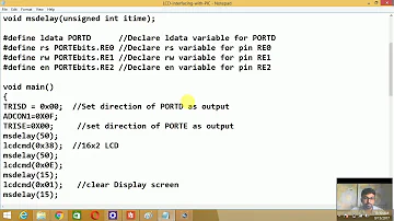
LCD interfacing with PIC18F4520
PIC18F4520 Description
PIC18F4520 is a Microchip PIC microcontroller that is mostly utilized in automation and embedded systems. It is available in three packages: PDIP , QFN , and TQFP . The first is a 40-pin package (which is the most common), while the other two have a 44-pin interface.
This microcontroller version has a CPU, timers, a 10-bit ADC, and other peripherals for developing connections with external devices. This PIC version, like others in the PIC community, includes everything needed to build an embedded system and automate processes.
The PIC18F4520 has 32K of program memory, 256 bytes of EEPROM data memory, 1536 bytes of RAM, and 256 bytes of EEPROM data memory, It also has two comparators, a 10-bit A/D converter with 13 channels, and decent memory endurance of roughly 1,000,000 for EEPROM and 100,000 for program memory, EUSART (Enhanced Universal Asynchronous Receiver Transmitter ) is a feature that can be used to develop serial connections with other devices.
The chip includes an asynchronous serial port that can be connected in either direction, using either the 3-wire Serial Peripheral Interface (SPI™) or the 2-wire Inter-Integrated Circuit (I²C™) Bus.
PIC18F4520 Pinout
The following figure is PIC18F4520 Pinout.

Pinout
| Pin Number | Pin Name | Description |
| 18 | MCLR/VPP/RE3 MCLR VPP RE3 | Master Clear (input) or programming voltage (input). Master Clear (Reset) input. This pin is an active-low Reset to the device. Programming voltage input. Digital input. |
| 30 | OSC1/CLKI/RA7 OSC1 CLKI RA7 | Oscillator crystal or external clock input. Oscillator crystal input or external clock source input. ST buffer when configured in RC mode; analog otherwise. External clock source input. Always associated with pin function, OSC1. (See related OSC1/CLKI, OSC2/CLKO pins.) General purpose I/O pin. |
| 31 | OSC2/CLKO/RA6 OSC2 CLKO RA6 | Oscillator crystal or clock output. Oscillator crystal output. Connects to crystal or resonator in Crystal Oscillator mode. In RC mode, OSC2 pin outputs CLKO which has 1/4 the frequency of OSC1 and denotes the instruction cycle rate. General purpose I/O pin. |
| PORTA is a bidirectional I/O port. | ||
| 19 | RA0/AN0 RA0 AN0 | Digital I/O. Analog input 0. |
| 20 | RA1/AN1 RA1 AN1 | Digital I/O. Analog input 1. |
| 21 | RA2/AN2/VREF-/CVREF RA2 AN2 VREF- CVREF | Digital I/O. Analog input 2. A/D reference voltage (low) input. Comparator reference voltage output. |
| 22 | RA3/AN3/VREF+ RA3 AN3 VREF+ | Digital I/O. Analog input 3. A/D reference voltage (high) input. |
| 23 | RA4/T0CKI/C1OUT RA4 T0CKI C1OUT | Digital I/O. Timer0 external clock input. Comparator 1 output. |
| 24 | RA5/AN4/SS/HLVDIN/C2OUT RA5 AN4 SS HLVDIN C2OUT | Digital I/O. Analog input 4. SPI slave select input. High/Low-Voltage Detect input. Comparator 2 output. |
| RA6 | See the OSC2/CLKO/RA6 pin. | |
| RA7 | See the OSC1/CLKI/RA7 pin. | |
| PORTB is a bidirectional I/O port. PORTB can be software programmed for internal weak pull-ups on all inputs. | ||
| 8 | RB0/INT0/FLT0/AN12 RB0 INT0 FLT0 AN12 | Digital I/O. External interrupt 0. PWM Fault input for Enhanced CCP1. Analog input 12. |
| 9 | RB1/INT1/AN10 RB1 INT1 AN10 | Digital I/O. External interrupt 1. Analog input 10. |
| 10 | RB2/INT2/AN8 RB2 INT2 AN8 | Digital I/O. External interrupt 2. Analog input 8. |
| 11 | RB3/AN9/CCP2 RB3 AN9 CCP2(1) | Digital I/O. Analog input 9. Capture 2 input/Compare 2 output/PWM2 output. |
| 14 | RB4/KBI0/AN11 RB4 KBI0 AN11 | Digital I/O. Interrupt-on-change pin. Analog input 11. |
| 15 | RB5/KBI1/PGM RB5 KBI1 PGM | Digital I/O. Interrupt-on-change pin. Low-Voltage ICSP™ Programming enable pin. |
| 16 | RB6/KBI2/PGC RB6 KBI2 PGC | Digital I/O. Interrupt-on-change pin. In-Circuit Debugger and ICSP programming clock pin. |
| 17 | RB7/KBI3/PGD RB7 KBI3 PGD | Digital I/O. Interrupt-on-change pin. In-Circuit Debugger and ICSP programming data pin. |
| PORTC is a bidirectional I/O port. | ||
| 32 | RC0/T1OSO/T13CKI RC0 T1OSO T13CKI | Digital I/O. Timer1 oscillator output. Timer1/Timer3 external clock input. |
| 35 | RC1/T1OSI/CCP2 RC1 T1OSI CCP2(2) | Digital I/O. Timer1 oscillator input. Capture 2 input/Compare 2 output/PWM2 output. |
| 36 | RC2/CCP1/P1A RC2 CCP1 P1A | Digital I/O. Capture 1 input/Compare 1 output/PWM1 output. Enhanced CCP1 output. |
| 37 | RC3/SCK/SCL RC3 SCK SCL | Digital I/O. Synchronous serial clock input/output for SPI mode. Synchronous serial clock input/output for I²C™ mode. |
| 42 | RC4/SDI/SDA RC4 SDI SDA | Digital I/O. SPI data in. I²C data I/O. |
| 43 | RC5/SDO RC5 SDO | Digital I/O. SPI data out. |
| 44 | RC6/TX/CK RC6 TX CK | Digital I/O. EUSART asynchronous transmit. EUSART synchronous clock (see related RX/DT). |
| 1 | RC7/RX/DT RC7 RX DT | Digital I/O. EUSART asynchronous receive. EUSART synchronous data (see related TX/CK). |
| PORTD is a bidirectional I/O port or a Parallel Slave Port (PSP) for interfacing to a microprocessor port. These pins have TTL input buffers when PSP module is enabled. | ||
| 38 | RD0/PSP0 RD0 PSP0 | Digital I/O. Parallel Slave Port data. |
| 39 | RD1/PSP1 RD1 PSP1 | Digital I/O. Parallel Slave Port data. |
| 40 | RD2/PSP2 RD2 PSP2 | Digital I/O. Parallel Slave Port data. |
| 41 | RD3/PSP3 RD3 PSP3 | Digital I/O. Parallel Slave Port data. |
| 2 | RD4/PSP4 RD4 PSP4 | Digital I/O. Parallel Slave Port data. |
| 3 | RD5/PSP5/P1B RD5 PSP5 P1B | Digital I/O. Parallel Slave Port data. Enhanced CCP1 output. |
| 4 | RD6/PSP6/P1C RD6 PSP6 P1C | Digital I/O. Parallel Slave Port data. Enhanced CCP1 output. |
| 5 | RD7/PSP7/P1D RD7 PSP7 P1D | Digital I/O. Parallel Slave Port data. Enhanced CCP1 output. |
| PORTE is a bidirectional I/O port. | ||
| 25 | RE0/RD/AN5 RE0 RD AN5 | Digital I/O. Read control for Parallel Slave Port (see also WR and CS pins). Analog input 5. |
| 26 | RE1/WR/AN6 RE1 WR AN6 | Digital I/O. Write control for Parallel Slave Port (see CS and RD pins). Analog input 6. |
| 27 | RE2/CS/AN7 RE2 CS AN7 | Digital I/O. Chip Select control for Parallel Slave Port (see related RD and WR). Analog input 7. |
| RE3 | See MCLR/VPP/RE3 pin. | |
| 6, 29 | VSS | Ground reference for logic and I/O pins. |
| 7, 28 | VDD | Positive supply for logic and I/O pins. |
| 12, 13, 33, 34 | NC | No Connect. |
PIC18F4520 CAD Model
The PIC18F4520 Symbol, Footprint and 3D Model are shown as follows.

Symbol
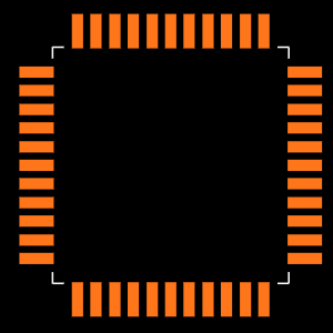
Footprint

3D Model
PIC18F4520 Features
(1) Power Management Features
• Run: CPU on, Peripherals on
• Idle: CPU off, Peripherals on
• Sleep: CPU off, Peripherals off
• Ultra Low 50nA Input Leakage
• Run mode Currents Down to 11 μA Typical
• Idle mode Currents Down to 2.5 μA Typical
• Sleep mode Current Down to 100 nA Typical
• Timer1 Oscillator: 900 nA, 32 kHz, 2V
• Watchdog Timer: 1.4 μA, 2V Typical
• Two-Speed Oscillator Start-up
(2) Flexible Oscillator Structure
• Four Crystal modes, up to 40 MHz
• 4x Phase Lock Loop (PLL) – Available for Crystal and Internal Oscillators
• Two External RC modes, up to 4 MHz
• Two External Clock modes, up to 40 MHz
• Internal Oscillator Block:
- Fast wake from Sleep and Idle, 1 μs typical
- 8 use-selectable frequencies, from 31 kHz to 8 MHz
- Provides a complete range of clock speeds from 31 kHz to 32 MHz when used with PLL
- User-tunable to compensate for frequency drift
• Secondary Oscillator using Timer1 @ 32 kHz
• Fail-Safe Clock Monitor:
- Allows for safe shutdown if peripheral clock stops
(3) Peripheral Highlights
• High-Current Sink/Source 25 mA/25 mA
• Three Programmable External Interrupts
• Four Input Change Interrupts
• Up to 2 Capture/Compare/PWM (CCP) modules, one with Auto-Shutdown (28-pin devices)
• Enhanced Capture/Compare/PWM (ECCP) module (40/44-pin devices only):
- One, two or four PWM outputs
- Selectable polarity
- Programmable dead time
- Auto-shutdown and auto-restart Peripheral Highlights (Continued):
• Master Synchronous Serial Port (MSSP) module Supporting 3-Wire SPI (all 4 modes) and I2C™ Master and Slave modes
• Enhanced Addressable USART module:
- Supports RS-485, RS-232 and LIN/J2602
- RS-232 operation using internal oscillator block (no external crystal required)
- Auto-wake-up on Start bit
- Auto-Baud Detect
• 10-Bit, up to 13-Channel Analog-to-Digital (A/D) Converter module:
- Auto-acquisition capability
- Conversion available during Sleep
• Dual Analog Comparators with Input Multiplexing
• Programmable 16-Level High/Low-Voltage Detection (HLVD) module:
- Supports interrupt on High/Low-Voltage Detection
(4) Special Microcontroller Features
• C Compiler Optimized Architecture
- Optional extended instruction set designed to optimize re-entrant code
• 100,000 Erase/Write Cycle Enhanced Flash Program Memory Typical
• 1,000,000 Erase/Write Cycle Data EEPROM Memory Typical
• Flash/Data EEPROM Retention: 100 Years Typical
• Self-Programmable under Software Control
• Priority Levels for Interrupts
• 8 x 8 Single-Cycle Hardware Multiplier
• Extended Watchdog Timer (WDT)
- Programmable period from 4 ms to 131s
• Single-Supply 5V In-Circuit Serial Programming™ (ICSP™) via Two Pins
• In-Circuit Debug (ICD) via Two Pins
• Wide Operating Voltage Range: 2.0V to 5.5V
• Programmable Brown-out Reset (BOR) with Software Enable Option
Specifications
- TypeParameter
- Factory Lead Time7 Weeks
- Mount
In electronic components, the term "Mount" typically refers to the method or process of physically attaching or fixing a component onto a circuit board or other electronic device. This can involve soldering, adhesive bonding, or other techniques to secure the component in place. The mounting process is crucial for ensuring proper electrical connections and mechanical stability within the electronic system. Different components may have specific mounting requirements based on their size, shape, and function, and manufacturers provide guidelines for proper mounting procedures to ensure optimal performance and reliability of the electronic device.
Surface Mount - Mounting Type
The "Mounting Type" in electronic components refers to the method used to attach or connect a component to a circuit board or other substrate, such as through-hole, surface-mount, or panel mount.
Surface Mount - Package / Case
refers to the protective housing that encases an electronic component, providing mechanical support, electrical connections, and thermal management.
44-TQFP - Number of Pins44
- Power Dissipation (Max)1W
- Current - Supply (Nom)1.1mA
- Number of I/Os36
- Data ConvertersA/D 13x10b
- Watchdog TimersYes
- Operating Temperature
The operating temperature is the range of ambient temperature within which a power supply, or any other electrical equipment, operate in. This ranges from a minimum operating temperature, to a peak or maximum operating temperature, outside which, the power supply may fail.
-40°C~85°C TA - Packaging
Semiconductor package is a carrier / shell used to contain and cover one or more semiconductor components or integrated circuits. The material of the shell can be metal, plastic, glass or ceramic.
Tray - Series
In electronic components, the "Series" refers to a group of products that share similar characteristics, designs, or functionalities, often produced by the same manufacturer. These components within a series typically have common specifications but may vary in terms of voltage, power, or packaging to meet different application needs. The series name helps identify and differentiate between various product lines within a manufacturer's catalog.
PIC® 18F - Published2016
- JESD-609 Code
The "JESD-609 Code" in electronic components refers to a standardized marking code that indicates the lead-free solder composition and finish of electronic components for compliance with environmental regulations.
e3 - Pbfree Code
The "Pbfree Code" parameter in electronic components refers to the code or marking used to indicate that the component is lead-free. Lead (Pb) is a toxic substance that has been widely used in electronic components for many years, but due to environmental concerns, there has been a shift towards lead-free alternatives. The Pbfree Code helps manufacturers and users easily identify components that do not contain lead, ensuring compliance with regulations and promoting environmentally friendly practices. It is important to pay attention to the Pbfree Code when selecting electronic components to ensure they meet the necessary requirements for lead-free applications.
yes - Part Status
Parts can have many statuses as they progress through the configuration, analysis, review, and approval stages.
Active - Moisture Sensitivity Level (MSL)
Moisture Sensitivity Level (MSL) is a standardized rating that indicates the susceptibility of electronic components, particularly semiconductors, to moisture-induced damage during storage and the soldering process, defining the allowable exposure time to ambient conditions before they require special handling or baking to prevent failures
3 (168 Hours) - Number of Terminations44
- Terminal Finish
Terminal Finish refers to the surface treatment applied to the terminals or leads of electronic components to enhance their performance and longevity. It can improve solderability, corrosion resistance, and overall reliability of the connection in electronic assemblies. Common finishes include nickel, gold, and tin, each possessing distinct properties suitable for various applications. The choice of terminal finish can significantly impact the durability and effectiveness of electronic devices.
Matte Tin (Sn) - Voltage - Supply
Voltage - Supply refers to the range of voltage levels that an electronic component or circuit is designed to operate with. It indicates the minimum and maximum supply voltage that can be applied for the device to function properly. Providing supply voltages outside this range can lead to malfunction, damage, or reduced performance. This parameter is critical for ensuring compatibility between different components in a circuit.
5V - Terminal Position
In electronic components, the term "Terminal Position" refers to the physical location of the connection points on the component where external electrical connections can be made. These connection points, known as terminals, are typically used to attach wires, leads, or other components to the main body of the electronic component. The terminal position is important for ensuring proper connectivity and functionality of the component within a circuit. It is often specified in technical datasheets or component specifications to help designers and engineers understand how to properly integrate the component into their circuit designs.
QUAD - Terminal Form
Occurring at or forming the end of a series, succession, or the like; closing; concluding.
GULL WING - Peak Reflow Temperature (Cel)
Peak Reflow Temperature (Cel) is a parameter that specifies the maximum temperature at which an electronic component can be exposed during the reflow soldering process. Reflow soldering is a common method used to attach electronic components to a circuit board. The Peak Reflow Temperature is crucial because it ensures that the component is not damaged or degraded during the soldering process. Exceeding the specified Peak Reflow Temperature can lead to issues such as component failure, reduced performance, or even permanent damage to the component. It is important for manufacturers and assemblers to adhere to the recommended Peak Reflow Temperature to ensure the reliability and functionality of the electronic components.
260 - Frequency
In electronic components, the parameter "Frequency" refers to the rate at which a signal oscillates or cycles within a given period of time. It is typically measured in Hertz (Hz) and represents how many times a signal completes a full cycle in one second. Frequency is a crucial aspect in electronic components as it determines the behavior and performance of various devices such as oscillators, filters, and communication systems. Understanding the frequency characteristics of components is essential for designing and analyzing electronic circuits to ensure proper functionality and compatibility with other components in a system.
40MHz - Time@Peak Reflow Temperature-Max (s)
Time@Peak Reflow Temperature-Max (s) refers to the maximum duration that an electronic component can be exposed to the peak reflow temperature during the soldering process, which is crucial for ensuring reliable solder joint formation without damaging the component.
40 - Base Part Number
The "Base Part Number" (BPN) in electronic components serves a similar purpose to the "Base Product Number." It refers to the primary identifier for a component that captures the essential characteristics shared by a group of similar components. The BPN provides a fundamental way to reference a family or series of components without specifying all the variations and specific details.
PIC18F4520 - Lead Pitch
Lead pitch in electronic components refers to the distance between the center of one lead (or pin) of a component to the center of the adjacent lead. It is an important parameter to consider when designing and assembling electronic circuits, as it determines the spacing required on a circuit board for proper placement and soldering of the component. Lead pitch is typically specified in millimeters or inches and can vary depending on the type of component, such as integrated circuits, resistors, capacitors, and connectors. Choosing the correct lead pitch ensures proper alignment and connection of components on a circuit board, ultimately affecting the functionality and reliability of the electronic device.
500μm - Power Supplies
an electronic circuit that converts the voltage of an alternating current (AC) into a direct current (DC) voltage.?
5V - Interface
In electronic components, the term "Interface" refers to the point at which two different systems, devices, or components connect and interact with each other. It can involve physical connections such as ports, connectors, or cables, as well as communication protocols and standards that facilitate the exchange of data or signals between the connected entities. The interface serves as a bridge that enables seamless communication and interoperability between different parts of a system or between different systems altogether. Designing a reliable and efficient interface is crucial in ensuring proper functionality and performance of electronic components and systems.
I2C, SPI, UART, USART - Memory Size
The memory capacity is the amount of data a device can store at any given time in its memory.
32kB - Oscillator Type
Wien Bridge Oscillator; RC Phase Shift Oscillator; Hartley Oscillator; Voltage Controlled Oscillator; Colpitts Oscillator; Clapp Oscillators; Crystal Oscillators; Armstrong Oscillator.
Internal - RAM Size
RAM size refers to the amount of random access memory (RAM) available in an electronic component, such as a computer or smartphone. RAM is a type of volatile memory that stores data and instructions that are actively being used by the device's processor. The RAM size is typically measured in gigabytes (GB) and determines how much data the device can store and access quickly for processing. A larger RAM size allows for smoother multitasking, faster loading times, and better overall performance of the electronic component. It is an important factor to consider when choosing a device, especially for tasks that require a lot of memory, such as gaming, video editing, or running multiple applications simultaneously.
1.5K x 8 - uPs/uCs/Peripheral ICs Type
The parameter "uPs/uCs/Peripheral ICs Type" refers to the classification of various integrated circuits used in electronic devices. It encompasses microprocessors (uPs), microcontrollers (uCs), and peripheral integrated circuits that provide additional functionalities. This classification helps in identifying the specific type of chip used for processing tasks, controlling hardware, or interfacing with other components in a system. Understanding this parameter is essential for selecting the appropriate electronic components for a given application.
MICROCONTROLLER, RISC - Number of Bits8
- Core Processor
The term "Core Processor" typically refers to the central processing unit (CPU) of a computer or electronic device. It is the primary component responsible for executing instructions, performing calculations, and managing data within the system. The core processor is often considered the brain of the device, as it controls the overall operation and functionality. It is crucial for determining the speed and performance capabilities of the device, as well as its ability to handle various tasks and applications efficiently. In modern devices, core processors can have multiple cores, allowing for parallel processing and improved multitasking capabilities.
PIC - Peripherals
In the context of electronic components, "Peripherals" refer to devices or components that are connected to a main system or device to enhance its functionality or provide additional features. These peripherals can include input devices such as keyboards, mice, and touchscreens, as well as output devices like monitors, printers, and speakers. Other examples of peripherals include external storage devices, network adapters, and cameras. Essentially, peripherals are external devices that expand the capabilities of a main electronic system or device.
Brown-out Detect/Reset, HLVD, POR, PWM, WDT - Program Memory Type
Program memory typically refers to flash memory when it is used to hold the program (instructions). Program memory may also refer to a hard drive or solid state drive (SSD). Contrast with data memory.
FLASH - Core Size
Core size in electronic components refers to the physical dimensions of the core material used in devices such as inductors and transformers. The core size directly impacts the performance characteristics of the component, including its inductance, saturation current, and frequency response. A larger core size typically allows for higher power handling capabilities and lower core losses, while a smaller core size may result in a more compact design but with limitations on power handling and efficiency. Designers must carefully select the core size based on the specific requirements of the application to achieve optimal performance and efficiency.
8-Bit - Program Memory Size
Program Memory Size refers to the amount of memory available in an electronic component, such as a microcontroller or microprocessor, that is used to store program instructions. This memory is non-volatile, meaning that the data stored in it is retained even when the power is turned off. The program memory size determines the maximum amount of code that can be stored and executed by the electronic component. It is an important parameter to consider when selecting a component for a specific application, as insufficient program memory size may limit the functionality or performance of the device.
32KB 16K x 16 - Connectivity
In electronic components, "Connectivity" refers to the ability of a component to establish and maintain connections with other components or devices within a circuit. It is a crucial parameter that determines how easily signals can be transmitted between different parts of a circuit. Connectivity can be influenced by factors such as the number of input and output ports, the type of connectors used, and the overall design of the component. Components with good connectivity are essential for ensuring reliable and efficient operation of electronic systems.
I2C, SPI, UART/USART - Bit Size
In electronic components, "Bit Size" refers to the number of bits that can be processed or stored by a particular component. A bit is the smallest unit of data in computing and can have a value of either 0 or 1. The Bit Size parameter is commonly used to describe the capacity or performance of components such as microprocessors, memory modules, and data buses. A larger Bit Size generally indicates a higher processing capability or storage capacity, allowing for more complex operations and larger amounts of data to be handled efficiently. It is an important specification to consider when selecting electronic components for specific applications that require certain levels of performance and data processing capabilities.
8 - Access Time
Access time in electronic components refers to the amount of time it takes for a system to retrieve data from memory or storage once a request has been made. It is typically measured in nanoseconds or microseconds and indicates the speed at which data can be accessed. Lower access time values signify faster performance, allowing for more efficient processing in computing systems. Access time is a critical parameter in determining the overall responsiveness of electronic devices, particularly in applications requiring quick data retrieval.
40 μs - Has ADC
Has ADC refers to the presence of an Analog-to-Digital Converter (ADC) in an electronic component. An ADC is a crucial component in many electronic devices as it converts analog signals, such as voltage or current, into digital data that can be processed by a digital system. Having an ADC allows the electronic component to interface with analog signals and convert them into a format that can be manipulated and analyzed digitally. This parameter is important for applications where analog signals need to be converted into digital form for further processing or control.
YES - DMA Channels
DMA (Direct Memory Access) Channels are a feature found in electronic components such as microcontrollers, microprocessors, and peripheral devices. DMA Channels allow data to be transferred directly between peripherals and memory without involving the CPU, thereby reducing the burden on the CPU and improving overall system performance. Each DMA Channel is typically assigned to a specific peripheral device or memory region, enabling efficient data transfer operations. The number of DMA Channels available in a system determines the concurrent data transfer capabilities and can vary depending on the specific hardware design. Overall, DMA Channels play a crucial role in optimizing data transfer efficiency and system performance in electronic devices.
NO - Data Rate
Data Rate is defined as the amount of data transmitted during a specified time period over a network. It is the speed at which data is transferred from one device to another or between a peripheral device and the computer. It is generally measured in Mega bits per second(Mbps) or Mega bytes per second(MBps).
10 Mbps - Data Bus Width
The data bus width in electronic components refers to the number of bits that can be transferred simultaneously between the processor and memory. It determines the amount of data that can be processed and transferred in a single operation. A wider data bus allows for faster data transfer speeds and improved overall performance of the electronic device. Common data bus widths include 8-bit, 16-bit, 32-bit, and 64-bit, with higher numbers indicating a larger capacity for data transfer. The data bus width is an important specification to consider when evaluating the speed and efficiency of a computer system or other electronic device.
8b - Number of Timers/Counters4
- Address Bus Width
A computer system has an address bus with 8 parallel lines. This means that the address bus width is 8 bits.
8b - Density
In electronic components, "Density" refers to the mass or weight of a material per unit volume. It is a physical property that indicates how tightly packed the atoms or molecules are within the material. The density of a component can affect its performance and characteristics, such as its strength, thermal conductivity, and electrical properties. Understanding the density of electronic components is important for designing and manufacturing processes to ensure optimal performance and reliability.
256 kb - EEPROM Size
EEPROM Size refers to the amount of memory capacity available in an Electrically Erasable Programmable Read-Only Memory (EEPROM) chip. This parameter indicates the total storage space in bytes or bits that can be used to store data in a non-volatile manner. The EEPROM size determines the maximum amount of information that can be written, read, and erased from the memory chip. It is an important specification to consider when selecting an EEPROM for a particular application, as it directly impacts the amount of data that can be stored and accessed by the electronic component.
256 x 8 - CPU Family
CPU Family refers to a classification of microprocessors that share a common architecture and design traits. It signifies a group of processors that are typically produced by the same manufacturer and have similar functionality and features. The CPU Family can encompass various models that may differ in performance, power consumption, and specific capabilities but retain a unified core design, allowing for compatibility with software and hardware. This classification helps users and developers to understand the performance characteristics and upgrade pathways of different CPU models within the same family.
PIC - Number of A/D Converters1
- Number of ADC Channels13
- Number of PWM Channels5
- Length10mm
- Height1.05mm
- Width10mm
- REACH SVHC
The parameter "REACH SVHC" in electronic components refers to the compliance with the Registration, Evaluation, Authorization, and Restriction of Chemicals (REACH) regulation regarding Substances of Very High Concern (SVHC). SVHCs are substances that may have serious effects on human health or the environment, and their use is regulated under REACH to ensure their safe handling and minimize their impact.Manufacturers of electronic components need to declare if their products contain any SVHCs above a certain threshold concentration and provide information on the safe use of these substances. This information allows customers to make informed decisions about the potential risks associated with using the components and take appropriate measures to mitigate any hazards.Ensuring compliance with REACH SVHC requirements is essential for electronics manufacturers to meet regulatory standards, protect human health and the environment, and maintain transparency in their supply chain. It also demonstrates a commitment to sustainability and responsible manufacturing practices in the electronics industry.
No SVHC - Radiation Hardening
Radiation hardening is the process of making electronic components and circuits resistant to damage or malfunction caused by high levels of ionizing radiation, especially for environments in outer space (especially beyond the low Earth orbit), around nuclear reactors and particle accelerators, or during nuclear accidents or nuclear warfare.
No - RoHS Status
RoHS means “Restriction of Certain Hazardous Substances” in the “Hazardous Substances Directive” in electrical and electronic equipment.
ROHS3 Compliant - Lead Free
Lead Free is a term used to describe electronic components that do not contain lead as part of their composition. Lead is a toxic material that can have harmful effects on human health and the environment, so the electronics industry has been moving towards lead-free components to reduce these risks. Lead-free components are typically made using alternative materials such as silver, copper, and tin. Manufacturers must comply with regulations such as the Restriction of Hazardous Substances (RoHS) directive to ensure that their products are lead-free and environmentally friendly.
Lead Free
Parts with Similar Specs
- ImagePart NumberManufacturerPackage / CaseNumber of PinsData Bus WidthNumber of I/OInterfaceMemory SizeSupply VoltagePeripheralsView Compare
![PIC18F4520-I/PT]()
PIC18F4520-I/PT
44-TQFP
44
8 b
36
I2C, SPI, UART, USART
32 kB
5 V
Brown-out Detect/Reset, HLVD, POR, PWM, WDT
![PIC18F4420-I/PT]()
44-TQFP
44
8 b
36
I2C, SPI, UART, USART
16 kB
5 V
Brown-out Detect/Reset, HLVD, POR, PWM, WDT
![PIC18F4321-I/PT]()
44-TQFP
44
8 b
36
I2C, SPI, UART, USART
16 kB
5 V
Brown-out Detect/Reset, HLVD, POR, PWM, WDT
![PIC18F4423-I/PT]()
44-TQFP
44
8 b
36
I2C, SPI, UART, USART
8 kB
5 V
Brown-out Detect/Reset, HLVD, POR, PWM, WDT

PIC18F4520 Functional Block Diagram


PIC18F4520 Alternatives
| Part Number | Description | Manufacturer |
| PIC18F4520T-E/MLMICROCONTROLLERS AND PROCESSORS | 8-BIT, FLASH, 40 MHz, RISC MICROCONTROLLER, PQCC44, 8 X 8 MM, PLASTIC, QFN-44 | Microchip Technology Inc |
| PIC18F4520-E/PTMICROCONTROLLERS AND PROCESSORS | 8-BIT, FLASH, 40 MHz, RISC MICROCONTROLLER, PQFP44, 10 X 10 MM, 1 MM HEIGHT, LEAD FREE, PLASTIC, TQFP-44 | Microchip Technology Inc |
PIC18F4520 Applications
• PIC18F4520 is widely used in home and industrial automation
• Student projects for motor controlling and sensor interfacing
• GPS and security systems
• Gas sensor projects
• Production of temperature data logger
• Serial Communication
• Central heating projects
• Embedded system
PIC18F4520 Package
The PIC18F4520 Package is shown as follows.

Package
PIC18F4520 Manufacturer
Microchip Technology Incorporated is a leading manufacturer of smart, networked, and secure embedded control solutions. Customers may create optimal designs using the company's simple development tools and broad product choices, which reduce risk while lowering overall system costs and time to market. The company's technologies are used by over 120,000 clients in the industrial, automotive, consumer, aerospace and defense, communications, and computing sectors. Microchip, based in Chandler, Arizona, offers outstanding technical support as well as dependable delivery and quality.
Trend Analysis
Datasheet PDF
- Datasheets :
- PCN Assembly/Origin :
- PCN Packaging :
- ConflictMineralStatement :
1.What is the difference between MCU PIC18F452 and PIC18F4520?
(1)The difference between the single-chip microcomputer PIC18F452 and PIC18F4520 is that one has a USB, the other does not.
(2) Microcontrollers are a kind of integrated circuit chip, which uses VLSI technology to integrate the central processing unit CPU with data processing capabilities, random access memory RAM, read-only memory ROM, various I/O ports and interrupt systems, timer/counter and other functions (may also include display drive circuit, pulse width modulation circuit, analog multiplexer, A/D converter and other circuits) are integrated on a silicon chip to form a small and complete microcomputer system, It is widely used in the field of industrial control. From the 1980s, from the then 4-bit and 8-bit single-chip microcomputers to the current 300M high-speed single-chip microcomputer.
2.How does the PIC18F4520 microcontroller adjust the PWM speed of the DC brushless motor?
The output PWM signal of the single-chip microcomputer can not be directly added to the switch tube, and the turn-on and the cut-off voltage value of the tube must be achieved through signal amplification. The single-chip microcomputer controls the switching tube to turn on and off after amplifying the PWM signal output by the program, thereby obtaining a large voltage and high current PWM signal formed by the switching tube. The sine signal can be simulated into sine wave signals of different frequencies to control the motor speed.
3.What is the difference between PIC18F4550 and PIC18F4520?
One with USB, the other does not.
 Eliminating Output Capacitors with XC6501 Series (Marking AB4): A High-Speed LDO Design Guide
10 February 2026249
 MAX3600A Laser Driver: Datasheet, Pinout, Circuit
31 August 2021437
 M10385 FM Module:Datasheet, Application, Schematic
01 September 2021911
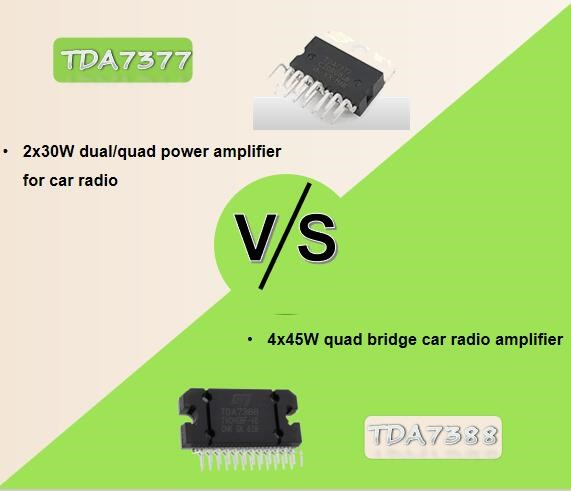 TDA7377 Amplifier vs TDA7388 Amplifier
05 November 202419054
 ADIS16477-2BMLZ Alternatives: Industrial Sensor Substitutes and Sourcing Guide
07 June 2025198
 STM32F103ZET6 Microcontroller: Specification, Pinout and Datasheet
20 October 20217247
 BSS138-7-F N-Chanel MOSFET: BSS138-7-F, Datasheet, Pinout
26 March 20222359
 SSM2164 VCA: Alternatives, Schematic, Datasheet
08 October 20215173
 Clock&Timing - Application Specific: A Dedicated Chip That Helps Produce Signals on the Circuit Board
22 February 20232277
 Use the Renesas AE-CLOUD2 to Send GPS Data to the Google Cloud IoT
15 November 20191446
 13 kinds of sensors in mobile phones and what are recorded by the sensors
10 June 2026131220
 How to Choose MOSFET for Switching Power Supply?
02 March 20229286
 Review of IoT-Based Smart Home Security Systems- Part 1
28 March 20244296
 How Electric Fuses Work: Types, Ratings, and Selection Guide
14 July 202618477
 Optimizations and applications of wide-band gap (wbg) semiconductor devices for ev systems
28 October 20223718
 What is a Transformer: Definition, Principle and Applications
03 November 20218712
Microchip Technology
In Stock: 60000
United States
China
Canada
Japan
Russia
Germany
United Kingdom
Singapore
Italy
Hong Kong(China)
Taiwan(China)
France
Korea
Mexico
Netherlands
Malaysia
Austria
Spain
Switzerland
Poland
Thailand
Vietnam
India
United Arab Emirates
Afghanistan
Åland Islands
Albania
Algeria
American Samoa
Andorra
Angola
Anguilla
Antigua & Barbuda
Argentina
Armenia
Aruba
Australia
Azerbaijan
Bahamas
Bahrain
Bangladesh
Barbados
Belarus
Belgium
Belize
Benin
Bermuda
Bhutan
Bolivia
Bonaire, Sint Eustatius and Saba
Bosnia & Herzegovina
Botswana
Brazil
British Indian Ocean Territory
British Virgin Islands
Brunei
Bulgaria
Burkina Faso
Burundi
Cabo Verde
Cambodia
Cameroon
Cayman Islands
Central African Republic
Chad
Chile
Christmas Island
Cocos (Keeling) Islands
Colombia
Comoros
Congo
Congo (DRC)
Cook Islands
Costa Rica
Côte d’Ivoire
Croatia
Cuba
Curaçao
Cyprus
Czechia
Denmark
Djibouti
Dominica
Dominican Republic
Ecuador
Egypt
El Salvador
Equatorial Guinea
Eritrea
Estonia
Eswatini
Ethiopia
Falkland Islands
Faroe Islands
Fiji
Finland
French Guiana
French Polynesia
Gabon
Gambia
Georgia
Ghana
Gibraltar
Greece
Greenland
Grenada
Guadeloupe
Guam
Guatemala
Guernsey
Guinea
Guinea-Bissau
Guyana
Haiti
Honduras
Hungary
Iceland
Indonesia
Iran
Iraq
Ireland
Isle of Man
Israel
Jamaica
Jersey
Jordan
Kazakhstan
Kenya
Kiribati
Kosovo
Kuwait
Kyrgyzstan
Laos
Latvia
Lebanon
Lesotho
Liberia
Libya
Liechtenstein
Lithuania
Luxembourg
Macao(China)
Madagascar
Malawi
Maldives
Mali
Malta
Marshall Islands
Martinique
Mauritania
Mauritius
Mayotte
Micronesia
Moldova
Monaco
Mongolia
Montenegro
Montserrat
Morocco
Mozambique
Myanmar
Namibia
Nauru
Nepal
New Caledonia
New Zealand
Nicaragua
Niger
Nigeria
Niue
Norfolk Island
North Korea
North Macedonia
Northern Mariana Islands
Norway
Oman
Pakistan
Palau
Palestinian Authority
Panama
Papua New Guinea
Paraguay
Peru
Philippines
Pitcairn Islands
Portugal
Puerto Rico
Qatar
Réunion
Romania
Rwanda
Samoa
San Marino
São Tomé & Príncipe
Saudi Arabia
Senegal
Serbia
Seychelles
Sierra Leone
Sint Maarten
Slovakia
Slovenia
Solomon Islands
Somalia
South Africa
South Sudan
Sri Lanka
St Helena, Ascension, Tristan da Cunha
St. Barthélemy
St. Kitts & Nevis
St. Lucia
St. Martin
St. Pierre & Miquelon
St. Vincent & Grenadines
Sudan
Suriname
Svalbard & Jan Mayen
Sweden
Syria
Tajikistan
Tanzania
Timor-Leste
Togo
Tokelau
Tonga
Trinidad & Tobago
Tunisia
Turkey
Turkmenistan
Turks & Caicos Islands
Tuvalu
U.S. Outlying Islands
U.S. Virgin Islands
Uganda
Ukraine
Uruguay
Uzbekistan
Vanuatu
Vatican City
Venezuela
Wallis & Futuna
Yemen
Zambia
Zimbabwe
![ATMEGA8515L-8AU]() ATMEGA8515L-8AU
ATMEGA8515L-8AUMicrochip Technology
![DSPIC30F6014A-30I/PF]() DSPIC30F6014A-30I/PF
DSPIC30F6014A-30I/PFMicrochip Technology
![ATMEGA32A-AU]() ATMEGA32A-AU
ATMEGA32A-AUMicrochip Technology
![ATXMEGA128A1U-AU]() ATXMEGA128A1U-AU
ATXMEGA128A1U-AUMicrochip Technology
![PIC18F46K20-I/PT]() PIC18F46K20-I/PT
PIC18F46K20-I/PTMicrochip Technology
![PIC18F6722-I/PT]() PIC18F6722-I/PT
PIC18F6722-I/PTMicrochip Technology
![PIC16F883-I/SS]() PIC16F883-I/SS
PIC16F883-I/SSMicrochip Technology
![PIC16F877-20I/PT]() PIC16F877-20I/PT
PIC16F877-20I/PTMicrochip Technology
![ATMEGA8535L-8AU]() ATMEGA8535L-8AU
ATMEGA8535L-8AUMicrochip Technology
![PIC18F4685-I/PT]() PIC18F4685-I/PT
PIC18F4685-I/PTMicrochip Technology


