
 Product
 Brand
Brand Articles
 Tools
Tools
How to Find the Ideal Voltage Reference for Your Application
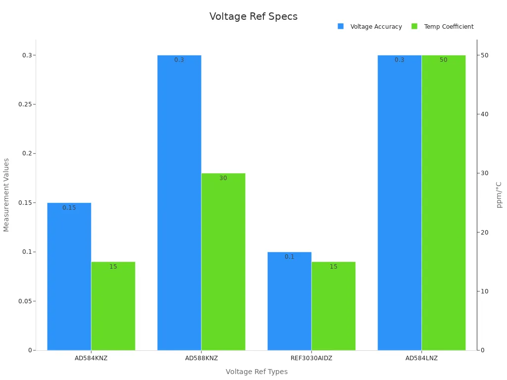
You need to match the voltage reference type and its key specifications—such as accuracy, stability, voltage, and current—to your project’s requirements. Small changes in voltage accuracy or temperature stability can make a big difference in your circuit’s performance. For example, a voltage reference with ±0.15% accuracy and ±15 ppm/°C temperature coefficient gives much better results than one with wider tolerances. The table below shows how different voltage reference choices affect important parameters:
| Parameter | AD584KNZ (High Precision) | AD588KNZ (Lower Precision) | REF3030AIDZ (Alternative) | AD584LNZ (Lower Stability) |
|---|---|---|---|---|
| Output Voltage | 10 V | 10 V | 3 V | 2.5 V |
| Voltage Accuracy | ±0.15% | ±0.3% | ±0.1% | ±0.3% |
| Temperature Coefficient | ±15 ppm/°C | ±30 ppm/°C | ±15 ppm/°C | ±50 ppm/°C |
| Max Output Current | 10 mA | 10 mA | 10 mA | 10 mA |
| Operating Current | 1 mA | N/A | N/A | N/A |
When choosing a reference, you ensure your design meets its goals for reliability and precision.
Voltage Reference Selection
Key Criteria
When you start voltage reference selection, you need to look at several important criteria. The most basic is the required output voltage. Your circuit may need a specific reference voltage, such as 2.5 V, 3 V, 5 V, or 10 V. You must also check the supply voltage range to make sure the voltage reference device works with your system’s power supply.
Load current is another key factor. Some applications need only a few microamps, while others require up to 20 mA or more. You should also pay close attention to accuracy and temperature stability. High performance voltage references offer better accuracy and lower temperature coefficients, which means less drift as the temperature changes.
Noise can affect sensitive circuits, especially in measurement or sensor applications. Lower noise voltage reference devices help you get more stable and precise results. Power consumption matters if you design for battery-powered or portable systems. Package size and type can affect both performance and how easily you can fit the device onto your PCB.
You should also consider features like power supply rejection ratio (PSRR), which shows how well the voltage reference blocks changes from the supply voltage. Fast startup time is important if your application needs quick power-up. Some voltage reference devices include built-in features, such as enable pins or output buffers, that can make your design easier.
Tip: Always match the voltage reference specifications to your project’s needs. This helps you avoid overdesign and keeps costs down.
Application Needs
Every application has its own set of requirements. You must match the voltage reference to your application requirements for the best performance. The table below shows the most critical technical specifications and their typical values:
| Parameter | Description | Typical Numerical Range / Units |
|---|---|---|
| Initial Accuracy | Output voltage error at 25°C | 0.02% to 5% (or in volts) |
| Temperature Coefficient | Change in output voltage per °C | 0.05 ppm/°C to ~150 ppm/°C |
| Long-Term Stability | Output voltage drift over 1000 hours or more | ppm per 1000 hours (e.g., 10 to 15 ppm) |
| Noise | Short-term voltage variation | μV peak-to-peak (0.1Hz–10Hz), μV RMS (10Hz–1kHz) |
| Load Current Handling | Maximum and optimal load current | Typically 10mA to 20mA max; external pass transistor can boost to ~100mA |
| Transient Response | Settling time and behavior under load steps | From 2μs (LT1027) to ~1ms (LT1009) |
You will find that voltage reference devices can vary a lot in accuracy and temperature coefficient. For example, a standard 7805 regulator gives about 4% accuracy, but a 1% accurate LM4040DIZ-5.0 shunt reference has a temperature coefficient of 150 ppm/°C. If you need even better performance, the LM4040AIZ-5.0 improves accuracy to 0.1% and has a 100 ppm/°C temperature coefficient. The Analog Devices AD586L offers 0.05% accuracy, a 5 ppm/°C temperature coefficient, and a 15 ppm/1000 hours aging rate. The Intersil X60008C achieves 0.01% accuracy, a 5 ppm/°C temperature coefficient, 10 ppm/1000 hours aging, and ultra-low supply current. These numbers show why you must focus on initial accuracy, temperature stability, and long-term drift when you select a voltage reference for your application.
Empirical data from real traction power supply systems show that choosing a voltage reference that matches your project’s specifications can greatly improve measurement performance. A three-step evaluation method uses voltage RMS data to detect deviations greater than 1% with high accuracy. Advanced models can estimate voltage outputs with errors less than ±0.5%. This approach helps you spot small measurement problems early, which prevents bigger faults and improves system reliability.
Environmental Factors
Environmental factors can change how your voltage reference performs over time. Temperature is one of the biggest influences. It affects long-term drift through the temperature coefficient and thermal hysteresis. The temperature coefficient measures how much the output voltage changes for each degree of temperature change. Thermal hysteresis shows the voltage difference after cycling the device through different temperatures.
Noise from the environment can add errors to your reference voltage, especially in high-precision applications. Humidity also plays a role. In plastic packages, moisture can cause the output voltage to drift more over time. Ceramic packages resist humidity better, so they show less drift.
Mechanical stress from the package size and material can affect long-term drift. For example, SOT-23 plastic packages and ceramic packages show different drift behaviors. Good PCB design helps reduce stress and improves measurement accuracy. Using PCB slotting and baking before testing can lower solder joint and thermal stress.
The table below summarizes how environmental factors impact voltage reference performance:
| Environmental Factor | Impact on Performance | Statistical/Experimental Evidence |
|---|---|---|
| Temperature | Affects long-term drift and thermal hysteresis | LTD measured in ppm over time; tempco and hysteresis plots |
| Noise | Adds system error, reduces precision | Evaluated with LTD and tempco |
| Humidity | Increases drift in plastic packages | LTD shifts with humidity changes |
| Package Stress | Changes drift over time | LTD plots for different packages |
| PCB Design | Reduces stress, improves accuracy | PCB slotting and baking methods |
| Long-Term Drift | Output voltage shift over thousands of hours | Automated bench testing |
You should always consider these environmental factors during voltage reference selection. By doing so, you ensure your voltage reference device delivers stable and reliable performance in your application.
Types of Voltage Reference

When you choose a voltage reference, you need to know the main types of voltage reference devices. Each type works best in different situations. The three most common types are series, shunt, and bandgap references.
Series Reference
A series voltage reference connects between your supply and the load. You do not need an external resistor. This type uses very little current, often just a few microamps to about 1 milliamp. You can turn off a series voltage reference to save power, which helps in battery-powered designs. For example, the MAX6025 and MAX6192 use only 35µA. Series references also have low dropout voltage, so they work well when your supply voltage is close to your reference voltage. You often find both fixed and adjustable output options. Some devices include features like shutdown pins or output buffers.
Tip: Use a series voltage reference when you need low power and high efficiency, especially in portable or mobile devices.
Shunt Reference
A shunt voltage reference works like a Zener diode. You connect it in parallel with your load and use an external resistor to set the current. Shunt references always draw current, even when the load is off. This means higher power use, usually from 1mA to 10mA. For example, the LM4040 needs at least 60µA but can draw up to 15mA. You must calculate the resistor value to keep the current in the right range. Shunt references work well when your supply voltage is much higher than your reference voltage, or when you need simple voltage regulation.
| Reference Type | Quiescent Current | External Resistor | Power Use | Example Device (Current) |
|---|---|---|---|---|
| Series | µA to ~1mA | No | Low | MAX6025 (35µA) |
| Shunt | 1mA to 10mA | Yes | High | LM4040 (60µA–15mA) |
Bandgap Reference
A bandgap reference uses a special circuit to create a stable reference voltage, usually around 1.2V. Many modern series and shunt references use bandgap technology. Bandgap references offer good temperature stability and low power use. For example, the LM4140 has a temperature coefficient as low as 3 ppm/°C, and the REF32XX series drifts only about 55 ppm over 1000 hours. You can find both fixed and adjustable versions. Some bandgap references include features like thermal shutdown or enable pins.
Note: Bandgap references give you a balance of accuracy, low drift, and efficiency. They work well in most precision circuits.
You should pick the type of voltage reference that matches your current, power, and accuracy needs. Always check if you need a fixed or adjustable reference voltage and look for built-in features that make your design easier.
Critical Specifications
Accuracy
You should always check the accuracy of a voltage reference first. Accuracy tells you how close the output voltage is to the value printed on the datasheet. High accuracy means your circuit will work as expected, with less error in measurements. For example, measurement data from a signal chain using ADA4523-1, AD4630, and ADR1001 show 24-hour accuracy and drift that match standard 3-phase meters. Linearity tests with an 8.5-digit DMM confirm errors within ±0.1 ppm after calibration. The table below compares accuracy and related parameters for popular voltage references:
| Device | Initial Accuracy | Temp. Coefficient | Noise (0.1–10 Hz) | Thermal Hysteresis |
|---|---|---|---|---|
| REF35 | ±0.05% | 10 ppm/°C | 2.5 µV P-P | 20 ppm |
| REF3333 | ±0.2% | 30 ppm/°C | 8 µV P-P | 50 ppm |
| REF3033 | ±0.2% | 50 ppm/°C | 12 µV P-P | 60 ppm |
You need to select a reference with the required accuracy for your application. This helps you keep the maximum total error within your system’s limits.
Temperature Coefficient
Temperature coefficient shows how much the output voltage changes as temperature changes. Lower values mean better stability. Most sensitive applications use voltage references with temperature coefficients below 40 ppm/°C. Some advanced devices reach as low as 5.6 ppm/°C. For example:
A 17.6-nW reference achieves 35.7 ppm/°C.
Some bandgap references reach 5.6 ppm/°C in modern CMOS technology.
You should always choose a reference with a low temperature coefficient to keep your circuit stable across different environments.
Noise
Noise in a voltage reference can cause random changes in output voltage. This affects the stability and accuracy of your measurements. Tests show that low-frequency noise (0.1 Hz to 10 Hz) can be below 1 µV peak-to-peak in the best devices. The table below lists common noise measurements:
| Noise Type | Typical Value | Impact on Performance |
|---|---|---|
| Thermal Noise | <1 µV P-P (0.1–10 Hz) | Affects precision |
| Flicker Noise | Device-dependent | Can dominate at low frequency |
| Popcorn Noise | Rare, device-specific | Sudden jumps in output |
You should pick a reference with low noise for high-precision circuits.
Long-Term Drift
Long-term drift measures how much the output voltage changes over months or years. Controlled studies show that after nine months, the maximum deviation from the aging model is less than 200 ppm. The chart below shows how drift changes over time:
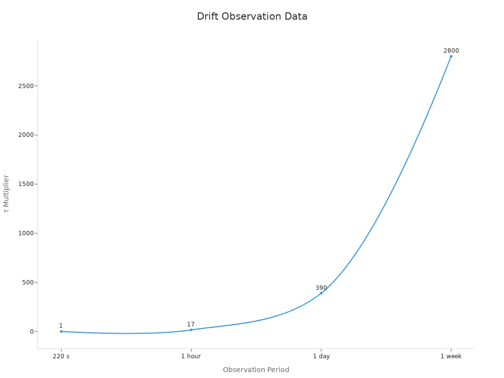
You want low drift to keep your system stable and reliable for years.
PSRR
Power Supply Rejection Ratio (PSRR) tells you how well the voltage reference blocks noise from the power supply. A high PSRR means less output voltage change when the supply voltage changes. Bandgap references often have higher PSRR and better temperature stability. You can improve PSRR by adding decoupling capacitors or using LDO regulators. Always check PSRR in the datasheet to compare voltage reference performance.
Thermal Hysteresis
Thermal hysteresis is the change in output voltage after the device cycles through different temperatures. Lower hysteresis means better stability. Devices like the REF35 show thermal hysteresis as low as 20 ppm. You should look for low thermal hysteresis if your circuit faces frequent temperature changes.
Tip: Always balance all critical specifications—accuracy, stability, noise, drift, PSRR, and thermal hysteresis—to get the best voltage reference performance for your project.
Selection Guide
Step-by-Step Process
You can simplify the process of choosing a reference by following a clear checklist. This approach helps you match your application needs to the right voltage reference features. Use the following points as your guide:
Check your supply voltage type. Use a shunt reference for very high supply voltages. Use a series reference if your supply voltage or load current changes often or if you need high power efficiency.
Identify the real-world temperature range for your application. Voltage references have guaranteed specifications over ranges like 0°C to 70°C, −40°C to 85°C, or −40°C to 125°C.
Combine all sources of error to estimate total accuracy. Include initial accuracy, temperature drift, thermal hysteresis, long-term drift, and noise.
Evaluate your supply voltage range, including possible fault conditions such as battery surges or spikes.
Match power consumption to your application. Some references use more than 1mA, while others use less than 1µA.
Determine load current needs. Decide if the reference must source or sink current, and check load regulation.
Consider package size and mounting method. Smaller packages may have tradeoffs, but mounting method often has a bigger impact on performance.
Review all key specifications: initial accuracy, temperature drift, long-term stability, thermal hysteresis, noise, line/load regulation, dropout voltage, supply range, and supply current.
Choose between series and shunt types based on your supply and load conditions.
Tip: Always use manufacturer datasheets to confirm that the voltage reference meets your application’s requirements.
You can also use a step-by-step method to ensure you select the best voltage reference for your project:
Calculate total accuracy by adding initial accuracy, temperature drift (using the box method for nonlinearities), long-term stability, and thermal hysteresis.
Review other important specifications such as load current, noise, line regulation, and load regulation.
Assess the impact of package type and mounting method on stability, since mechanical stress can affect performance.
Decide between series and shunt references based on your supply voltage and load current.
Calculate the maximum total error over your temperature range. Multiply temperature drift by the temperature range, then add initial accuracy, thermal hysteresis, and long-term drift.
For demanding applications, include noise, line regulation, and load regulation errors in your total accuracy calculation.
Check power consumption, maximum supply voltage, and whether the reference must source or sink current.
Use datasheets and distributor data to estimate output voltage error, especially for thermal hysteresis and long-term stability.
This process helps you make informed decisions and avoid common mistakes when selecting a voltage reference.
Examples
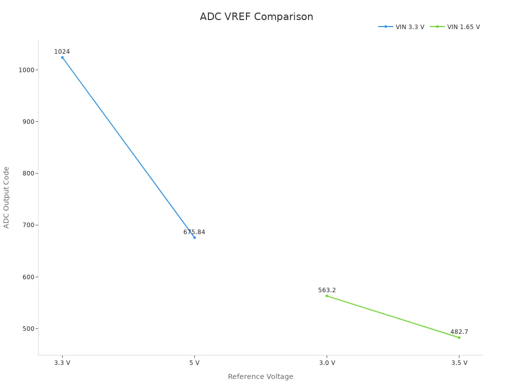
Let’s look at how these steps work in real-world applications. The table below shows how the choice of reference voltage affects the output code of a 10-bit ADC for different input voltages. This example highlights why high precision and stability matter in sensor and measurement circuits.
| Input Voltage (VIN) | Reference Voltage (VREF) | ADC Resolution (bits) | ADC Output Code Calculation | Resulting ADC Output Code |
|---|---|---|---|---|
| 3.3 V | 5 V | 10 | (VIN × 1024) / VREF | (3.3 × 1024) / 5 = 675.84 |
| 3.3 V | 3.3 V | 10 | (VIN × 1024) / VREF | (3.3 × 1024) / 3.3 = 1024 |
| 1.65 V | 3.5 V | 10 | (VIN × 1024) / VREF | (1.65 × 1024) / 3.5 = 482.7 |
| 1.65 V | 3.0 V | 10 | (VIN × 1024) / VREF | (1.65 × 1024) / 3.0 = 563.2 |
You can see that changing the reference voltage changes the ADC output code for the same input. This means that even small changes in reference voltage or its stability can affect your measurement results.
For example, if you use a reference with 0.2% maximum accuracy and 20 ppm/°C drift, your ADC readings will stay much more stable across temperature changes. This is important in sensor circuits, data acquisition, and any application where you need reliable and repeatable results.
Note: Always consider the total error budget, not just initial accuracy, when selecting a voltage reference for high precision designs.
By following this guide, you can confidently select a voltage reference that matches your application’s needs and ensures reliable circuit performance.
Application Scenarios
ADCs and DACs
You need a stable voltage reference device when you work with ADCs and DACs. High precision is important because even small changes in the reference voltage can cause big errors in digital output or input codes. For best results, choose a voltage reference with low temperature coefficient and low noise. This helps your measurements stay accurate over time.
Here is a table that shows how experts test and measure the performance of voltage references in these circuits:
| Aspect | Description |
|---|---|
| Experimental Setup | Use a high-speed, low-resolution ADC to oversample the sum of DAC output and a periodic reference voltage. Sinusoidal signals test static performance, while sawtooth signals test dynamic performance. |
| Signal Processing Method | Detect zero-crossing times to reconstruct the DAC output, even with non-uniform sampling. Spectral analysis helps check accuracy. |
| Performance Metrics | Accuracy, linearity, resolution, and ability to reconstruct signals from non-uniform data. |
| Advantages | Makes testing easier and faster. Keeps computational needs low. |
| Validation | MATLAB and lab tests confirm accuracy and effectiveness. |
| Key Outcome | Better accuracy in DAC tests and less test time compared to old methods. |
Tip: Always use a voltage reference with low drift and low noise for ADCs and DACs. This keeps your digital signals reliable.
Sensor Circuits
Sensor circuits often need a voltage reference that stays stable even when the temperature changes. Many sensors, like temperature or pressure sensors, give small signals. If your reference voltage drifts, your sensor readings will not be correct. Choose a voltage reference with a low temperature coefficient and low long-term drift. Series voltage reference types work well here because they use little power and provide steady output. You can also look for devices with built-in noise filtering to help your sensor circuit stay accurate.
Power Supplies
Power supplies need a voltage reference that gives a steady output voltage with low ripple. This helps your whole system stay precise and reliable. When you pick a voltage reference for power supplies, look at the output voltage range, current capacity, tolerance, temperature coefficient, and noise level. Series voltage reference types are good for most power supplies because they offer stable output and handle changes in load well. In some cases, you may want to use a floating-gate-array reference. These have much lower noise and better temperature stability than bandgap types, but they can be sensitive to X-rays and may not work with higher supply voltages.
Note: A voltage reference gives a fixed, precise voltage for measurement or control. A voltage regulator, on the other hand, supplies power and keeps the voltage steady even when the load changes. Use a voltage reference when you need accuracy, not just power.
Choosing the right voltage reference for your project matters. You must align the type and specifications with your circuit’s needs to achieve the best results. The table below shows how top models compare on key specs:
| Model | Temp. Coefficient (ppm/°C) | Initial Accuracy (%) | Output Voltage (V) | Long-Term Drift (ppm) |
|---|---|---|---|---|
| LT1031 | 5 | 0.05 | 10 | 15 per kHr |
| LT1019 | 5 | 0.05 | 2.5, 4.5, 5, 10 | 2.5 |
| LT1027 | 5 | 0.05 | 5 | 20 per month |
Careful selection improves accuracy, stability, and long-term performance.
You reduce errors from temperature drift, noise, and aging.
Your circuit stays reliable for years.
Use the steps in this guide to pick the best voltage reference for your next design. 🛠️
FAQ
What is the main difference between a voltage reference and a voltage regulator?
A voltage reference gives you a fixed, precise voltage for measurement or control. A voltage regulator supplies power and keeps the voltage steady for your circuit, even when the load changes.
How do I choose the right voltage reference for my ADC?
You should pick a voltage reference with high accuracy and low temperature drift. This helps your ADC give stable and correct readings. Check the datasheet for initial accuracy and temperature coefficient.
Can I use a shunt reference in low-power designs?
You should avoid shunt references in low-power designs. Shunt types always draw current, even with no load. Series references use less power and work better for battery-powered circuits.
Why does temperature coefficient matter?
Temperature coefficient shows how much the output voltage changes when temperature changes. A low temperature coefficient keeps your circuit stable in hot or cold conditions.
What package type should I select for best stability?
Ceramic packages give you better stability and less drift from humidity. Plastic packages cost less but can show more drift over time. Choose ceramic if you need high precision.
 UTMEL
UTMEL
We are the professional distributor of electronic components, providing a large variety of products to save you a lot of time, effort, and cost with our efficient self-customized service. careful order preparation fast delivery service
 Improving the Energy Conversion Efficiency of Triboelectric NanogeneratorsSaumitra Jagdale19 November 20242577
There is a huge growth in demand for self-sustaining electronic devices, as the traditional power-generating devices fail in remote and harsh environments due to the periodic requirement of battery changes. Also, these devices are frequency specific; some work only in high frequency and some in low frequency. Triboelectric nanogenerators (TENGs) provide a promising solution by efficiently converting mechanical energy into electricity as they are versatile, compact, and cheap, making them a popular choice.
Read More Methodologies for Increasing Efficiency of Fuel Stack Technology for Energy GenerationSaumitra Jagdale19 November 20242597
Presently, power companies are moving towards renewable energy systems. Conventional energy sources are more expensive because they require a vast network to be maintained and huge human resources. Also, they harm the environment by releasing several harmful gases. As the industry’s focus shifts toward renewable energy sources, energy systems powered by Proton Exchange Membrane Fuel Stacks (PEMFS) are gaining traction.
Read More Reconfigurable Antennas: Improving Efficiency in Modern CommunicationRakesh Kumar, Ph.D.24 December 20242523
This article highlights the limitations of conventional antennas and discusses the advantages of reconfigurable antenna designs. It also explores various reconfiguration techniques, applications, and their potential to enhance efficiency.
Read More The Ultimate Guide to AI Noise Reduction Translation EarbudsUTMEL01 April 20256790
In today’s connected world, talking to others is very important. You’ve likely seen how global business, travel, and learning need easy chats in different languages. This need keeps growing because of new tech like 5G and edge computing. These make fast and smooth connections possible.
Read More Comparing Popular Jumper Wires for Electronics ProjectsUTMEL10 July 20251651
Compare top jumper wires for electronics projects in 2025. Explore options by material, length, gauge, and durability to find the best fit for your needs.
Read More
Subscribe to Utmel !
![5906A]() 5906A
5906APomona Electronics
![1212370]() 1212370
1212370Phoenix Contact
![0011404418]() 0011404418
0011404418Molex
![36298]() 36298
36298Wiha
![HR30-7P-12SC-T01]() HR30-7P-12SC-T01
HR30-7P-12SC-T01Hirose Electric Co Ltd
![1212252]() 1212252
1212252Phoenix Contact
![0011185465]() 0011185465
0011185465Molex
![09990000844]() 09990000844
09990000844HARTING
![09990000341]() 09990000341
09990000341HARTING
![H-805R-UV]()


