
 Product
 Brand
Brand Articles
 Tools
Tools
74HC373 Octal D-type Transparent Latch: Datasheet pdf, Schematics and Pinout

Toshiba Semiconductor and Storage
2V~6V 8 Bits Tri-State Latches 74HC Series DUAL 20-SOIC (0.295, 7.50mm Width)
Unit Price: $0.403303
Ext Price: $0.40


2V~6V 8 Bits Tri-State Latches 74HC Series DUAL 20-SOIC (0.295, 7.50mm Width)
74HC373 is an Octal D-Type Latch with 3-State Outputs. This article is going to explain datasheet pdf, pinout, equivalents, schematics, and other details about the 74HC373 transparent latch.

74LS373 LATCH CHIP || Microprocessor
What is 74HC373?
The 74HC373 is a high-speed CMOS OCTAL LATCH with 3-STATE OUTPUT fabricated with silicon gate C2MOS technology. It achieves high-speed operation comparable to LSTTL while keeping CMOS low power dissipation.
A latch enables input (LE) and output enables input (OE) to control these 8-bit D-type latch es (OE). The eight outputs have a high impedance state when the OE input is high. Static discharge and transient excess voltage safety circuits are installed on all inputs.

74HC373 Logic Symbol
74HC373 Pinout

74HC373 Pinout
74HC373 CAD Model

74HC373 Symbol

74HC373 Footpirnt
Specifications
- TypeParameter
- Factory Lead Time12 Weeks
- Mounting Type
The "Mounting Type" in electronic components refers to the method used to attach or connect a component to a circuit board or other substrate, such as through-hole, surface-mount, or panel mount.
Surface Mount - Package / Case
refers to the protective housing that encases an electronic component, providing mechanical support, electrical connections, and thermal management.
20-SOIC (0.295, 7.50mm Width) - Surface Mount
having leads that are designed to be soldered on the side of a circuit board that the body of the component is mounted on.
YES - Operating Temperature
The operating temperature is the range of ambient temperature within which a power supply, or any other electrical equipment, operate in. This ranges from a minimum operating temperature, to a peak or maximum operating temperature, outside which, the power supply may fail.
-40°C~125°C - Packaging
Semiconductor package is a carrier / shell used to contain and cover one or more semiconductor components or integrated circuits. The material of the shell can be metal, plastic, glass or ceramic.
Cut Tape (CT) - Series
In electronic components, the "Series" refers to a group of products that share similar characteristics, designs, or functionalities, often produced by the same manufacturer. These components within a series typically have common specifications but may vary in terms of voltage, power, or packaging to meet different application needs. The series name helps identify and differentiate between various product lines within a manufacturer's catalog.
74HC - Published2016
- Part Status
Parts can have many statuses as they progress through the configuration, analysis, review, and approval stages.
Active - Moisture Sensitivity Level (MSL)
Moisture Sensitivity Level (MSL) is a standardized rating that indicates the susceptibility of electronic components, particularly semiconductors, to moisture-induced damage during storage and the soldering process, defining the allowable exposure time to ambient conditions before they require special handling or baking to prevent failures
1 (Unlimited) - Number of Terminations20
- Voltage - Supply
Voltage - Supply refers to the range of voltage levels that an electronic component or circuit is designed to operate with. It indicates the minimum and maximum supply voltage that can be applied for the device to function properly. Providing supply voltages outside this range can lead to malfunction, damage, or reduced performance. This parameter is critical for ensuring compatibility between different components in a circuit.
2V~6V - Terminal Position
In electronic components, the term "Terminal Position" refers to the physical location of the connection points on the component where external electrical connections can be made. These connection points, known as terminals, are typically used to attach wires, leads, or other components to the main body of the electronic component. The terminal position is important for ensuring proper connectivity and functionality of the component within a circuit. It is often specified in technical datasheets or component specifications to help designers and engineers understand how to properly integrate the component into their circuit designs.
DUAL - Terminal Form
Occurring at or forming the end of a series, succession, or the like; closing; concluding.
GULL WING - Peak Reflow Temperature (Cel)
Peak Reflow Temperature (Cel) is a parameter that specifies the maximum temperature at which an electronic component can be exposed during the reflow soldering process. Reflow soldering is a common method used to attach electronic components to a circuit board. The Peak Reflow Temperature is crucial because it ensures that the component is not damaged or degraded during the soldering process. Exceeding the specified Peak Reflow Temperature can lead to issues such as component failure, reduced performance, or even permanent damage to the component. It is important for manufacturers and assemblers to adhere to the recommended Peak Reflow Temperature to ensure the reliability and functionality of the electronic components.
NOT SPECIFIED - Number of Functions1
- Supply Voltage
Supply voltage refers to the electrical potential difference provided to an electronic component or circuit. It is crucial for the proper operation of devices, as it powers their functions and determines performance characteristics. The supply voltage must be within specified limits to ensure reliability and prevent damage to components. Different electronic devices have specific supply voltage requirements, which can vary widely depending on their design and intended application.
4.5V - Time@Peak Reflow Temperature-Max (s)
Time@Peak Reflow Temperature-Max (s) refers to the maximum duration that an electronic component can be exposed to the peak reflow temperature during the soldering process, which is crucial for ensuring reliable solder joint formation without damaging the component.
NOT SPECIFIED - JESD-30 Code
JESD-30 Code refers to a standardized descriptive designation system established by JEDEC for semiconductor-device packages. This system provides a systematic method for generating designators that convey essential information about the package's physical characteristics, such as size and shape, which aids in component identification and selection. By using JESD-30 codes, manufacturers and engineers can ensure consistency and clarity in the specification of semiconductor packages across various applications and industries.
R-PDSO-G20 - Output Type
The "Output Type" parameter in electronic components refers to the type of signal or data that is produced by the component as an output. This parameter specifies the nature of the output signal, such as analog or digital, and can also include details about the voltage levels, current levels, frequency, and other characteristics of the output signal. Understanding the output type of a component is crucial for ensuring compatibility with other components in a circuit or system, as well as for determining how the output signal can be utilized or processed further. In summary, the output type parameter provides essential information about the nature of the signal that is generated by the electronic component as its output.
Tri-State - Circuit
The parameter "Circuit" in electronic components refers to the interconnected arrangement of various electronic elements such as resistors, capacitors, inductors, and active devices like transistors. It defines the path through which electric current flows and establishes the operational behavior of the components within that system. Circuits can be classified as analog or digital, depending on the type of signals they handle, and can vary in complexity from simple series or parallel configurations to intricate designs used in advanced applications.
8:8 - Supply Voltage-Max (Vsup)
The parameter "Supply Voltage-Max (Vsup)" in electronic components refers to the maximum voltage that can be safely applied to the component without causing damage. It is an important specification to consider when designing or using electronic circuits to ensure the component operates within its safe operating limits. Exceeding the maximum supply voltage can lead to overheating, component failure, or even permanent damage. It is crucial to adhere to the specified maximum supply voltage to ensure the reliable and safe operation of the electronic component.
6V - Supply Voltage-Min (Vsup)
The parameter "Supply Voltage-Min (Vsup)" in electronic components refers to the minimum voltage level required for the component to operate within its specified performance range. This parameter indicates the lowest voltage that can be safely applied to the component without risking damage or malfunction. It is crucial to ensure that the supply voltage provided to the component meets or exceeds this minimum value to ensure proper functionality and reliability. Failure to adhere to the specified minimum supply voltage may result in erratic behavior, reduced performance, or even permanent damage to the component.
2V - Number of Ports
A port is identified for each transport protocol and address combination by a 16-bit unsigned number,.
2 - Number of Bits8
- Family
In electronic components, the parameter "Family" typically refers to a categorization or classification system used to group similar components together based on their characteristics, functions, or applications. This classification helps users easily identify and select components that meet their specific requirements. The "Family" parameter can include various subcategories such as resistors, capacitors, diodes, transistors, integrated circuits, and more. Understanding the "Family" of an electronic component can provide valuable information about its compatibility, performance specifications, and potential uses within a circuit or system. It is important to consider the "Family" parameter when designing or troubleshooting electronic circuits to ensure proper functionality and compatibility with other components.
HC/UH - Output Characteristics
Output characteristics in electronic components refer to the relationship between the output voltage and output current across a range of input conditions. This parameter is essential for understanding how a device, such as a transistor or operational amplifier, behaves under various loads and operating points. It provides insights into the efficiency, performance, and limitations of the component, helping designers to make informed choices for circuits and applications.
3-STATE - Logic Type
Logic Type in electronic components refers to the classification of circuits based on the logical operations they perform. It includes types such as AND, OR, NOT, NAND, NOR, XOR, and XNOR, each defining the relationship between binary inputs and outputs. The logic type determines how the inputs affect the output state based on specific rules of Boolean algebra. This classification is crucial for designing digital circuits and systems, enabling engineers to select appropriate components for desired functionalities.
D-Type Latch - Output Polarity
Output polarity in electronic components refers to the orientation of the output signal in relation to the ground or reference voltage. It indicates whether the output voltage is positive or negative with respect to the ground. Positive output polarity means the signal is higher than the ground potential, while negative output polarity signifies that the signal is lower than the ground. This characteristic is crucial for determining compatibility with other components in a circuit and ensuring proper signal processing.
TRUE - Independent Circuits
The term "Independent Circuits" in electronic components refers to the ability of a device to function as a separate and self-contained circuit within a larger system. In the context of electronic components, having independent circuits means that each circuit can operate autonomously without being directly affected by other circuits in the system. This feature allows for better isolation, control, and troubleshooting of individual circuits within a complex electronic system. Independent circuits are commonly found in devices such as integrated circuits, where multiple functional blocks are designed to operate independently to perform specific tasks efficiently. Overall, the presence of independent circuits in electronic components enhances the reliability, flexibility, and performance of the system as a whole.
1 - Delay Time - Propagation
Delay Time - Propagation is a parameter in electronic components that refers to the time it takes for a signal to travel from the input of a component to its output. It is a crucial characteristic in digital circuits as it determines the speed at which signals can propagate through the component. A shorter delay time means faster signal propagation, which is important for ensuring proper timing and performance in electronic systems. Engineers often analyze and optimize delay time propagation to improve the overall speed and efficiency of electronic devices.
30ns - Height Seated (Max)
Height Seated (Max) is a parameter in electronic components that refers to the maximum allowable height of the component when it is properly seated or installed on a circuit board or within an enclosure. This specification is crucial for ensuring proper fit and alignment within the overall system design. Exceeding the maximum seated height can lead to mechanical interference, electrical shorts, or other issues that may impact the performance and reliability of the electronic device. Manufacturers provide this information to help designers and engineers select components that will fit within the designated space and function correctly in the intended application.
2.5mm - Width7.5mm
- RoHS Status
RoHS means “Restriction of Certain Hazardous Substances” in the “Hazardous Substances Directive” in electrical and electronic equipment.
RoHS Compliant
74HC373 Diagram

74HC373 Latch functional diagram

74HC373 system diagram
74HC373 Features
Output Drive Capability: 15 LSTTL Loads
Operating Voltage Range: 2.0 to 6.0 V
Low Input Current: 1.0 mA
High Noise Immunity Characteristic of CMOS Devices
In Compliance with the JEDEC Standard No. 7.0 a Requirements
ESD Performance: HBM > 2000 V; Machine Model > 200 V
Chip Complexity: 186 FETs or 46.5 Equivalent Gates
This is a Pb−Free Device
74HC373 Applications
Industrial, Consumer Electronics
Bus Oriented Applications
74LS373 VS 74HC573
Difference between 74HC377 and 74HC373
There are several main differences:
Output: 74HC373 output is three-state output (OE control), 74HC377 output has only two states, either 0 or 1. The result of this difference is that 74HC373 can be applied to certain situations where multiple drive sources are jointly controlled (such as data buses). And 74HC377 can't.
Input: The input of 74HC373 is controlled by LE (high effective). The input of 74HC377 is not only controlled by LE (active low), but also controlled by CP (rising edge). The 74HC373 is suitable for latch ing data with levels, and 74HC377 is suitable for latch ing data with clocks. 74HC373 is more suitable for asynchronous applications, and 74HC377 is suitable for synchronous applications.
The function is to latch the data (or signal), the application is different, and the control method is also different.
74HC373 Package Dimensions


74HC373 Package Dimensions
74HC373 Manufacturer
Toshiba Semiconductor & Storage offers a broad range of enabling technology solutions that allow OEMs, ODMs, CMs, and fabless chip companies to develop advanced integrated products for computing, networking, and communications, and digital consumer, automotive, and other markets.
Trend Analysis
Datasheet PDF
- Datasheets :
What is 74HCT373 used for?
74HCT373 is an octal D-type transparent latch featuring separate D-type inputs for each latch and 3-state outputs for bus-oriented applications. A latch enables (LE) input and an output-enable (OE) input is common to all latches.
What is the voltage of 74HCT373?
2.7 V to 3.6 V
What is the difference between 74HC373 and 74LS373?
It is a little different than HC373 is 5V, and LS373 can be compatible with 3V and 5V. That is to say, if your microcontroller uses 3.3V, then use LS. Of course, it is a little more expensive.
Can 74hc373 realize the position selection and segment selection of the digital tube?
74hc373 can realize the position selection and segment selection of the digital tube. There is no problem with segment selection. The bit selection drive current is slightly different. Because the maximum drive current of 74hc373 is plus or minus 35MA. If the 7 ends of the digital tube are all bright, and the current of each segment is 5MA, you can use the super bright digital tube.
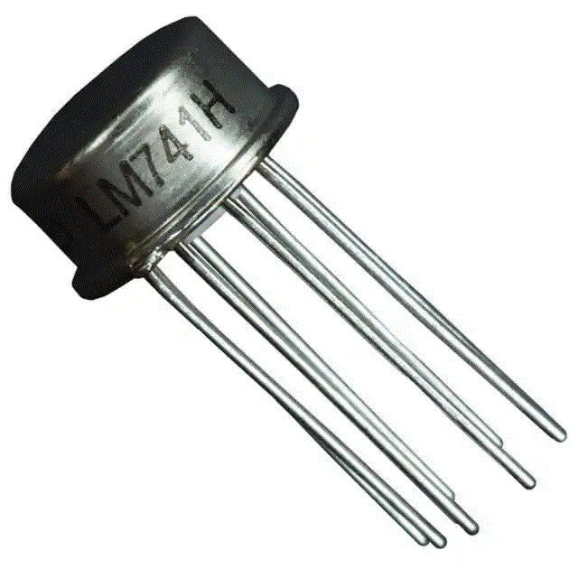 LM741H Operational Amplifier: Pinout, Datasheet, and Functional Block Diagram
27 July 20216568
 INA126P Precision Instrumentation Amplifier: Application, Feature and Datasheet
16 August 20244394
 XC6SLX150T-3FGG676I vs XC6SLX150-2FGG900I 2025 FPGA Comparison Guide
07 June 2025276
 1N5062 Diode: Features, Pinout, and Datasheet
18 January 20222527
 ATmega328P Series: 8-bit AVR Microcontroller Design Guide
15 January 20261635
 AD7768 24-Bit 8-Channel ADC: High-Speed Simultaneous Sampling Deep Dive
10 March 2026945
 MAX6675 Type-K Thermocouple Converter : Datasheet, Pinout, Comparison
14 September 202111547
 CD4049 Buffer and Converter IC: Pinout, Equivalent and Datasheet
28 August 20216948
 How to make an Obstacle Avoiding Robot?
29 August 202315210
 What is Mini LED?
08 December 20206524
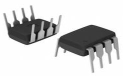
 What is a Digital Integrated Circuit and How Do We Use It?
20 October 202518855
 Japan's Three-Stage Strategy to Revive the Semiconductor Industry
01 April 20228270
 What are Comparators?
03 December 20206119
 Chip Packaging Lead Time Has Grown to 50 Weeks
07 April 20226103
 Insulation Approaches for Power Electronic Converters
12 October 20234546
 What is a Fixed Inductor?
15 April 202113277
Toshiba Semiconductor and Storage
In Stock: 20
Minimum: 1 Multiples: 1
Qty
Unit Price
Ext Price
1
$0.403303
$0.40
10
$0.380475
$3.80
100
$0.358939
$35.89
500
$0.338621
$169.31
1000
$0.319454
$319.45
Not the price you want? Send RFQ Now and we'll contact you ASAP.
Inquire for More Quantity
![74VHC373FT(BJ)]() 74VHC373FT(BJ)
74VHC373FT(BJ)Toshiba
![74LCX573FT]() 74LCX573FT
74LCX573FTToshiba Semiconductor and Storage
![74LCX373FT]() 74LCX373FT
74LCX373FTToshiba Semiconductor and Storage
![74VHC573FT]() 74VHC573FT
74VHC573FTToshiba Semiconductor and Storage
![74VHC373FT]() 74VHC373FT
74VHC373FTToshiba Semiconductor and Storage
![TC74LCX573FTEL]() TC74LCX573FTEL
TC74LCX573FTELToshiba
![74VHC573FT(BE)]() 74VHC573FT(BE)
74VHC573FT(BE)Toshiba
![74HC259D]() 74HC259D
74HC259DToshiba Semiconductor and Storage
![TC74VHCT373AFTEL]() TC74VHCT373AFTEL
TC74VHCT373AFTELToshiba Semiconductor and Storage
![74VHCT573AFT(BE)]() 74VHCT573AFT(BE)
74VHCT573AFT(BE)Toshiba


