
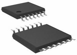
74HC157 Quad 2-input Multiplexer: Pinout, Datasheet and Circuit

16 Terminations 2V~6V 16 Pin 74HC157 Signal switch 74HC Series 4 Outputs 4 Functions
Unit Price: $0.355000
Ext Price: $0.36


16 Terminations 2V~6V 16 Pin 74HC157 Signal switch 74HC Series 4 Outputs 4 Functions
74HC157 is a 2-input (2:1) Multiplexer IC. It has four similar multiplexers inside it and hence it is called Quad package 2-Input Multiplexer. This article is going to explain pinout, datasheet, equivalent, circuit, and other details about 74HC157 Multiplexer. Furthermore, there is a huge range of semiconductors, capacitors, resistors, and ICs in stock. Welcome your RFQ!

74HC157 Quad 2x1 Multiplexer IC Proteus Simulation
- 74HC157 Pinout
- 74HC157 Description
- 74HC157 CAD Model
- 74HC157 Block Diagram
- Specifications
- 74HC157 Features and Benefits
- Alternatives for 74HC157
- 74HC157 Equivalent
- 74HC157 Applications
- Where to Use 74HC157 Multiplexer
- How to Use 74HC157 Multiplexer
- 74HC157 Dimensions
- 74HC157 Manufacturer
- Parts with Similar Specs
- Trend Analysis
- Datasheet PDF
74HC157 Pinout

74HC157 Pinout
| Pin Number | Pin Name | Description |
| 2,5,11,14 | Input A | This is the first input line of the 2:1 Multiplexer |
| 3,6,10,13 | Input B | This is the second input line of the 2:1 Multiplexer |
| 4,7,9,12 | Output Y | This is the output line pin of the Multiplexer |
| 1 | Line Select (S) | The select pin selects one of the two input lines and gives it to the output line |
| 15 | Enable (E) | Active low pin. Grounded for normal operation |
| 8 | Ground | Connected to the ground of the system |
| 16 | Vcc | This pin powers the IC, typically +5V is used. |
74HC157 Description
The 74HC157 multiplexer is a high-speed integrated circuit that has four digital multiplexers with two inputs each. This IC employs sophisticated Si gate CMOS technology and is well-matched by Schottky TTL with lower power consumption.
The 74HC157 multiplexer has two inputs: enable and choose, as well as two sets of registers. The chosen input determines which register the data is received from. Its function is determined throughout a temperature range of -55 °C to 125 °C.
74HC157 CAD Model

74HC157 Symbol

74HC157 Footprint
74HC157 Block Diagram

74HC157 Logic Diagram

74HC157 Logic Symbol
Specifications
- TypeParameter
- Factory Lead Time4 Weeks
- Contact Plating
Contact plating (finish) provides corrosion protection for base metals and optimizes the mechanical and electrical properties of the contact interfaces.
Gold - Mount
In electronic components, the term "Mount" typically refers to the method or process of physically attaching or fixing a component onto a circuit board or other electronic device. This can involve soldering, adhesive bonding, or other techniques to secure the component in place. The mounting process is crucial for ensuring proper electrical connections and mechanical stability within the electronic system. Different components may have specific mounting requirements based on their size, shape, and function, and manufacturers provide guidelines for proper mounting procedures to ensure optimal performance and reliability of the electronic device.
Surface Mount - Mounting Type
The "Mounting Type" in electronic components refers to the method used to attach or connect a component to a circuit board or other substrate, such as through-hole, surface-mount, or panel mount.
Surface Mount - Package / Case
refers to the protective housing that encases an electronic component, providing mechanical support, electrical connections, and thermal management.
16-SOIC (0.154, 3.90mm Width) - Number of Pins16
- Operating Temperature
The operating temperature is the range of ambient temperature within which a power supply, or any other electrical equipment, operate in. This ranges from a minimum operating temperature, to a peak or maximum operating temperature, outside which, the power supply may fail.
-40°C~125°C - Packaging
Semiconductor package is a carrier / shell used to contain and cover one or more semiconductor components or integrated circuits. The material of the shell can be metal, plastic, glass or ceramic.
Tape & Reel (TR) - Series
In electronic components, the "Series" refers to a group of products that share similar characteristics, designs, or functionalities, often produced by the same manufacturer. These components within a series typically have common specifications but may vary in terms of voltage, power, or packaging to meet different application needs. The series name helps identify and differentiate between various product lines within a manufacturer's catalog.
74HC - Published2013
- JESD-609 Code
The "JESD-609 Code" in electronic components refers to a standardized marking code that indicates the lead-free solder composition and finish of electronic components for compliance with environmental regulations.
e4 - Part Status
Parts can have many statuses as they progress through the configuration, analysis, review, and approval stages.
Active - Moisture Sensitivity Level (MSL)
Moisture Sensitivity Level (MSL) is a standardized rating that indicates the susceptibility of electronic components, particularly semiconductors, to moisture-induced damage during storage and the soldering process, defining the allowable exposure time to ambient conditions before they require special handling or baking to prevent failures
1 (Unlimited) - Number of Terminations16
- TypeMultiplexer
- Voltage - Supply
Voltage - Supply refers to the range of voltage levels that an electronic component or circuit is designed to operate with. It indicates the minimum and maximum supply voltage that can be applied for the device to function properly. Providing supply voltages outside this range can lead to malfunction, damage, or reduced performance. This parameter is critical for ensuring compatibility between different components in a circuit.
2V~6V - Terminal Position
In electronic components, the term "Terminal Position" refers to the physical location of the connection points on the component where external electrical connections can be made. These connection points, known as terminals, are typically used to attach wires, leads, or other components to the main body of the electronic component. The terminal position is important for ensuring proper connectivity and functionality of the component within a circuit. It is often specified in technical datasheets or component specifications to help designers and engineers understand how to properly integrate the component into their circuit designs.
DUAL - Terminal Form
Occurring at or forming the end of a series, succession, or the like; closing; concluding.
GULL WING - Peak Reflow Temperature (Cel)
Peak Reflow Temperature (Cel) is a parameter that specifies the maximum temperature at which an electronic component can be exposed during the reflow soldering process. Reflow soldering is a common method used to attach electronic components to a circuit board. The Peak Reflow Temperature is crucial because it ensures that the component is not damaged or degraded during the soldering process. Exceeding the specified Peak Reflow Temperature can lead to issues such as component failure, reduced performance, or even permanent damage to the component. It is important for manufacturers and assemblers to adhere to the recommended Peak Reflow Temperature to ensure the reliability and functionality of the electronic components.
260 - Number of Functions4
- Supply Voltage
Supply voltage refers to the electrical potential difference provided to an electronic component or circuit. It is crucial for the proper operation of devices, as it powers their functions and determines performance characteristics. The supply voltage must be within specified limits to ensure reliability and prevent damage to components. Different electronic devices have specific supply voltage requirements, which can vary widely depending on their design and intended application.
5V - Time@Peak Reflow Temperature-Max (s)
Time@Peak Reflow Temperature-Max (s) refers to the maximum duration that an electronic component can be exposed to the peak reflow temperature during the soldering process, which is crucial for ensuring reliable solder joint formation without damaging the component.
30 - Base Part Number
The "Base Part Number" (BPN) in electronic components serves a similar purpose to the "Base Product Number." It refers to the primary identifier for a component that captures the essential characteristics shared by a group of similar components. The BPN provides a fundamental way to reference a family or series of components without specifying all the variations and specific details.
74HC157 - Pin Count
a count of all of the component leads (or pins)
16 - Number of Outputs4
- Operating Supply Voltage
The voltage level by which an electrical system is designated and to which certain operating characteristics of the system are related.
5V - Circuit
The parameter "Circuit" in electronic components refers to the interconnected arrangement of various electronic elements such as resistors, capacitors, inductors, and active devices like transistors. It defines the path through which electric current flows and establishes the operational behavior of the components within that system. Circuits can be classified as analog or digital, depending on the type of signals they handle, and can vary in complexity from simple series or parallel configurations to intricate designs used in advanced applications.
4 x 2:1 - Supply Voltage-Max (Vsup)
The parameter "Supply Voltage-Max (Vsup)" in electronic components refers to the maximum voltage that can be safely applied to the component without causing damage. It is an important specification to consider when designing or using electronic circuits to ensure the component operates within its safe operating limits. Exceeding the maximum supply voltage can lead to overheating, component failure, or even permanent damage. It is crucial to adhere to the specified maximum supply voltage to ensure the reliable and safe operation of the electronic component.
6V - Supply Voltage-Min (Vsup)
The parameter "Supply Voltage-Min (Vsup)" in electronic components refers to the minimum voltage level required for the component to operate within its specified performance range. This parameter indicates the lowest voltage that can be safely applied to the component without risking damage or malfunction. It is crucial to ensure that the supply voltage provided to the component meets or exceeds this minimum value to ensure proper functionality and reliability. Failure to adhere to the specified minimum supply voltage may result in erratic behavior, reduced performance, or even permanent damage to the component.
2V - Load Capacitance
the amount of capacitance measured or computed across the crystal terminals on the PCB. Frequency Tolerance. Frequency tolerance refers to the allowable deviation from nominal, in parts per million (PPM), at a specific temperature, usually +25°C.
50pF - Propagation Delay
the flight time of packets over the transmission link and is limited by the speed of light.
21 ns - Family
In electronic components, the parameter "Family" typically refers to a categorization or classification system used to group similar components together based on their characteristics, functions, or applications. This classification helps users easily identify and select components that meet their specific requirements. The "Family" parameter can include various subcategories such as resistors, capacitors, diodes, transistors, integrated circuits, and more. Understanding the "Family" of an electronic component can provide valuable information about its compatibility, performance specifications, and potential uses within a circuit or system. It is important to consider the "Family" parameter when designing or troubleshooting electronic circuits to ensure proper functionality and compatibility with other components.
HC/UH - Supply Type
Supply Type in electronic components refers to the classification of power sources used to operate the component. It indicates whether the component requires DC or AC power, and if DC, specifies the voltage levels such as low, medium, or high. Different supply types can affect the performance, compatibility, and application of the component in electronic circuits. Understanding the supply type is crucial for proper component selection and integration into electronic designs.
Single - Output Polarity
Output polarity in electronic components refers to the orientation of the output signal in relation to the ground or reference voltage. It indicates whether the output voltage is positive or negative with respect to the ground. Positive output polarity means the signal is higher than the ground potential, while negative output polarity signifies that the signal is lower than the ground. This characteristic is crucial for determining compatibility with other components in a circuit and ensuring proper signal processing.
TRUE - Number of Input Lines8
- Voltage Supply Source
A voltage source is a two-terminal device which can maintain a fixed voltage. An ideal voltage source can maintain the fixed voltage independent of the load resistance or the output current. However, a real-world voltage source cannot supply unlimited current. A voltage source is the dual of a current source.
Single Supply - Independent Circuits
The term "Independent Circuits" in electronic components refers to the ability of a device to function as a separate and self-contained circuit within a larger system. In the context of electronic components, having independent circuits means that each circuit can operate autonomously without being directly affected by other circuits in the system. This feature allows for better isolation, control, and troubleshooting of individual circuits within a complex electronic system. Independent circuits are commonly found in devices such as integrated circuits, where multiple functional blocks are designed to operate independently to perform specific tasks efficiently. Overall, the presence of independent circuits in electronic components enhances the reliability, flexibility, and performance of the system as a whole.
1 - Length9.9mm
- Width3.9mm
- REACH SVHC
The parameter "REACH SVHC" in electronic components refers to the compliance with the Registration, Evaluation, Authorization, and Restriction of Chemicals (REACH) regulation regarding Substances of Very High Concern (SVHC). SVHCs are substances that may have serious effects on human health or the environment, and their use is regulated under REACH to ensure their safe handling and minimize their impact.Manufacturers of electronic components need to declare if their products contain any SVHCs above a certain threshold concentration and provide information on the safe use of these substances. This information allows customers to make informed decisions about the potential risks associated with using the components and take appropriate measures to mitigate any hazards.Ensuring compliance with REACH SVHC requirements is essential for electronics manufacturers to meet regulatory standards, protect human health and the environment, and maintain transparency in their supply chain. It also demonstrates a commitment to sustainability and responsible manufacturing practices in the electronics industry.
No SVHC - Radiation Hardening
Radiation hardening is the process of making electronic components and circuits resistant to damage or malfunction caused by high levels of ionizing radiation, especially for environments in outer space (especially beyond the low Earth orbit), around nuclear reactors and particle accelerators, or during nuclear accidents or nuclear warfare.
No - RoHS Status
RoHS means “Restriction of Certain Hazardous Substances” in the “Hazardous Substances Directive” in electrical and electronic equipment.
ROHS3 Compliant - Lead Free
Lead Free is a term used to describe electronic components that do not contain lead as part of their composition. Lead is a toxic material that can have harmful effects on human health and the environment, so the electronics industry has been moving towards lead-free components to reduce these risks. Lead-free components are typically made using alternative materials such as silver, copper, and tin. Manufacturers must comply with regulations such as the Restriction of Hazardous Substances (RoHS) directive to ensure that their products are lead-free and environmentally friendly.
Lead Free
74HC157 Features and Benefits
Low-power dissipation
Complies with JEDEC standard no. 7A
Input levels: For 74HC157: CMOS level
For 74HCT157: TTL level
Non-inverting data path
ESD protection: HBM JESD22-A114F exceeds 2 000 V
MM JESD22-A115-A exceeds 200 V
Specified from 40 C to +85 C and from 40 C to +125 C
High noise immunity
It selects 4-bits of data using two sources under a common data select input control.
The enable (E) input pin is active LOW. Once enable pin (E) is HIGH, then outputs are LOW apart from all other input states.
Package Type is DIP
Voltage rating ranges from 2V to 6V
The current rating is less like 1µA
Rating of Temperature ranges from -55 to 125 o C
Number of Pins-16
Alternatives for 74HC157
SN74LS153, 74LV4053, CD4053, MPC507AU
74HC157 Equivalent
CY74FCT257T
74HC157 Applications
Memory of Computer
Communication Systems
ALUs (Arithmetic Logic Units)
Telephone Line Selector
Network Lines
Where to Use 74HC157 Multiplexer
The 74HC157 is a two-input (2:1) multiplexer integrated circuit. It is known as a Quad package 2-Input Multiplexer because it contains four comparable multiplexers. As we all know, a multiplexer takes two or more inputs and outputs one of them based on the Select line state.
Even though it contains four mux, we are unable to manage each multiplexer separately because all multiplexers are controlled by a single select line. If you need more than one 21 multiplexers in a chip and wish to control each multiplexer with a single select line, this is the best option.
The 74HC157 multiplexer IC is primarily used for multiplexing data in communication channels that would otherwise be unusable. This IC contains four multiplexers with two input pins that can be used in computer memory ALUs as well as to perform Boolean functions.
How to Use 74HC157 Multiplexer
It's quite simple to use the 74HC157 IC. The IC's operational voltage ranges from 2 to 6 volts, so choose one (usually 5 volts) and power it with the Vcc and Ground pins. For regular IC functioning, the Enable pin must be connected to the ground. Therefore, you can either ground it permanently or link it to an MCU/MPU to turn on or off the Multiplexers as needed.
This IC contains four 2:1 multiplexers, but for the sake of simplicity, we'll assume we're just utilizing one of them. Because the multiplexer is a 2:1 multiplexer, it can accept two inputs. These two inputs are connected to the pins Input A (also known as Input I0) and Input B (also known as Input I1). The multiplexer's output is connected to the output pin Y. The chosen line (pin 1) determines which of the two inputs goes to the output pin. Input A will be reflected on the output pin Y if the Select Line is low (logic 0), and Input B will be reflected on the output pin Y if the Select Line is high (logic 1). The following is a 74HC157 multiplexer circuit.

74HC157 multiplexer circuit
This IC contains four 2:1 multiplexers, but for the sake of simplicity, we'll assume we're just utilizing one of them. Because the multiplexer is a 2:1 multiplexer, it can accept two inputs. These two inputs are connected to the pins Input A (also known as Input I0) and Input B (also known as Input I1). The multiplexer's output is connected to the output pin Y. The chosen line (pin 1) determines which of the two inputs goes to the output pin. Input A will be reflected on the output pin Y if the Select Line is low (logic 0), and Input B will be reflected on the output pin Y if the Select Line is high (logic 1).
| Enable | Select I/P | Data Inputs | Data Inputs | Output (157) | Output (158) |
| E’ | S | I0 | I1 | Y | Y’ |
| H | X | X | X | L | H |
| L | L | L | X | L | H |
| L | L | H | X | H | L |
| L | H | X | L | L | H |
| L | H | X | H | H | L |
74HC157 Dimensions

74HC157 Dimensions
74HC157 Manufacturer
Nexperia is dedicated to Discretes, Logic, and MOSFETs devices. This new company became independent at the beginning of 2017.
Parts with Similar Specs
- ImagePart NumberManufacturerPackage / CaseNumber of PinsNumber of OutputsSupply TypeSupply VoltageRoHS StatusMoisture Sensitivity Level (MSL)Pin CountView Compare
![74HC157D,653]()
74HC157D,653
16-SOIC (0.154, 3.90mm Width)
16
4
Single
5 V
ROHS3 Compliant
1 (Unlimited)
16
![CD4532BNSR]()
16-SOIC (0.209, 5.30mm Width)
16
3
Dual
5 V
ROHS3 Compliant
1 (Unlimited)
16
![NX5DV330D,118]()
16-SOIC (0.154, 3.90mm Width)
-
1
-
5 V
ROHS3 Compliant
1 (Unlimited)
16
![N74F157AD,623]()
16-SOIC (0.154, 3.90mm Width)
-
2
-
5 V
ROHS3 Compliant
1 (Unlimited)
16


Trend Analysis
Datasheet PDF
- PCN Packaging :
- PCN Design/Specification :
- Datasheets :
- PCN Assembly/Origin :
- ReachStatement :
What is the use of 74HC157?
74HC157 multiplexer IC is mainly used for multiplexing the data otherwise in communication lines. This IC includes 4 multiplexers with two input pins which can be used in ALU's of computer memory and it can also be utilized to execute Boolean functions.
How does 74HC157 work?
74HC157 multiplexer is a high-speed IC or integrated circuit that includes four 2-inputs based digital multiplexers. This IC uses an advanced Si gate CMOS technology and is well-matched through less power Schottky TTL. 74HC157 multiplexer includes two inputs like enable & select input and also two groups of registers.
Where do we use multiplexer?
Multiplexers are used in various applications wherein multiple-data need to be transmitted by using a single line.
 C2482 NPN Transistor: C2482 Equivalent, Pinout, Uses
11 April 202215284
 TL071CD Operational Amplifier: Pinout, Specification, and Datasheet
16 August 20242869
 An Introduction for Motor Driver IC ULN2003
25 April 202228951
 TPS54302DDCR: Synchronous Buck Converter, Pinout
25 February 20224529
 What you need to know about TPA3110 Bluetooth Audio Power Amplifier Board
26 April 202216276
 TE Connectivity 172165-1: Small Plug, Big Impact
30 September 2025525
 LMV358 Operational Amplifiers: Pinout, Datasheet and LMV358 vs. LM358
09 November 20219345
 MIC2042 High-side MOSFET Switch: Pinout, Equivalent and Datasheet
01 April 2022559
 What is Electronic Ballast?
28 September 202013060
 What is a Schmitt Trigger?
09 December 20216903
 How to Select a Digital Isolator?
12 April 20214884
 Stepper Motor: Types, Working and Applications
26 December 20258542
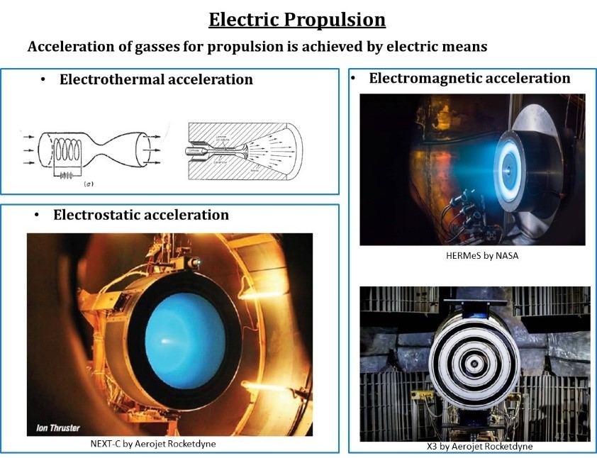 The Role of SiC in Extended Space Missions
20 September 20242035
 RF Switches Guide: Types, Specifications & Applications
03 July 20251952
 C1815 vs C945 Key Features and Application Guide
01 September 20251013
 What is a Synchronous Motor?
16 March 20215016
Nexperia USA Inc.
In Stock: 200
Minimum: 1 Multiples: 1
Qty
Unit Price
Ext Price
1
$0.355000
$0.36
10
$0.334906
$3.35
100
$0.315949
$31.59
500
$0.298065
$149.03
1000
$0.281194
$281.19
Not the price you want? Send RFQ Now and we'll contact you ASAP.
Inquire for More Quantity
![74HC138D,653]() 74HC138D,653
74HC138D,653Nexperia USA Inc.
![74HC138PW,118]() 74HC138PW,118
74HC138PW,118Nexperia USA Inc.
![74HC151D,653]() 74HC151D,653
74HC151D,653Nexperia USA Inc.
![74CBTLV3384PW,118]() 74CBTLV3384PW,118
74CBTLV3384PW,118Nexperia USA Inc.
![74HC154PW,118]() 74HC154PW,118
74HC154PW,118Nexperia USA Inc.
![74HCT138D,653]() 74HCT138D,653
74HCT138D,653Nexperia USA Inc.
![74LVC1G157GW,125]() 74LVC1G157GW,125
74LVC1G157GW,125Nexperia USA Inc.
![74HC251D,653]() 74HC251D,653
74HC251D,653Nexperia USA Inc.
![74HC238D,653]() 74HC238D,653
74HC238D,653Nexperia USA Inc.


