
 Product
 Brand
Brand Articles
 Tools
Tools
AMC1311 Reinforced Isolated Amplifiers: Datasheet, Applications and Equivalents


8 Amplifier AMC1311 8 Pin 3.3V 8-SOIC (0.295, 7.50mm Width)
The AMC1311 is a precision, isolated amplifier with an isolation barrier that is highly resistant to magnetic interference between the output and the input circuitry. This article will cover pinout, datasheet, applications, features, and other details about AMC1311 amplifiers.

Current sensing with different types of amplifiers
What is AMC1311?
The AMC1311 device is a precision, isolated amplifier with an isolation barrier that is highly resistant to magnetic interference between the output and the input circuitry. According to VDE V 0884-11 and UL1577, this barrier is certified to provide reinforced galvanic isolation of up to 7 kV peak. This isolated amplifier separates portions of the system that run on different common-mode voltage levels and protects lower-voltage parts from damage when used in conjunction with an isolated power supply.
The AMC1311 device has a high-impedance input that is designed for use with high-voltage resistive dividers or other voltage signal sources with high output resistance. The high-performance of the AMC1311 Amplifiers enables accurate, low-temperature drift voltage or temperature sensing and control in closed-loop systems.
AMC1311 Pinout

AMC1311 Pinout
AMC1311 CAD Model

AMC1311 Symbol

AMC1311 Footprint

AMC1311 3D Model
Specifications
- TypeParameter
- Lifecycle Status
Lifecycle Status refers to the current stage of an electronic component in its product life cycle, indicating whether it is active, obsolete, or transitioning between these states. An active status means the component is in production and available for purchase. An obsolete status indicates that the component is no longer being manufactured or supported, and manufacturers typically provide a limited time frame for support. Understanding the lifecycle status is crucial for design engineers to ensure continuity and reliability in their projects.
ACTIVE (Last Updated: 6 days ago) - Factory Lead Time12 Weeks
- Mounting Type
The "Mounting Type" in electronic components refers to the method used to attach or connect a component to a circuit board or other substrate, such as through-hole, surface-mount, or panel mount.
Surface Mount - Package / Case
refers to the protective housing that encases an electronic component, providing mechanical support, electrical connections, and thermal management.
8-SOIC (0.295, 7.50mm Width) - Surface Mount
having leads that are designed to be soldered on the side of a circuit board that the body of the component is mounted on.
YES - Number of Pins8
- Packaging
Semiconductor package is a carrier / shell used to contain and cover one or more semiconductor components or integrated circuits. The material of the shell can be metal, plastic, glass or ceramic.
Tube - JESD-609 Code
The "JESD-609 Code" in electronic components refers to a standardized marking code that indicates the lead-free solder composition and finish of electronic components for compliance with environmental regulations.
e4 - Pbfree Code
The "Pbfree Code" parameter in electronic components refers to the code or marking used to indicate that the component is lead-free. Lead (Pb) is a toxic substance that has been widely used in electronic components for many years, but due to environmental concerns, there has been a shift towards lead-free alternatives. The Pbfree Code helps manufacturers and users easily identify components that do not contain lead, ensuring compliance with regulations and promoting environmentally friendly practices. It is important to pay attention to the Pbfree Code when selecting electronic components to ensure they meet the necessary requirements for lead-free applications.
yes - Part Status
Parts can have many statuses as they progress through the configuration, analysis, review, and approval stages.
Active - Moisture Sensitivity Level (MSL)
Moisture Sensitivity Level (MSL) is a standardized rating that indicates the susceptibility of electronic components, particularly semiconductors, to moisture-induced damage during storage and the soldering process, defining the allowable exposure time to ambient conditions before they require special handling or baking to prevent failures
3 (168 Hours) - Number of Terminations8
- TypeIsolation
- Terminal Finish
Terminal Finish refers to the surface treatment applied to the terminals or leads of electronic components to enhance their performance and longevity. It can improve solderability, corrosion resistance, and overall reliability of the connection in electronic assemblies. Common finishes include nickel, gold, and tin, each possessing distinct properties suitable for various applications. The choice of terminal finish can significantly impact the durability and effectiveness of electronic devices.
Nickel/Palladium/Gold (Ni/Pd/Au) - Max Operating Temperature
The Maximum Operating Temperature is the maximum body temperature at which the thermistor is designed to operate for extended periods of time with acceptable stability of its electrical characteristics.
125°C - Min Operating Temperature
The "Min Operating Temperature" parameter in electronic components refers to the lowest temperature at which the component is designed to operate effectively and reliably. This parameter is crucial for ensuring the proper functioning and longevity of the component, as operating below this temperature may lead to performance issues or even damage. Manufacturers specify the minimum operating temperature to provide guidance to users on the environmental conditions in which the component can safely operate. It is important to adhere to this parameter to prevent malfunctions and ensure the overall reliability of the electronic system.
-55°C - Terminal Position
In electronic components, the term "Terminal Position" refers to the physical location of the connection points on the component where external electrical connections can be made. These connection points, known as terminals, are typically used to attach wires, leads, or other components to the main body of the electronic component. The terminal position is important for ensuring proper connectivity and functionality of the component within a circuit. It is often specified in technical datasheets or component specifications to help designers and engineers understand how to properly integrate the component into their circuit designs.
DUAL - Terminal Form
Occurring at or forming the end of a series, succession, or the like; closing; concluding.
GULL WING - Peak Reflow Temperature (Cel)
Peak Reflow Temperature (Cel) is a parameter that specifies the maximum temperature at which an electronic component can be exposed during the reflow soldering process. Reflow soldering is a common method used to attach electronic components to a circuit board. The Peak Reflow Temperature is crucial because it ensures that the component is not damaged or degraded during the soldering process. Exceeding the specified Peak Reflow Temperature can lead to issues such as component failure, reduced performance, or even permanent damage to the component. It is important for manufacturers and assemblers to adhere to the recommended Peak Reflow Temperature to ensure the reliability and functionality of the electronic components.
NOT SPECIFIED - Number of Functions1
- Supply Voltage
Supply voltage refers to the electrical potential difference provided to an electronic component or circuit. It is crucial for the proper operation of devices, as it powers their functions and determines performance characteristics. The supply voltage must be within specified limits to ensure reliability and prevent damage to components. Different electronic devices have specific supply voltage requirements, which can vary widely depending on their design and intended application.
3.3V - Time@Peak Reflow Temperature-Max (s)
Time@Peak Reflow Temperature-Max (s) refers to the maximum duration that an electronic component can be exposed to the peak reflow temperature during the soldering process, which is crucial for ensuring reliable solder joint formation without damaging the component.
NOT SPECIFIED - Base Part Number
The "Base Part Number" (BPN) in electronic components serves a similar purpose to the "Base Product Number." It refers to the primary identifier for a component that captures the essential characteristics shared by a group of similar components. The BPN provides a fundamental way to reference a family or series of components without specifying all the variations and specific details.
AMC1311 - Temperature Grade
Temperature grades represent a tire's resistance to heat and its ability to dissipate heat when tested under controlled laboratory test conditions.
MILITARY - Number of Channels1
- Max Supply Voltage
In general, the absolute maximum common-mode voltage is VEE-0.3V and VCC+0.3V, but for products without a protection element at the VCC side, voltages up to the absolute maximum rated supply voltage (i.e. VEE+36V) can be supplied, regardless of supply voltage.
5.5V - Min Supply Voltage
The minimum supply voltage (V min ) is explored for sequential logic circuits by statistically simulating the impact of within-die process variations and gate-dielectric soft breakdown on data retention and hold time.
3V - Input Offset Voltage (Vos)
Input Offset Voltage (Vos) is a key parameter in electronic components, particularly in operational amplifiers. It refers to the voltage difference that must be applied between the two input terminals of the amplifier to nullify the output voltage when the input terminals are shorted together. In simpler terms, it represents the voltage required to bring the output of the amplifier to zero when there is no input signal present. Vos is an important parameter as it can introduce errors in the output signal of the amplifier, especially in precision applications where accuracy is crucial. Minimizing Vos is essential to ensure the amplifier operates with high precision and accuracy.
-1.1mV - Bandwidth
In electronic components, "Bandwidth" refers to the range of frequencies over which the component can effectively operate or pass signals without significant loss or distortion. It is a crucial parameter for devices like amplifiers, filters, and communication systems. The bandwidth is typically defined as the difference between the upper and lower frequencies at which the component's performance meets specified criteria, such as a certain level of signal attenuation or distortion. A wider bandwidth indicates that the component can handle a broader range of frequencies, making it more versatile for various applications. Understanding the bandwidth of electronic components is essential for designing and optimizing circuits to ensure proper signal transmission and reception within the desired frequency range.
275 kHz - -3db Bandwidth
The "-3dB bandwidth" of an electronic component refers to the frequency range over which the component's output signal power is reduced by 3 decibels (dB) compared to its maximum output power. This parameter is commonly used to describe the frequency response of components such as amplifiers, filters, and other signal processing devices. The -3dB point is significant because it represents the half-power point, where the output signal power is reduced to half of its maximum value. Understanding the -3dB bandwidth is important for designing and analyzing electronic circuits to ensure that signals are accurately processed within the desired frequency range.
275MHz - Input Bias Current
Input Bias Current refers to the small amount of current that flows into the input terminals of an electronic component, such as an operational amplifier. It is primarily caused by the input impedance of the device and the characteristics of the transistors within it. This current is crucial in determining the accuracy of the analog signal processing, as it can affect the level of voltage offset and signal integrity in the application. In many precise applications, minimizing input bias current is essential to achieve optimal performance.
3.5nA - Isolation Voltage
Isolation voltage refers to a test of the ability of an insulator to minimize the flow of electric current with a high applied voltage.
1.5kV - Max Junction Temperature (Tj)
Max Junction Temperature (Tj) refers to the maximum allowable temperature at the junction of a semiconductor device, such as a transistor or integrated circuit. It is a critical parameter that influences the performance, reliability, and lifespan of the component. Exceeding this temperature can lead to thermal runaway, breakdown, or permanent damage to the device. Proper thermal management is essential to ensure the junction temperature remains within safe operating limits during device operation.
150°C - Ambient Temperature Range High
This varies from person to person, but it is somewhere between 68 and 77 degrees F on average. The temperature setting that is comfortable for an individual may fluctuate with humidity and outside temperature as well. The temperature of an air conditioned room can also be considered ambient temperature.
125°C - Non-linearity-Max
Non-linearity-Max is a parameter used to describe the maximum level of non-linearity exhibited by an electronic component or system. Non-linearity refers to the deviation of the component's output from a straight line when compared to its input signal. In the context of electronic components, such as amplifiers or sensors, non-linearity can introduce distortion or inaccuracies in the output signal. The "Non-linearity-Max" parameter specifies the maximum amount of deviation allowed before the component is considered to be operating outside of its specified linear range. It is an important characteristic to consider when designing or selecting components for applications where precise and accurate signal processing is required.
0.04% - Height2.8mm
- Length5.85mm
- Width7.5mm
- Thickness
Thickness in electronic components refers to the measurement of how thick a particular material or layer is within the component structure. It can pertain to various aspects, such as the thickness of a substrate, a dielectric layer, or conductive traces. This parameter is crucial as it impacts the electrical, mechanical, and thermal properties of the component, influencing its performance and reliability in electronic circuits.
2.65mm - RoHS Status
RoHS means “Restriction of Certain Hazardous Substances” in the “Hazardous Substances Directive” in electrical and electronic equipment.
ROHS3 Compliant
AMC1311 Features
2-V, high-impedance input voltage range optimized for isolated voltage measurement
Low offset error and drift:
AMC1311B: ±1.5 mV (max), ±10 µV/°C (max)
AMC1311: ±9.9 mV (max), ±20 µV/°C (typ)
Fixed gain: 1
Very low gain error and drift:
AMC1311B: ±0.2% (max), ±40 ppm/°C (max)
AMC1311: ±1% (max), ±30 ppm/°C (typ)
Low nonlinearity and drift: 0.01%, 1 ppm/°C (typ)
3.3-V operation on high-side (AMC1311B)
Missing high-side supply indication
Safety-related certifications:
7000-VPK reinforced isolation per DIN VDE V 0884-11: 2017-01
5000-VRMS isolation for 1 Minute per UL1577
CAN/CSA no. 5A-component acceptance service notice and IEC 62368-1 end equipment standard
AMC1311 Internal Schematics

AMC1311 Internal Schematics
AMC1311 Applications
Isolated voltage sensing in:
motor drives
frequency inverters
uninterruptible power supplies
Where to use isolated amplifier?
The primary purpose of an isolation amplifier is to lower the common voltage between the source and the power load. They operate as electrical safety barriers and provide electrical isolation. They're also utilized to keep the operators safe from current leakage. These are a few of the most commonly utilized gadgets.
How to use isolated amplifier?
Isolation amplifiers provide galvanic separation between their inputs and outputs, ensuring that only the appropriate signals are transmitted and that large common-mode voltages are avoided. The ground separation between sensors is maintained in sensor-based monitoring systems to avoid ground loops.
AMC1311 Dimensions


AMC1311 Dimensions
AMC1311 Manufacturer
Texas Instruments Incorporated (TI) is an American technology company headquartered in Dallas, Texas, that designs and manufactures semiconductors and various integrated circuits, which it sells to electronics designers and manufacturers globally. It is one of the top 10 semiconductor companies worldwide based on sales volume.
What is AMC1311 used for?
The AMC1311 is an isolated amplifier that is used in conjunction with the isolated power supply to separate portions of the system that run on different common-mode voltage levels and safeguard lower-voltage parts from harm.
What is the voltage of AMC1311?
3.3V
What is the operating temperatures of AMC1311?
-55°C-125°C
How does isolation amplifier work?
Isolation amplifiers provide galvanic separation between their inputs and outputs, ensuring that only the appropriate signals are transmitted and that large common-mode voltages are avoided. The ground separation between sensors is maintained in sensor-based monitoring systems to avoid ground loops.
What is the gain of an isolation amplifier?
An isolation amplifier or a unity gain amplifier provides isolation from one fraction of the circuit to another fraction.
 APX803S 3-Pin Microprocessor Reset Circuit: Pinout, Equivalent and Datasheet
02 March 20221717
 Analog Devices AD8065ARTZ-R2: Key Features and Applications
28 May 2025859
 Introduction to MSP430G2x11 and MSP430G2x01 Mixed-Signal Microcontrollers
29 February 2024141
 2N5089 Transistor : Pinout, Equivalent and Datasheet
07 September 20212802
 STM32F103C6T6 Microcontroller: 72MHz, 48-LQFP, Pinout and Datasheet
18 February 20228812
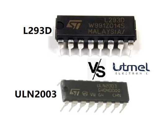 A Comparison Article about L293D & ULN2003
25 April 20227535
![LR41 Battery, LR41 Battery Equivalent, LR41 and SR41 Cell Battery [FAQ]](https://res.utmel.com/Images/Article/edaf2000-e788-42b0-b239-6f7d52115528.jpg) LR41 Battery, LR41 Battery Equivalent, LR41 and SR41 Cell Battery [FAQ]
LR41 Battery, LR41 Battery Equivalent, LR41 and SR41 Cell Battery [FAQ]20 December 202132779
![CD4007 CMOS Inverter: 14 SOIC Inverter, Pinout and Datasheet pdf [Video]](https://res.utmel.com/Images/Article/c2022e28-6851-4487-8983-58a7ba99db80.jpg) CD4007 CMOS Inverter: 14 SOIC Inverter, Pinout and Datasheet pdf [Video]
CD4007 CMOS Inverter: 14 SOIC Inverter, Pinout and Datasheet pdf [Video]07 January 20227172
 Surge Protector Best Practices for Everyday Use
10 July 20252204
 Introduction to EPROM and EEPROM
08 January 202617186
 FPGA Tutorial: A Beginner's Guide to Programmable Logic Design in 2025
15 April 20254529
 Norton's Theorem: Working Principle, Circuit Design, and Modern Applications
27 May 2026228
 Leading Fiber Optic Connectors Every Installer Should Know
17 July 20253068
 The Historical Milestones of Coaxial Cable Development
19 July 20253309
 Audio Transformer-Types, Functions and Working
05 January 202615097
 A Practical Methodology to Simulate 4H-SiC and GaN p-n Diodes with Model Parameter Adjustment in Medici
07 February 20234195
Texas Instruments
In Stock: 1280
United States
China
Canada
Japan
Russia
Germany
United Kingdom
Singapore
Italy
Hong Kong(China)
Taiwan(China)
France
Korea
Mexico
Netherlands
Malaysia
Austria
Spain
Switzerland
Poland
Thailand
Vietnam
India
United Arab Emirates
Afghanistan
Åland Islands
Albania
Algeria
American Samoa
Andorra
Angola
Anguilla
Antigua & Barbuda
Argentina
Armenia
Aruba
Australia
Azerbaijan
Bahamas
Bahrain
Bangladesh
Barbados
Belarus
Belgium
Belize
Benin
Bermuda
Bhutan
Bolivia
Bonaire, Sint Eustatius and Saba
Bosnia & Herzegovina
Botswana
Brazil
British Indian Ocean Territory
British Virgin Islands
Brunei
Bulgaria
Burkina Faso
Burundi
Cabo Verde
Cambodia
Cameroon
Cayman Islands
Central African Republic
Chad
Chile
Christmas Island
Cocos (Keeling) Islands
Colombia
Comoros
Congo
Congo (DRC)
Cook Islands
Costa Rica
Côte d’Ivoire
Croatia
Cuba
Curaçao
Cyprus
Czechia
Denmark
Djibouti
Dominica
Dominican Republic
Ecuador
Egypt
El Salvador
Equatorial Guinea
Eritrea
Estonia
Eswatini
Ethiopia
Falkland Islands
Faroe Islands
Fiji
Finland
French Guiana
French Polynesia
Gabon
Gambia
Georgia
Ghana
Gibraltar
Greece
Greenland
Grenada
Guadeloupe
Guam
Guatemala
Guernsey
Guinea
Guinea-Bissau
Guyana
Haiti
Honduras
Hungary
Iceland
Indonesia
Iran
Iraq
Ireland
Isle of Man
Israel
Jamaica
Jersey
Jordan
Kazakhstan
Kenya
Kiribati
Kosovo
Kuwait
Kyrgyzstan
Laos
Latvia
Lebanon
Lesotho
Liberia
Libya
Liechtenstein
Lithuania
Luxembourg
Macao(China)
Madagascar
Malawi
Maldives
Mali
Malta
Marshall Islands
Martinique
Mauritania
Mauritius
Mayotte
Micronesia
Moldova
Monaco
Mongolia
Montenegro
Montserrat
Morocco
Mozambique
Myanmar
Namibia
Nauru
Nepal
New Caledonia
New Zealand
Nicaragua
Niger
Nigeria
Niue
Norfolk Island
North Korea
North Macedonia
Northern Mariana Islands
Norway
Oman
Pakistan
Palau
Palestinian Authority
Panama
Papua New Guinea
Paraguay
Peru
Philippines
Pitcairn Islands
Portugal
Puerto Rico
Qatar
Réunion
Romania
Rwanda
Samoa
San Marino
São Tomé & Príncipe
Saudi Arabia
Senegal
Serbia
Seychelles
Sierra Leone
Sint Maarten
Slovakia
Slovenia
Solomon Islands
Somalia
South Africa
South Sudan
Sri Lanka
St Helena, Ascension, Tristan da Cunha
St. Barthélemy
St. Kitts & Nevis
St. Lucia
St. Martin
St. Pierre & Miquelon
St. Vincent & Grenadines
Sudan
Suriname
Svalbard & Jan Mayen
Sweden
Syria
Tajikistan
Tanzania
Timor-Leste
Togo
Tokelau
Tonga
Trinidad & Tobago
Tunisia
Turkey
Turkmenistan
Turks & Caicos Islands
Tuvalu
U.S. Outlying Islands
U.S. Virgin Islands
Uganda
Ukraine
Uruguay
Uzbekistan
Vanuatu
Vatican City
Venezuela
Wallis & Futuna
Yemen
Zambia
Zimbabwe
![AMC1311BDWVR]() AMC1311BDWVR
AMC1311BDWVRTexas Instruments
![AMC1311DWVR]() AMC1311DWVR
AMC1311DWVRTexas Instruments
![AMC1311DWV]() AMC1311DWV
AMC1311DWVTexas Instruments
![LM392M]() LM392M
LM392MTexas Instruments
![LM392MX/NOPB]() LM392MX/NOPB
LM392MX/NOPBTexas Instruments
![LMH6521SQE/NOPB]() LMH6521SQE/NOPB
LMH6521SQE/NOPBTexas Instruments
![LM392DR]() LM392DR
LM392DRTexas Instruments
![THS770006IRGER]() THS770006IRGER
THS770006IRGERTexas Instruments
![TLV2302IDR]() TLV2302IDR
TLV2302IDRTexas Instruments


