
 Product
 Brand
Brand Articles
 Tools
Tools
CD4007 CMOS Inverter: 14 SOIC Inverter, Pinout and Datasheet pdf [Video]

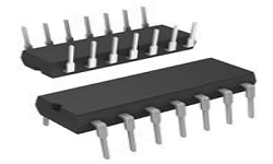
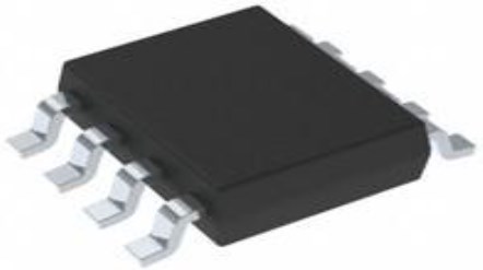
3 Bit Complementary Pair Plus Inverter -40°C~85°C Specialty Logic IC 4000B Series 4007 14 Pin 3V~15V 14-SOIC (0.154, 3.90mm Width)


3 Bit Complementary Pair Plus Inverter -40°C~85°C Specialty Logic IC 4000B Series 4007 14 Pin 3V~15V 14-SOIC (0.154, 3.90mm Width)
CD4007 is a dual complementary pair plus inverter. This article is going to explain the pin, features, applications, datasheet, and more details about the CD4007 inverter.

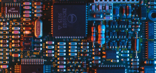
CMOS Inverter using CD4007 in a laboratory setting.
What is CD4007?
The CD4007 is made up of three pairs of N - and P-channel enhancement mode MOS transistors that can be used in series or shunt applications. The IC works in a variety of environments and can interact with CMOS, N MOS, and TTL devices directly. The IC is suitable for a wide range of applications, including low thermal dissipation and noise immunity. The voltages at all pins must be kept between VSS and VDD at 0.3V at all times to ensure proper operation. Clamping diodes at VD and VSS provide static protection for all inputs.
CD4007 Pinout


CD4007 Pinout
| Pin No | Pin Name | Description |
| 1 | 2Dp | The drain of p Channel 2 |
| 2 | 2Sp | Source of p Channel 2 |
| 3 | 2A | Input Channel 2 |
| 4 | 2Sn | Source of n Channel 2 |
| 5 | 2Dn | The drain of n Channel 2 |
| 6 | 1A | Input Channel 1 |
| 7 | VSS | Source Supply |
| 8 | 1Dn | The drain of n Channel 1 |
| 9 | 3Sn | Source of n Channel 3 |
| 10 | 3A | Input Channel 3 |
| 11 | 3Sp | Source of p Channel 3 |
| 12 | 3Y | output |
| 13 | 1Dp | The drain of p Channel 1 |
| 14 | VDD | Drain Supply |
CD4007 CAD Model

CD4007 Footprint

CD4007 3D Model
Specifications
- TypeParameter
- Mount
In electronic components, the term "Mount" typically refers to the method or process of physically attaching or fixing a component onto a circuit board or other electronic device. This can involve soldering, adhesive bonding, or other techniques to secure the component in place. The mounting process is crucial for ensuring proper electrical connections and mechanical stability within the electronic system. Different components may have specific mounting requirements based on their size, shape, and function, and manufacturers provide guidelines for proper mounting procedures to ensure optimal performance and reliability of the electronic device.
Surface Mount - Mounting Type
The "Mounting Type" in electronic components refers to the method used to attach or connect a component to a circuit board or other substrate, such as through-hole, surface-mount, or panel mount.
Surface Mount - Package / Case
refers to the protective housing that encases an electronic component, providing mechanical support, electrical connections, and thermal management.
14-SOIC (0.154, 3.90mm Width) - Number of Pins14
- Supplier Device Package
The parameter "Supplier Device Package" in electronic components refers to the physical packaging or housing of the component as provided by the supplier. It specifies the form factor, dimensions, and layout of the component, which are crucial for compatibility and integration into electronic circuits and systems. The supplier device package information typically includes details such as the package type (e.g., DIP, SOP, QFN), number of pins, pitch, and overall size, allowing engineers and designers to select the appropriate component for their specific application requirements. Understanding the supplier device package is essential for proper component selection, placement, and soldering during the manufacturing process to ensure optimal performance and reliability of the electronic system.
14-SOIC - Operating Temperature
The operating temperature is the range of ambient temperature within which a power supply, or any other electrical equipment, operate in. This ranges from a minimum operating temperature, to a peak or maximum operating temperature, outside which, the power supply may fail.
-40°C~85°C - Packaging
Semiconductor package is a carrier / shell used to contain and cover one or more semiconductor components or integrated circuits. The material of the shell can be metal, plastic, glass or ceramic.
Tube - Series
In electronic components, the "Series" refers to a group of products that share similar characteristics, designs, or functionalities, often produced by the same manufacturer. These components within a series typically have common specifications but may vary in terms of voltage, power, or packaging to meet different application needs. The series name helps identify and differentiate between various product lines within a manufacturer's catalog.
4000B - Published1999
- Part Status
Parts can have many statuses as they progress through the configuration, analysis, review, and approval stages.
Obsolete - Moisture Sensitivity Level (MSL)
Moisture Sensitivity Level (MSL) is a standardized rating that indicates the susceptibility of electronic components, particularly semiconductors, to moisture-induced damage during storage and the soldering process, defining the allowable exposure time to ambient conditions before they require special handling or baking to prevent failures
1 (Unlimited) - Max Operating Temperature
The Maximum Operating Temperature is the maximum body temperature at which the thermistor is designed to operate for extended periods of time with acceptable stability of its electrical characteristics.
85°C - Min Operating Temperature
The "Min Operating Temperature" parameter in electronic components refers to the lowest temperature at which the component is designed to operate effectively and reliably. This parameter is crucial for ensuring the proper functioning and longevity of the component, as operating below this temperature may lead to performance issues or even damage. Manufacturers specify the minimum operating temperature to provide guidance to users on the environmental conditions in which the component can safely operate. It is important to adhere to this parameter to prevent malfunctions and ensure the overall reliability of the electronic system.
-40°C - Supply Voltage
Supply voltage refers to the electrical potential difference provided to an electronic component or circuit. It is crucial for the proper operation of devices, as it powers their functions and determines performance characteristics. The supply voltage must be within specified limits to ensure reliability and prevent damage to components. Different electronic devices have specific supply voltage requirements, which can vary widely depending on their design and intended application.
3V~15V - Base Part Number
The "Base Part Number" (BPN) in electronic components serves a similar purpose to the "Base Product Number." It refers to the primary identifier for a component that captures the essential characteristics shared by a group of similar components. The BPN provides a fundamental way to reference a family or series of components without specifying all the variations and specific details.
4007 - Polarity
In electronic components, polarity refers to the orientation or direction in which the component must be connected in a circuit to function properly. Components such as diodes, capacitors, and LEDs have polarity markings to indicate which terminal should be connected to the positive or negative side of the circuit. Connecting a component with incorrect polarity can lead to malfunction or damage. It is important to pay attention to polarity markings and follow the manufacturer's instructions to ensure proper operation of electronic components.
Inverting - Number of Circuits2
- Max Supply Voltage
In general, the absolute maximum common-mode voltage is VEE-0.3V and VCC+0.3V, but for products without a protection element at the VCC side, voltages up to the absolute maximum rated supply voltage (i.e. VEE+36V) can be supplied, regardless of supply voltage.
15V - Min Supply Voltage
The minimum supply voltage (V min ) is explored for sequential logic circuits by statistically simulating the impact of within-die process variations and gate-dielectric soft breakdown on data retention and hold time.
3V - Number of Bits3
- Propagation Delay
the flight time of packets over the transmission link and is limited by the speed of light.
50 ns - Logic Function
In electronic components, the term "Logic Function" refers to the specific operation or behavior of a component based on its input signals. It describes how the component processes the input signals to produce the desired output. Logic functions are fundamental to digital circuits and are used to perform logical operations such as AND, OR, NOT, and XOR.Each electronic component, such as logic gates or flip-flops, is designed to perform a specific logic function based on its internal circuitry. By understanding the logic function of a component, engineers can design and analyze complex digital systems to ensure proper functionality and performance. Different logic functions can be combined to create more complex operations, allowing for the creation of sophisticated digital devices and systems.
Inverter - Logic Type
Logic Type in electronic components refers to the classification of circuits based on the logical operations they perform. It includes types such as AND, OR, NOT, NAND, NOR, XOR, and XNOR, each defining the relationship between binary inputs and outputs. The logic type determines how the inputs affect the output state based on specific rules of Boolean algebra. This classification is crucial for designing digital circuits and systems, enabling engineers to select appropriate components for desired functionalities.
Complementary Pair Plus Inverter - Number of Input Lines3
- Number of Output Lines3
- RoHS Status
RoHS means “Restriction of Certain Hazardous Substances” in the “Hazardous Substances Directive” in electrical and electronic equipment.
RoHS Compliant - Lead Free
Lead Free is a term used to describe electronic components that do not contain lead as part of their composition. Lead is a toxic material that can have harmful effects on human health and the environment, so the electronics industry has been moving towards lead-free components to reduce these risks. Lead-free components are typically made using alternative materials such as silver, copper, and tin. Manufacturers must comply with regulations such as the Restriction of Hazardous Substances (RoHS) directive to ensure that their products are lead-free and environmentally friendly.
Lead Free
CD4007 Features
Wide supply voltage range: 3.0V to 15V
High noise immunity: 0.45 VCC (Typ.)
100% tested for quiescent current at 20V
Standardized symmetrical output characteristics
CD4007 Applications
Sharpers
Inverters
Threshold detectors
Linear amplifiers
Crystal oscillators
Using the CD4007 transistor array to make inverters
One CD4007 package can be used to make up to three separate inverters. The first one is the simplest to set up, as illustrated below, by connecting pins 8 and 13 as the inverter output. The input will be on pin 6. Make sure pin14 VDD is connected to power and pin 7 VSS is connected to the ground.

CD4007 Inverter
Pin 2 is connected to VDD. pin 4 to VSS. Pins 1 and 5 are connected as the output, and pin 3 is used as the input in the second inverter. Pin11 is connected to VDD, pin 9 to VSS, pin 12 is the output, and pin 10 is the input in the third inverter.
CD4007 Dimensions


CD4007 Dimensions
CD4007 Manufacturer
ON Semiconductor (Nasdaq: ON) is driving energy-efficient innovations, empowering customers to reduce global energy use. The company offers a comprehensive portfolio of energy-efficient power and signal management, logic, discrete and custom solutions to help design engineers solve their unique design challenges in automotive, communications, computing, consumer, industrial, LED lighting, medical, military/aerospace, and power supply applications. ON Semiconductor operates a responsive, reliable, world-class supply chain and quality program, and a network of manufacturing facilities, sales offices, and design centers in key markets throughout North America, Europe, and the Asia Pacific regions.
Parts with Similar Specs
- ImagePart NumberManufacturerPackage / CaseNumber of PinsLogic FunctionNumber of CircuitsNumber of Output LinesPropagation DelayMin Supply VoltageSupply VoltageView Compare
![CD4007CM]()
CD4007CM
14-SOIC (0.154, 3.90mm Width)
14
Inverter
2
3
50 ns
3 V
3V ~ 15V
![MC14007UBD]()
14-SOIC (0.154, 3.90mm Width)
14
-
-
-
18 ns
-
5 V
![SN74HCT04DR]()
14-SOIC (0.154, 3.90mm Width)
14
Inverter
-
-
55 ns
3 V
3V ~ 18V


Datasheet PDF
- Datasheets :
- ReachStatement :
What can be CD4007 used for?
The CD4007 is a very versatile IC with many uses. For example, a single CD4007 can be used to make a chain of 3 inverters, an inverter plus two transmission gates, or a complex logic gate. Inverters and transmission gates are particularly useful for building D flip-flops.
What is the voltage of CD4007?
The IC offers a wide variety of applications such as low thermal dissipation and high noise immunity. For proper operation, the voltages at all pins must be constrained to be between VSS at 0.3V and VDD at 0.3V at all times.
What is the circuit of CD4007?
The CD4007 is a monolithic integrated circuit fabricated in Metal Oxide Semiconductor technology available in DIP and SOP packages. The CD4007 (HCF4007UB) type is comprised of three n-channel and three p-channel enhancement type MOS transistors.
![LMR® -400 Coaxial Cables (RF) 50Ohms[Video]:Datasheet, Features, and Applications](https://res.utmel.com/Images/Article/fee4ddfa-7969-484f-ac95-2f6daa997670.png) LMR® -400 Coaxial Cables (RF) 50Ohms[Video]:Datasheet, Features, and Applications
LMR® -400 Coaxial Cables (RF) 50Ohms[Video]:Datasheet, Features, and Applications12 June 20245165
 ADM2587EBRWZ Transceiver, RS-422/RS-485 20-SOIC, Signal and Power Isolated
09 February 20223405
 SN74LS32N Positive-OR Gate: Features, Applications and Datasheet
16 October 20233309
 Guide to Choosing Ethernet Transceivers for Industrial Networks
09 June 2025244
 TXS0108ERGYR Translators: Features, Applications and Datasheet
19 December 2023603
 LM53601LQDSXTQ1: Pinout, Automotive, Step-Down, Converter
14 February 2022327
 DS1820 Digital Thermometer: Pinout, Datasheet and Comparison
04 August 20216502
 STM32F205ZGT6TR Microcontroller Datasheet Overview
29 February 2024247
 FPGA vs. Microcontroller Technology: Similarities and Differences
13 March 20245668
 How to Find the Ideal Voltage Reference for Your Application
11 July 20251254
 What is PLL(Phase Locked Loop)?
29 November 20216379
 Analyzing Temperature Parameters of Si, SiC and GaN Power Devices
09 September 20231451
 VSC Light Meaning, Causes, and Step-by-Step Diagnostics
19 May 2026387
 Utmel Attends the PCIM Europe 2023– Excelling in Power Electronics
20 June 20236819
 ICinsights:MCUs Will Continue to Rise in Price
30 March 20225897
 A Comprehensive Guide to FPGA Development Boards
11 September 202519269
ON Semiconductor
In Stock
United States
China
Canada
Japan
Russia
Germany
United Kingdom
Singapore
Italy
Hong Kong(China)
Taiwan(China)
France
Korea
Mexico
Netherlands
Malaysia
Austria
Spain
Switzerland
Poland
Thailand
Vietnam
India
United Arab Emirates
Afghanistan
Åland Islands
Albania
Algeria
American Samoa
Andorra
Angola
Anguilla
Antigua & Barbuda
Argentina
Armenia
Aruba
Australia
Azerbaijan
Bahamas
Bahrain
Bangladesh
Barbados
Belarus
Belgium
Belize
Benin
Bermuda
Bhutan
Bolivia
Bonaire, Sint Eustatius and Saba
Bosnia & Herzegovina
Botswana
Brazil
British Indian Ocean Territory
British Virgin Islands
Brunei
Bulgaria
Burkina Faso
Burundi
Cabo Verde
Cambodia
Cameroon
Cayman Islands
Central African Republic
Chad
Chile
Christmas Island
Cocos (Keeling) Islands
Colombia
Comoros
Congo
Congo (DRC)
Cook Islands
Costa Rica
Côte d’Ivoire
Croatia
Cuba
Curaçao
Cyprus
Czechia
Denmark
Djibouti
Dominica
Dominican Republic
Ecuador
Egypt
El Salvador
Equatorial Guinea
Eritrea
Estonia
Eswatini
Ethiopia
Falkland Islands
Faroe Islands
Fiji
Finland
French Guiana
French Polynesia
Gabon
Gambia
Georgia
Ghana
Gibraltar
Greece
Greenland
Grenada
Guadeloupe
Guam
Guatemala
Guernsey
Guinea
Guinea-Bissau
Guyana
Haiti
Honduras
Hungary
Iceland
Indonesia
Iran
Iraq
Ireland
Isle of Man
Israel
Jamaica
Jersey
Jordan
Kazakhstan
Kenya
Kiribati
Kosovo
Kuwait
Kyrgyzstan
Laos
Latvia
Lebanon
Lesotho
Liberia
Libya
Liechtenstein
Lithuania
Luxembourg
Macao(China)
Madagascar
Malawi
Maldives
Mali
Malta
Marshall Islands
Martinique
Mauritania
Mauritius
Mayotte
Micronesia
Moldova
Monaco
Mongolia
Montenegro
Montserrat
Morocco
Mozambique
Myanmar
Namibia
Nauru
Nepal
New Caledonia
New Zealand
Nicaragua
Niger
Nigeria
Niue
Norfolk Island
North Korea
North Macedonia
Northern Mariana Islands
Norway
Oman
Pakistan
Palau
Palestinian Authority
Panama
Papua New Guinea
Paraguay
Peru
Philippines
Pitcairn Islands
Portugal
Puerto Rico
Qatar
Réunion
Romania
Rwanda
Samoa
San Marino
São Tomé & Príncipe
Saudi Arabia
Senegal
Serbia
Seychelles
Sierra Leone
Sint Maarten
Slovakia
Slovenia
Solomon Islands
Somalia
South Africa
South Sudan
Sri Lanka
St Helena, Ascension, Tristan da Cunha
St. Barthélemy
St. Kitts & Nevis
St. Lucia
St. Martin
St. Pierre & Miquelon
St. Vincent & Grenadines
Sudan
Suriname
Svalbard & Jan Mayen
Sweden
Syria
Tajikistan
Tanzania
Timor-Leste
Togo
Tokelau
Tonga
Trinidad & Tobago
Tunisia
Turkey
Turkmenistan
Turks & Caicos Islands
Tuvalu
U.S. Outlying Islands
U.S. Virgin Islands
Uganda
Ukraine
Uruguay
Uzbekistan
Vanuatu
Vatican City
Venezuela
Wallis & Futuna
Yemen
Zambia
Zimbabwe
![MC14490DWG]() MC14490DWG
MC14490DWGON Semiconductor
![MC14490DWR2G]() MC14490DWR2G
MC14490DWR2GON Semiconductor
![MC10EL16DR2G]() MC10EL16DR2G
MC10EL16DR2GON Semiconductor
![MC100EL16DR2G]() MC100EL16DR2G
MC100EL16DR2GON Semiconductor
![NB4N527SMNG]() NB4N527SMNG
NB4N527SMNGON Semiconductor
![MC100LVEL16DR2G]() MC100LVEL16DR2G
MC100LVEL16DR2GON Semiconductor
![NB7VQ1006MMNTXG]() NB7VQ1006MMNTXG
NB7VQ1006MMNTXGON Semiconductor
![MC100LVEP16DTG]() MC100LVEP16DTG
MC100LVEP16DTGON Semiconductor
![74VHC161284MTDX]() 74VHC161284MTDX
74VHC161284MTDXON Semiconductor
![MC100EL16DG]() MC100EL16DG
MC100EL16DGON Semiconductor


