
BTS7960B Motor Driver: Datasheet PDF, Pinout, Application Circuit


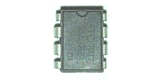
IC NOVALITHIC 1/2 BRIDGE TO263-7
The BTS7960B is a fully integrated high current half-bridge motor driver IC. This post will unlock more details about BTS7960B, including its datasheet, pinout, features and more about BTS7960B. Welcome your RFQ!

How to work with BTS7960 motor driver and Arduino
BTS7960B Pinout

BTS7960B Pinout
Pin Number | Pin Name | Description |
1 | GND | Ground |
2 | IN | Input defines whether high- or low side switch is activated |
3 | INH | Inhibit, (when set to low device goes into sleep mode ) |
4 | OUT | The power output of the bridge |
5 | SR | Slew Rate, (the slew rate of the power switches can be adjusted by connecting a resistor between SR and GND) |
6 | IS | Current Sense and Diagnosis |
7 | VS | Power Supply |
8 | OUT | The power output of the bridge |
BTS7960B CAD Model
Symbol

BTS7960B Symbol
Footprint

BTS7960BFootprint
3D Model

BTS7960B 3D Model
BTS7960B Description
The BTS7960B is a fully integrated high current half bridge for motor drive applications. It is part of the NovalithICTM family containing one p-channel high side MOSFET and one n-channel low-side MOSFET with an integrated driver IC in one package. Due to the p-channel high side switch, the need for a charge pump is eliminated thus minimizing EMI. Interfacing to a microcontroller is made easy by the integrated driver IC which features logic level inputs, diagnosis with current sense, slew rate adjustment, dead time generation and protection against overtemperature, overvoltage, Undervoltage, overcurrent and short circuit.
The BTS7960B provides a cost-optimized solution for protected high current PWM motor drives with very low board space consumption.
BTS7960B Features
• Path resistance of typ. 16 mΩ @ 25 °C
• Low quiescent current of typ. 7 µA @ 25 °C
• PWM capability of up to 25 kHz combined with active freewheeling
• Switched mode current limitation for reduced power dissipation in overcurrent
• Current limitation level of 43 A typ.
• Status flag diagnosis with current sense capability
• Overtemperature shut down with latch behaviour
• Overvoltage lockout
• Undervoltage shut down
• Driver circuit with logic level inputs
• Adjustable slew rates for optimized EMI
BTS7960B Application
Used to drive high current Motors using Digital Circuits
Can be used to drive Stepper motors
High current LED’s can be driven
Relay Driver Module (Latching Relay is possible)
High Power and High Amp DC Motors and Servo Motors
BTS7960B Alternatives
The alternatives for BTS7960B:
L293D
DRV8833
MX1508
TB6612FNG
L298
How to Use BTS7960B
The BTC7960B is a high-capacity motor driver integrated circuit. It is mostly used to drive motors, as the name implies. Because it is a half-bridge motor driver IC, you will need two of these ICs to rotate the DC motor bidirectionally. The operating voltage of this device is greater than 40V, so it can drive pretty beefy motors. The operating current of this device is 600mA, so it can be driven by a microcontroller or a 555 timer IC to generate a PWM signal that can control the speed of the motor.

BTS7960B Application Circuit
As you can see in the diagram above, using this IC is fairly simple. The datasheet for the device attached below shows the schematic shown above, the circuit and connections are fairly simple, and the two motor drivers in an H-bridge configuration are used to drive a motor so that the motor can rotate in both reverse and forward directions. As previously stated, the microcontroller is used to provide a PWM signal that can be used to control the motor's speed.
The motor can be rotated either clockwise or any clockwise by alternating the driving direction; this is a fairly popular IC, and if you are testing this IC for your design, there are prebuilt modules available in the market that you can use for testing purposes; those modular are compatible with Arduino, and one of them is shown below.

Module
Specifications
- TypeParameter
- Mounting Type
The "Mounting Type" in electronic components refers to the method used to attach or connect a component to a circuit board or other substrate, such as through-hole, surface-mount, or panel mount.
Surface Mount - Package / Case
refers to the protective housing that encases an electronic component, providing mechanical support, electrical connections, and thermal management.
TO-263-8, D2Pak (7 Leads + Tab), TO-263CA - Surface Mount
having leads that are designed to be soldered on the side of a circuit board that the body of the component is mounted on.
YES - Number of Pins7
- Operating Temperature
The operating temperature is the range of ambient temperature within which a power supply, or any other electrical equipment, operate in. This ranges from a minimum operating temperature, to a peak or maximum operating temperature, outside which, the power supply may fail.
-40°C~150°C TJ - Packaging
Semiconductor package is a carrier / shell used to contain and cover one or more semiconductor components or integrated circuits. The material of the shell can be metal, plastic, glass or ceramic.
Tape & Reel (TR) - Series
In electronic components, the "Series" refers to a group of products that share similar characteristics, designs, or functionalities, often produced by the same manufacturer. These components within a series typically have common specifications but may vary in terms of voltage, power, or packaging to meet different application needs. The series name helps identify and differentiate between various product lines within a manufacturer's catalog.
NovalithIC™ - Published2005
- Part Status
Parts can have many statuses as they progress through the configuration, analysis, review, and approval stages.
Obsolete - Moisture Sensitivity Level (MSL)
Moisture Sensitivity Level (MSL) is a standardized rating that indicates the susceptibility of electronic components, particularly semiconductors, to moisture-induced damage during storage and the soldering process, defining the allowable exposure time to ambient conditions before they require special handling or baking to prevent failures
1 (Unlimited) - Number of Terminations7
- ECCN Code
An ECCN (Export Control Classification Number) is an alphanumeric code used by the U.S. Bureau of Industry and Security to identify and categorize electronic components and other dual-use items that may require an export license based on their technical characteristics and potential for military use.
EAR99 - Applications
The parameter "Applications" in electronic components refers to the specific uses or functions for which a component is designed. It encompasses various fields such as consumer electronics, industrial automation, telecommunications, automotive, and medical devices. Understanding the applications helps in selecting the right components for a particular design based on performance, reliability, and compatibility requirements. This parameter also guides manufacturers in targeting their products to relevant markets and customer needs.
DC Motors, General Purpose - HTS Code
HTS (Harmonized Tariff Schedule) codes are product classification codes between 8-1 digits. The first six digits are an HS code, and the countries of import assign the subsequent digits to provide additional classification. U.S. HTS codes are 1 digits and are administered by the U.S. International Trade Commission.
8542.39.00.01 - Voltage - Supply
Voltage - Supply refers to the range of voltage levels that an electronic component or circuit is designed to operate with. It indicates the minimum and maximum supply voltage that can be applied for the device to function properly. Providing supply voltages outside this range can lead to malfunction, damage, or reduced performance. This parameter is critical for ensuring compatibility between different components in a circuit.
5.5V~27.5V - Terminal Position
In electronic components, the term "Terminal Position" refers to the physical location of the connection points on the component where external electrical connections can be made. These connection points, known as terminals, are typically used to attach wires, leads, or other components to the main body of the electronic component. The terminal position is important for ensuring proper connectivity and functionality of the component within a circuit. It is often specified in technical datasheets or component specifications to help designers and engineers understand how to properly integrate the component into their circuit designs.
DUAL - Terminal Form
Occurring at or forming the end of a series, succession, or the like; closing; concluding.
GULL WING - Peak Reflow Temperature (Cel)
Peak Reflow Temperature (Cel) is a parameter that specifies the maximum temperature at which an electronic component can be exposed during the reflow soldering process. Reflow soldering is a common method used to attach electronic components to a circuit board. The Peak Reflow Temperature is crucial because it ensures that the component is not damaged or degraded during the soldering process. Exceeding the specified Peak Reflow Temperature can lead to issues such as component failure, reduced performance, or even permanent damage to the component. It is important for manufacturers and assemblers to adhere to the recommended Peak Reflow Temperature to ensure the reliability and functionality of the electronic components.
NOT SPECIFIED - Number of Functions1
- Supply Voltage
Supply voltage refers to the electrical potential difference provided to an electronic component or circuit. It is crucial for the proper operation of devices, as it powers their functions and determines performance characteristics. The supply voltage must be within specified limits to ensure reliability and prevent damage to components. Different electronic devices have specific supply voltage requirements, which can vary widely depending on their design and intended application.
8V - Reach Compliance Code
Reach Compliance Code refers to a designation indicating that electronic components meet the requirements set by the Registration, Evaluation, Authorization, and Restriction of Chemicals (REACH) regulation in the European Union. It signifies that the manufacturer has assessed and managed the chemical substances within the components to ensure safety and environmental protection. This code is vital for compliance with regulations aimed at minimizing risks associated with hazardous substances in electronic products.
unknown - Time@Peak Reflow Temperature-Max (s)
Time@Peak Reflow Temperature-Max (s) refers to the maximum duration that an electronic component can be exposed to the peak reflow temperature during the soldering process, which is crucial for ensuring reliable solder joint formation without damaging the component.
NOT SPECIFIED - Base Part Number
The "Base Part Number" (BPN) in electronic components serves a similar purpose to the "Base Product Number." It refers to the primary identifier for a component that captures the essential characteristics shared by a group of similar components. The BPN provides a fundamental way to reference a family or series of components without specifying all the variations and specific details.
BTS7960 - Pin Count
a count of all of the component leads (or pins)
4 - Qualification Status
An indicator of formal certification of qualifications.
Not Qualified - Max Output Current
The maximum current that can be supplied to the load.
60A - Interface
In electronic components, the term "Interface" refers to the point at which two different systems, devices, or components connect and interact with each other. It can involve physical connections such as ports, connectors, or cables, as well as communication protocols and standards that facilitate the exchange of data or signals between the connected entities. The interface serves as a bridge that enables seamless communication and interoperability between different parts of a system or between different systems altogether. Designing a reliable and efficient interface is crucial in ensuring proper functionality and performance of electronic components and systems.
Logic - Output Configuration
Output Configuration in electronic components refers to the arrangement or setup of the output pins or terminals of a device. It defines how the output signals are structured and how they interact with external circuits or devices. The output configuration can determine the functionality and compatibility of the component in a circuit design. Common types of output configurations include single-ended, differential, open-drain, and push-pull configurations, each serving different purposes and applications in electronic systems. Understanding the output configuration of a component is crucial for proper integration and operation within a circuit.
Half Bridge - Quiescent Current
The quiescent current is defined as the current level in the amplifier when it is producing an output of zero.
7μA - Halogen Free
The term "Halogen Free" in electronic components refers to a specific characteristic of the materials used in the manufacturing of the component. Halogens are a group of elements that include fluorine, chlorine, bromine, iodine, and astatine. These elements are commonly used in flame retardants and other materials in electronics. However, the presence of halogens can pose environmental and health risks when the components are disposed of or recycled.Therefore, electronic components labeled as "Halogen Free" are manufactured without the use of halogenated materials. This designation indicates that the components do not contain any halogens, making them safer for the environment and human health. Halogen-free components are becoming increasingly popular in the electronics industry due to the growing awareness of environmental concerns and regulations regarding hazardous substances in electronic products.
Not Halogen Free - Output Current per Channel
Output Current per Channel is a specification commonly found in electronic components such as amplifiers, audio interfaces, and power supplies. It refers to the maximum amount of electrical current that can be delivered by each individual output channel of the component. This parameter is important because it determines the capacity of the component to drive connected devices or loads. A higher output current per channel means the component can deliver more power to connected devices, while a lower output current may limit the performance or functionality of the component in certain applications. It is crucial to consider the output current per channel when selecting electronic components to ensure they can meet the power requirements of the intended system or setup.
40A - Voltage - Load
Voltage - Load refers to the voltage across a load component in an electronic circuit when it is connected and operational. It represents the electrical potential difference that drives current through the load, which can be a resistor, motor, or other devices that consume electrical power. The voltage - load relationship is crucial for determining how much power the load will utilize and how it will affect the overall circuit performance. Properly managing voltage - load is essential for ensuring devices operate efficiently and safely within their specified limits.
5.5V~27.5V - Fault Protection
Protection against electric shock under. single fault conditions.
Current Limiting, Over Temperature, Short Circuit, UVLO - Turn On Time
The time that it takes a gate circuit to allow a current to reach its full value.
25.4 μs - Output Peak Current Limit-Nom
Output Peak Current Limit-Nom is a parameter in electronic components that specifies the maximum current that can be delivered by the output under normal operating conditions. This limit is typically set to protect the component from damage due to excessive current flow. It ensures that the component operates within its safe operating limits and prevents overheating or other potential issues. Designers and engineers use this parameter to ensure proper functioning and reliability of the electronic system in which the component is used.
62A - Rds On (Typ)
The parameter "Rds On (Typ)" in electronic components refers to the typical on-state resistance of a MOSFET (Metal-Oxide-Semiconductor Field-Effect Transistor) when it is fully conducting. This parameter indicates the resistance encountered by the current flowing through the MOSFET when it is in the on-state, which affects the power dissipation and efficiency of the component. A lower Rds On value indicates better conduction and lower power loss in the MOSFET. Designers often consider this parameter when selecting components for applications where minimizing power loss and maximizing efficiency are critical factors.
9m Ω LS, 7m Ω HS - Turn Off Time
Turn Off Time is a parameter in electronic components, particularly in devices like transistors and diodes. It refers to the time taken for the component to switch from an ON state to an OFF state when a control signal is applied. This parameter is crucial in determining the speed and efficiency of the component's operation. A shorter turn off time indicates faster switching speeds, which is important in applications where rapid switching is required, such as in power electronics and digital circuits. Manufacturers provide this specification in datasheets to help engineers and designers select the right components for their specific requirements.
16 μs - Built-in Protections
Built-in protections in electronic components refer to the safety features and mechanisms that are integrated into the component to prevent damage or malfunction in various situations. These protections are designed to safeguard the component from overvoltage, overcurrent, overheating, short circuits, and other potential hazards that could occur during operation. By having built-in protections, electronic components can operate more reliably and safely, extending their lifespan and reducing the risk of failure. These protections are essential for ensuring the overall performance and longevity of electronic devices and systems.
TRANSIENT; OVER CURRENT; OVER VOLTAGE; THERMAL; UNDER VOLTAGE - Output Current Flow Direction
Output Current Flow Direction refers to the orientation of current flowing out of a component or circuit. It indicates whether the current is being sourced from the component or sent to another component in the circuit. This parameter is crucial for understanding how electronic components interact within a circuit and ensures correct connectivity and functionality in circuit design. The direction can affect the operation and performance of the overall system.
SOURCE SINK - Load Type
Load Type in electronic components refers to the manner in which a load interacts with a circuit. It can be classified into different categories such as resistive, inductive, and capacitive loads. Each load type affects the circuit's performance, including voltage and current behavior, power factor, and overall efficiency. Understanding the load type is essential for optimizing circuit design and ensuring compatibility between components.
Inductive - Features
In the context of electronic components, the term "Features" typically refers to the specific characteristics or functionalities that a particular component offers. These features can vary depending on the type of component and its intended use. For example, a microcontroller may have features such as built-in memory, analog-to-digital converters, and communication interfaces like UART or SPI.When evaluating electronic components, understanding their features is crucial in determining whether they meet the requirements of a particular project or application. Engineers and designers often look at features such as operating voltage, speed, power consumption, and communication protocols to ensure compatibility and optimal performance.In summary, the "Features" parameter in electronic components describes the unique attributes and capabilities that differentiate one component from another, helping users make informed decisions when selecting components for their electronic designs.
Latch Function, Slew Rate Controlled, Status Flag - Length9.9mm
- Width9.2mm
- RoHS Status
RoHS means “Restriction of Certain Hazardous Substances” in the “Hazardous Substances Directive” in electrical and electronic equipment.
Non-RoHS Compliant - Lead Free
Lead Free is a term used to describe electronic components that do not contain lead as part of their composition. Lead is a toxic material that can have harmful effects on human health and the environment, so the electronics industry has been moving towards lead-free components to reduce these risks. Lead-free components are typically made using alternative materials such as silver, copper, and tin. Manufacturers must comply with regulations such as the Restriction of Hazardous Substances (RoHS) directive to ensure that their products are lead-free and environmentally friendly.
Contains Lead
BTS7960B Dimensions

BTS7960B Manufacturer
On April 1st, 1999, Siemens Semiconductors became Infineon Technologies. A dynamic more flexible company geared towards success in the competitive, ever-changing world of microelectronics. Infineon is a leading global designer, manufacturer and supplier of a broad range of semiconductors used in various microelectronic applications. Infineon's product portfolio consists of logic products, including digital, mixed-signal, and analogue integrated circuits, as well as discrete semiconductor products.
Datasheet PDF
- Datasheets :
- Other Related Documents :
- PCN Obsolescence/ EOL :
- ConflictMineralStatement :
Trend Analysis
What is H-Bridge with MOSFETs?
The drive circuitry for an H-Bridge is basically the electronics that sits between the PWM (and potentially other) digital control inputs and the MOSFET gates. It has two major purposes: Translate the input voltages to suitable levels to drive the gates.
What is BTS7960B motor driver?
The BTS7960B is a high-current full-bridge motor driver module. ... Maximum allowable current: 43 A. PWM capability: up to 25 kHz. Two PWM output pins for speed control in direct and reverse directions. Two EN output pins to control motors.
What is the difference between a motor driver and a motor controller?
Motor Driver VS Motor Controller
The main difference between a motor controller and a motor driver is, the motor controller is responsible for the controlling speed, torque, the direction of the motor whereas a motor driver is responsible to provide enough electrical power to the motor as per requirement.
 Audio Amplifier IC LM386:Where/How to use?
05 May 202210722
 TDA7498E Audio Amplifier: Block Diagram, Datasheet, and Test Circuit
13 July 202119630
![FDG6335N N-Channel MOSFET: Diagram, Pinout, and Datasheet [Video&FAQ]](https://res.utmel.com/Images/Article/ed8c0389-8d09-46cf-91fb-43c5dd0cf724.png) FDG6335N N-Channel MOSFET: Diagram, Pinout, and Datasheet [Video&FAQ]
FDG6335N N-Channel MOSFET: Diagram, Pinout, and Datasheet [Video&FAQ]28 April 20221903
 PCM1794A Converter: Datasheet, Alternatives, Application Circuit
30 September 20212335
 A Deep Dive into the S-814A25AMC-BCPT2G Linear Voltage Regulator
07 March 2024426
 A Comprehensive Guide to LTZ1000ACH Voltage Reference IC
06 March 2024443
 Difference between RS232 RS422 and RS485
08 March 20224227
 MSP430FG4619IPZ Mixed Signal Microcontroller: Comprehensive Technical Overview
29 February 2024113
 Understanding Adapter Cards in Modern Computers
05 July 20252364
 What is Semiconductor Package?
06 December 202111325
 Introduction to FinFET
18 March 202128525
 What is the Difference between DCS and PLC?
28 June 20224549
 What is a Multimeter?
20 December 20216216
 What is G.654E Fiber?
24 May 20225359
 Introduction to DC Amplifier
07 November 202517013
 Analysis and Solutions of Common Causes of Serial Port Lost Data
15 August 20224463
Infineon Technologies
In Stock: 21368
United States
China
Canada
Japan
Russia
Germany
United Kingdom
Singapore
Italy
Hong Kong(China)
Taiwan(China)
France
Korea
Mexico
Netherlands
Malaysia
Austria
Spain
Switzerland
Poland
Thailand
Vietnam
India
United Arab Emirates
Afghanistan
Åland Islands
Albania
Algeria
American Samoa
Andorra
Angola
Anguilla
Antigua & Barbuda
Argentina
Armenia
Aruba
Australia
Azerbaijan
Bahamas
Bahrain
Bangladesh
Barbados
Belarus
Belgium
Belize
Benin
Bermuda
Bhutan
Bolivia
Bonaire, Sint Eustatius and Saba
Bosnia & Herzegovina
Botswana
Brazil
British Indian Ocean Territory
British Virgin Islands
Brunei
Bulgaria
Burkina Faso
Burundi
Cabo Verde
Cambodia
Cameroon
Cayman Islands
Central African Republic
Chad
Chile
Christmas Island
Cocos (Keeling) Islands
Colombia
Comoros
Congo
Congo (DRC)
Cook Islands
Costa Rica
Côte d’Ivoire
Croatia
Cuba
Curaçao
Cyprus
Czechia
Denmark
Djibouti
Dominica
Dominican Republic
Ecuador
Egypt
El Salvador
Equatorial Guinea
Eritrea
Estonia
Eswatini
Ethiopia
Falkland Islands
Faroe Islands
Fiji
Finland
French Guiana
French Polynesia
Gabon
Gambia
Georgia
Ghana
Gibraltar
Greece
Greenland
Grenada
Guadeloupe
Guam
Guatemala
Guernsey
Guinea
Guinea-Bissau
Guyana
Haiti
Honduras
Hungary
Iceland
Indonesia
Iran
Iraq
Ireland
Isle of Man
Israel
Jamaica
Jersey
Jordan
Kazakhstan
Kenya
Kiribati
Kosovo
Kuwait
Kyrgyzstan
Laos
Latvia
Lebanon
Lesotho
Liberia
Libya
Liechtenstein
Lithuania
Luxembourg
Macao(China)
Madagascar
Malawi
Maldives
Mali
Malta
Marshall Islands
Martinique
Mauritania
Mauritius
Mayotte
Micronesia
Moldova
Monaco
Mongolia
Montenegro
Montserrat
Morocco
Mozambique
Myanmar
Namibia
Nauru
Nepal
New Caledonia
New Zealand
Nicaragua
Niger
Nigeria
Niue
Norfolk Island
North Korea
North Macedonia
Northern Mariana Islands
Norway
Oman
Pakistan
Palau
Palestinian Authority
Panama
Papua New Guinea
Paraguay
Peru
Philippines
Pitcairn Islands
Portugal
Puerto Rico
Qatar
Réunion
Romania
Rwanda
Samoa
San Marino
São Tomé & Príncipe
Saudi Arabia
Senegal
Serbia
Seychelles
Sierra Leone
Sint Maarten
Slovakia
Slovenia
Solomon Islands
Somalia
South Africa
South Sudan
Sri Lanka
St Helena, Ascension, Tristan da Cunha
St. Barthélemy
St. Kitts & Nevis
St. Lucia
St. Martin
St. Pierre & Miquelon
St. Vincent & Grenadines
Sudan
Suriname
Svalbard & Jan Mayen
Sweden
Syria
Tajikistan
Tanzania
Timor-Leste
Togo
Tokelau
Tonga
Trinidad & Tobago
Tunisia
Turkey
Turkmenistan
Turks & Caicos Islands
Tuvalu
U.S. Outlying Islands
U.S. Virgin Islands
Uganda
Ukraine
Uruguay
Uzbekistan
Vanuatu
Vatican City
Venezuela
Wallis & Futuna
Yemen
Zambia
Zimbabwe
![BTN8962TAAUMA1]() BTN8962TAAUMA1
BTN8962TAAUMA1Infineon Technologies
![IFX9201SGAUMA1]() IFX9201SGAUMA1
IFX9201SGAUMA1Infineon Technologies
![BTN8982TAAUMA1]() BTN8982TAAUMA1
BTN8982TAAUMA1Infineon Technologies
![TLE9201SGAUMA1]() TLE9201SGAUMA1
TLE9201SGAUMA1Infineon Technologies
![IR3551MTRPBF]() IR3551MTRPBF
IR3551MTRPBFInfineon Technologies
![BTM7710GXUMA1]() BTM7710GXUMA1
BTM7710GXUMA1Infineon Technologies
![TDA21240AUMA1]() TDA21240AUMA1
TDA21240AUMA1Infineon Technologies
![IR3553MTRPBF]() IR3553MTRPBF
IR3553MTRPBFInfineon Technologies
![BTN8960TAAUMA1]() BTN8960TAAUMA1
BTN8960TAAUMA1Infineon Technologies
![IR3555MTRPBF]() IR3555MTRPBF
IR3555MTRPBFInfineon Technologies


