
CD74HCT40103: High-Speed CMOS Logic 8-Stage Synchronous Down Counter

5V DUAL Counters & Dividers 74HCT Series 74HCT40103 16 Pins Down Positive Edge 16-SOIC (0.154, 3.90mm Width)
Unit Price: $0.720645
Ext Price: $0.72


5V DUAL Counters & Dividers 74HCT Series 74HCT40103 16 Pins Down Positive Edge 16-SOIC (0.154, 3.90mm Width)
The CD74HCT40103 is manufactured with high speed silicon gate technology and consist of an 8-stage synchronous down counter with a single output which is active when the internal count is zero. The 40103 contains a single 8-bit binary counter. Furthermore, Huge range of Semiconductors, Capacitors, Resistors and IcS in stock. Welcome RFQ.

3 bits Synchronous Up Down Counter (Designing, Circuit & Working), Digital Electronics
CD74HCT40103 Pinout
The following figure is the diagram of CD74HCT40103 pinout.

Pinout
CD74HCT40103 CAD Model
The followings are CD74HCT40103 Symbol, Footprint, and 3D Model.

PCB Symbol

PCB Footprint

3D Model
CD74HCT40103 Overview
The CD74HCT40103 is manufactured with high speed silicon gate technology and consist of an 8-stage synchronous down counter with a single output which is active when the internal count is zero. The 40103 contains a single 8-bit binary counter. Each has control inputs for enabling or disabling the clock, for clearing the counter to its maximum count, and for presetting the counter either synchronously or asynchronously. All control inputs are active-low logic.
This article provides you with a basic overview of the CD74HCT40103, including its pin descriptions, features and specifications, etc., to help you quickly understand what CD74HCT40103 is.
CD74HCT40103 Features
● Synchronous or Asynchronous Preset
● Cascadable in Synchronous or Ripple Mode
● Fanout (Over Temperature Range)
◆ Standard Outputs: 10 LSTTL Loads
◆ Bus Driver Outputs: 15 LSTTL Loads
● Wide Operating Temperature Range: ﹣55 ℃ to ﹢125 ℃
● Balanced Propagation Delay and Transition Times
● Significant Power Reduction Compared to LSTTL Logic ICs
● HC Types
◆ 2V to 6V Operation
◆ High Noise Immunity: NIL = 30%, NIH = 30% of VCC at VCC = 5V
● HCT Types
◆ 4.5V to 5.5V Operation
◆ Direct LSTTL Input Logic Compatibility, VIL= 0.8V (Max), VIH = 2V (Min)
◆ CMOS Input Compatibility, Il ≤ 1µA at VOL, VOH
Specifications
- TypeParameter
- Lifecycle Status
Lifecycle Status refers to the current stage of an electronic component in its product life cycle, indicating whether it is active, obsolete, or transitioning between these states. An active status means the component is in production and available for purchase. An obsolete status indicates that the component is no longer being manufactured or supported, and manufacturers typically provide a limited time frame for support. Understanding the lifecycle status is crucial for design engineers to ensure continuity and reliability in their projects.
ACTIVE (Last Updated: 2 days ago) - Factory Lead Time6 Weeks
- Contact Plating
Contact plating (finish) provides corrosion protection for base metals and optimizes the mechanical and electrical properties of the contact interfaces.
Gold - Mount
In electronic components, the term "Mount" typically refers to the method or process of physically attaching or fixing a component onto a circuit board or other electronic device. This can involve soldering, adhesive bonding, or other techniques to secure the component in place. The mounting process is crucial for ensuring proper electrical connections and mechanical stability within the electronic system. Different components may have specific mounting requirements based on their size, shape, and function, and manufacturers provide guidelines for proper mounting procedures to ensure optimal performance and reliability of the electronic device.
Surface Mount - Mounting Type
The "Mounting Type" in electronic components refers to the method used to attach or connect a component to a circuit board or other substrate, such as through-hole, surface-mount, or panel mount.
Surface Mount - Package / Case
refers to the protective housing that encases an electronic component, providing mechanical support, electrical connections, and thermal management.
16-SOIC (0.154, 3.90mm Width) - Number of Pins16
- Weight141.690917mg
- Clock-Edge Trigger TypePositive Edge
- Number of Elements1
- Operating Temperature
The operating temperature is the range of ambient temperature within which a power supply, or any other electrical equipment, operate in. This ranges from a minimum operating temperature, to a peak or maximum operating temperature, outside which, the power supply may fail.
-55°C~125°C - Packaging
Semiconductor package is a carrier / shell used to contain and cover one or more semiconductor components or integrated circuits. The material of the shell can be metal, plastic, glass or ceramic.
Tape & Reel (TR) - Series
In electronic components, the "Series" refers to a group of products that share similar characteristics, designs, or functionalities, often produced by the same manufacturer. These components within a series typically have common specifications but may vary in terms of voltage, power, or packaging to meet different application needs. The series name helps identify and differentiate between various product lines within a manufacturer's catalog.
74HCT - JESD-609 Code
The "JESD-609 Code" in electronic components refers to a standardized marking code that indicates the lead-free solder composition and finish of electronic components for compliance with environmental regulations.
e4 - Pbfree Code
The "Pbfree Code" parameter in electronic components refers to the code or marking used to indicate that the component is lead-free. Lead (Pb) is a toxic substance that has been widely used in electronic components for many years, but due to environmental concerns, there has been a shift towards lead-free alternatives. The Pbfree Code helps manufacturers and users easily identify components that do not contain lead, ensuring compliance with regulations and promoting environmentally friendly practices. It is important to pay attention to the Pbfree Code when selecting electronic components to ensure they meet the necessary requirements for lead-free applications.
yes - Part Status
Parts can have many statuses as they progress through the configuration, analysis, review, and approval stages.
Active - Moisture Sensitivity Level (MSL)
Moisture Sensitivity Level (MSL) is a standardized rating that indicates the susceptibility of electronic components, particularly semiconductors, to moisture-induced damage during storage and the soldering process, defining the allowable exposure time to ambient conditions before they require special handling or baking to prevent failures
1 (Unlimited) - Number of Terminations16
- ECCN Code
An ECCN (Export Control Classification Number) is an alphanumeric code used by the U.S. Bureau of Industry and Security to identify and categorize electronic components and other dual-use items that may require an export license based on their technical characteristics and potential for military use.
EAR99 - Additional Feature
Any Feature, including a modified Existing Feature, that is not an Existing Feature.
TCO OUTPUT; RESET TO MAX COUNT - Packing Method
The packing method in electronic components refers to the technique used to package and protect the component during shipping and handling. It encompasses various forms including tape and reel, tray, tube, or bulk packaging, each suited for different types of components and manufacturing processes. The choice of packing method can affect the ease of handling, storage, and the efficiency of assembly in automated processes. Additionally, it plays a crucial role in ensuring the reliability and integrity of the components until they are used in electronic devices.
TR - Voltage - Supply
Voltage - Supply refers to the range of voltage levels that an electronic component or circuit is designed to operate with. It indicates the minimum and maximum supply voltage that can be applied for the device to function properly. Providing supply voltages outside this range can lead to malfunction, damage, or reduced performance. This parameter is critical for ensuring compatibility between different components in a circuit.
4.5V~5.5V - Terminal Position
In electronic components, the term "Terminal Position" refers to the physical location of the connection points on the component where external electrical connections can be made. These connection points, known as terminals, are typically used to attach wires, leads, or other components to the main body of the electronic component. The terminal position is important for ensuring proper connectivity and functionality of the component within a circuit. It is often specified in technical datasheets or component specifications to help designers and engineers understand how to properly integrate the component into their circuit designs.
DUAL - Terminal Form
Occurring at or forming the end of a series, succession, or the like; closing; concluding.
GULL WING - Peak Reflow Temperature (Cel)
Peak Reflow Temperature (Cel) is a parameter that specifies the maximum temperature at which an electronic component can be exposed during the reflow soldering process. Reflow soldering is a common method used to attach electronic components to a circuit board. The Peak Reflow Temperature is crucial because it ensures that the component is not damaged or degraded during the soldering process. Exceeding the specified Peak Reflow Temperature can lead to issues such as component failure, reduced performance, or even permanent damage to the component. It is important for manufacturers and assemblers to adhere to the recommended Peak Reflow Temperature to ensure the reliability and functionality of the electronic components.
260 - Number of Functions1
- Supply Voltage
Supply voltage refers to the electrical potential difference provided to an electronic component or circuit. It is crucial for the proper operation of devices, as it powers their functions and determines performance characteristics. The supply voltage must be within specified limits to ensure reliability and prevent damage to components. Different electronic devices have specific supply voltage requirements, which can vary widely depending on their design and intended application.
5V - Frequency
In electronic components, the parameter "Frequency" refers to the rate at which a signal oscillates or cycles within a given period of time. It is typically measured in Hertz (Hz) and represents how many times a signal completes a full cycle in one second. Frequency is a crucial aspect in electronic components as it determines the behavior and performance of various devices such as oscillators, filters, and communication systems. Understanding the frequency characteristics of components is essential for designing and analyzing electronic circuits to ensure proper functionality and compatibility with other components in a system.
25MHz - Base Part Number
The "Base Part Number" (BPN) in electronic components serves a similar purpose to the "Base Product Number." It refers to the primary identifier for a component that captures the essential characteristics shared by a group of similar components. The BPN provides a fundamental way to reference a family or series of components without specifying all the variations and specific details.
74HCT40103 - Pin Count
a count of all of the component leads (or pins)
16 - Operating Supply Voltage
The voltage level by which an electrical system is designated and to which certain operating characteristics of the system are related.
5V - Power Supplies
an electronic circuit that converts the voltage of an alternating current (AC) into a direct current (DC) voltage.?
5V - Load Capacitance
the amount of capacitance measured or computed across the crystal terminals on the PCB. Frequency Tolerance. Frequency tolerance refers to the allowable deviation from nominal, in parts per million (PPM), at a specific temperature, usually +25°C.
50pF - Propagation Delay
the flight time of packets over the transmission link and is limited by the speed of light.
102 ns - Quiescent Current
The quiescent current is defined as the current level in the amplifier when it is producing an output of zero.
8μA - Turn On Delay Time
Turn-on delay, td(on), is the time taken to charge the input capacitance of the device before drain current conduction can start.
102 ns - Reset
The "Reset" parameter in electronic components refers to a function that initializes or sets a device to a predefined state. It is often used to clear any temporary data, errors, or configurations that may have been stored during operation. The reset process can ensure that the device starts from a known good state, allowing for reliable performance in subsequent tasks. This parameter is critical in digital circuits and systems where proper initialization is necessary for correct functioning.
Asynchronous - Family
In electronic components, the parameter "Family" typically refers to a categorization or classification system used to group similar components together based on their characteristics, functions, or applications. This classification helps users easily identify and select components that meet their specific requirements. The "Family" parameter can include various subcategories such as resistors, capacitors, diodes, transistors, integrated circuits, and more. Understanding the "Family" of an electronic component can provide valuable information about its compatibility, performance specifications, and potential uses within a circuit or system. It is important to consider the "Family" parameter when designing or troubleshooting electronic circuits to ensure proper functionality and compatibility with other components.
HCT - Logic Function
In electronic components, the term "Logic Function" refers to the specific operation or behavior of a component based on its input signals. It describes how the component processes the input signals to produce the desired output. Logic functions are fundamental to digital circuits and are used to perform logical operations such as AND, OR, NOT, and XOR.Each electronic component, such as logic gates or flip-flops, is designed to perform a specific logic function based on its internal circuitry. By understanding the logic function of a component, engineers can design and analyze complex digital systems to ensure proper functionality and performance. Different logic functions can be combined to create more complex operations, allowing for the creation of sophisticated digital devices and systems.
Counter - Direction
In electronic components, the parameter "Direction" refers to the orientation or alignment in which the component is designed to operate effectively. This parameter is particularly important for components such as diodes, transistors, and capacitors, which have specific polarity or orientation requirements for proper functionality. For example, diodes allow current flow in one direction only, so their direction parameter indicates the correct orientation for current flow. Similarly, polarized capacitors have a positive and negative terminal, requiring proper alignment for correct operation. Understanding and adhering to the direction parameter is crucial for ensuring the reliable and efficient performance of electronic components in a circuit.
Down - Logic Type
Logic Type in electronic components refers to the classification of circuits based on the logical operations they perform. It includes types such as AND, OR, NOT, NAND, NOR, XOR, and XNOR, each defining the relationship between binary inputs and outputs. The logic type determines how the inputs affect the output state based on specific rules of Boolean algebra. This classification is crucial for designing digital circuits and systems, enabling engineers to select appropriate components for desired functionalities.
Binary Counter - Max I(ol)
Max I(ol) refers to the maximum output current that a specific electronic component, such as a transistor or integrated circuit, can sink or source. This parameter is crucial in determining the capability of the component to drive external loads without being damaged. It is typically specified in the component's datasheet and is important for ensuring proper operation and reliability of the circuit in which the component is used. Designers must ensure that the output current requirements of the circuit do not exceed the specified "Max I(ol)" value to prevent overloading and potential failure of the component.
0.004 A - Number of Bits per Element8
- Trigger Type
Trigger Type in electronic components refers to the mechanism or method by which a device, such as a flip-flop or timer, responds to an input signal. It defines how the device transitions between states based on specific conditions, such as rising or falling edges of a signal, levels, or pulses. Different trigger types such as edge-triggered, level-triggered, or pulse-triggered influence the timing and behavior of the circuit, thereby determining how input signals affect the output in various applications.
Positive Edge - fmax-Min
fmax-Min refers to the frequency range that an electronic component or system can operate within. It represents the difference between the maximum frequency (fmax) and the minimum frequency (Min) limits of operation. This parameter is crucial in defining the bandwidth of the component, indicating how effectively it can transmit or receive signals over that range. A wider fmax-Min value typically signifies better performance for applications that require broad frequency response.
9 MHz - Count Rate
the number of decays recorded each second by a detector
14MHz - Timing
Timing in electronic components refers to the control and synchronization of electrical signals within a circuit. It is crucial for ensuring that various operations occur at the correct moments, allowing for reliable communication and processing of data. Timing parameters can include clock frequencies, delay times, and pulse widths, which determine how signals interact and propagate through the system. Proper timing is essential for the functionality and performance of digital and analog circuits, impacting everything from microcontroller operations to data transmission rates.
Synchronous - Height1.75mm
- Length9.9mm
- Width3.91mm
- Thickness
Thickness in electronic components refers to the measurement of how thick a particular material or layer is within the component structure. It can pertain to various aspects, such as the thickness of a substrate, a dielectric layer, or conductive traces. This parameter is crucial as it impacts the electrical, mechanical, and thermal properties of the component, influencing its performance and reliability in electronic circuits.
1.58mm - Radiation Hardening
Radiation hardening is the process of making electronic components and circuits resistant to damage or malfunction caused by high levels of ionizing radiation, especially for environments in outer space (especially beyond the low Earth orbit), around nuclear reactors and particle accelerators, or during nuclear accidents or nuclear warfare.
No - RoHS Status
RoHS means “Restriction of Certain Hazardous Substances” in the “Hazardous Substances Directive” in electrical and electronic equipment.
ROHS3 Compliant - Lead Free
Lead Free is a term used to describe electronic components that do not contain lead as part of their composition. Lead is a toxic material that can have harmful effects on human health and the environment, so the electronics industry has been moving towards lead-free components to reduce these risks. Lead-free components are typically made using alternative materials such as silver, copper, and tin. Manufacturers must comply with regulations such as the Restriction of Hazardous Substances (RoHS) directive to ensure that their products are lead-free and environmentally friendly.
Lead Free
CD74HCT40103 Functional Block Diagram
The following is the Functional Diagram of CD74HCT40103.

Functional Diagram
CD74HCT40103 Equivalent
| Model number | Manufacturer | Description |
| 74HCT40103NB | NXP Semiconductors | IC HCT SERIES, SYN POSITIVE EDGE TRIGGERED 8-BIT DOWN BINARY COUNTER, PDIP16, Counter |
| CD54HCT40103F | Thomson Consumer Electronics | Counter |
| CD74HCT40103M | Intersil Corporation | BINARY COUNTER |
| CD74HCT40103E | Intersil Corporation | BINARY COUNTER |
| CD74HCT40103MTE4 | Texas Instruments | HCT SERIES, SYN POSITIVE EDGE TRIGGERED 8-BIT DOWN BINARY COUNTER, PDSO16, GREEN, PLASTIC, MS-012AC, SOIC-16 |
| CD54HCT40103F/3 | Harris Semiconductor | Binary Counter, HCT Series, Synchronous, Positive Edge Triggered, 8-Bit, Down Direction, CMOS, CDIP16 |
| CD74HCT40103EX | Harris Semiconductor | Binary Counter, HCT Series, Synchronous, Positive Edge Triggered, 8-Bit, Down Direction, CMOS, PDIP16 |
| CD74HCT40103EE4 | Texas Instruments | High Speed CMOS Logic 8-Stage Synchronous Down Counters 16-PDIP -55 to 125 |
| 74HCT40103D-T | Philips Semiconductors | Binary Counter, Synchronous, Down Direction, CMOS, PDSO16 |
| CD74HCT40103MTG4 | Texas Instruments | HCT SERIES, SYN POSITIVE EDGE TRIGGERED 8-BIT DOWN BINARY COUNTER, PDSO16, GREEN, PLASTIC, MS-012AC, SOIC-16 |
Parts with Similar Specs
- ImagePart NumberManufacturerPackage / CaseNumber of PinsLogic FunctionDirectionNumber of ElementsNumber of Bits per ElementResetClock Edge Trigger TypeFrequencyView Compare
![CD74HCT40103M96]()
CD74HCT40103M96
16-SOIC (0.154, 3.90mm Width)
16
Counter
Down
1
8
Asynchronous
Positive Edge
25 MHz
![M74HC4017RM13TR]()
16-SOIC (0.154, 3.90mm Width)
16
Counter
Up
-
10
Asynchronous
Positive Edge
48 MHz
![CD74HC40103MT]()
16-SOIC (0.154, 3.90mm Width)
16
Counter
Down
1
8
Asynchronous
Positive Edge
25 MHz
![CD74HC40103M96]()
16-SOIC (0.154, 3.90mm Width)
16
Counter
Down
1
8
Asynchronous
Positive Edge
25 MHz
![CD74HC40103M]()
16-SOIC (0.154, 3.90mm Width)
16
Counter
Down
1
8
Asynchronous
Positive Edge
25 MHz


CD74HCT40103 Package
The following diagrams show the CD74HCT40103 package.

View A

View B

View C
CD74HCT40103 Manufacturer
Texas Instruments Incorporated (TI) is an American technology corporation based in Dallas, Texas, that creates and manufactures semiconductors and integrated circuits for electronic designers and manufacturers around the world. After a reorganization of Geophysical Service Incorporated , a company founded in 1930 that made equipment for the seismic industry as well as defense electronics. Texas Instruments was formed in 1951.
Trend Analysis
Datasheet PDF
- PCN Design/Specification :
- Datasheets :
How many pins of CD74HCT40103?
16 Pins.
What’s the operating temperature of CD74HCT40103?
-55°C~125°C.
What is the essential property of the CD74HCT40103?
The CD74HCT40103 is manufactured with high speed silicon gate technology and consist of an 8-stage synchronous down counter with a single output which is active when the internal count is zero.
 PL-USB2-BLASTER Cable: Pinout, Datasheet, Block Diagram
11 March 20224791
 STP55NF06L Power MOSFET: Pinout, Features, and Datasheet
11 September 20213554
 AT89S52 Microcontroller: Application, Pinout and Datasheet
22 September 202116856
 Texas Instruments MSP430F15x/F16x/F161x Mixed Signal Microcontroller: A Comprehensive Overview
29 February 2024145
 REF02 Voltage References: Circuit, Pinout, and Datasheet
06 July 20212804
 2SK170 N-Channel MOSFET Transistor: Replacement, Equivalent and Datasheet pdf
06 January 20224897
 STM32H743XIH6 Review: High-Performance 480MHz ARM Cortex-M7 Microcontroller Comparison Guide
24 July 20254948
 AD7703CNZ A/D converter: Pinout, Specification, and Datasheet
31 May 2021522
 Detailed Explanation About Twenty Kinds of Capacitor
08 November 20218322
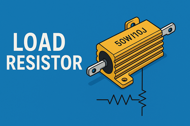 Load Resistor: Principles, Calculation and LED Applications
23 July 20253030
 Introduction to Lead Acid Battery: Construction, Working Principle and Types
04 March 20219543
 Classification and Selection of Industrial Connectors
11 February 20225329
 What are the Types of Camera Lenses?
18 June 20212247
 Toggle Switches: Features, Types and Applications
23 January 202110632
 Characteristics, Types, and Functions of Electrolytic Capacitors
17 October 20259646
 Intel Launches Industry's First Stackable, Shareable and Transferable One-Year Semiconductor Technician Certificate Program
26 September 20233001
Texas Instruments
In Stock: 2500
Minimum: 1 Multiples: 1
Qty
Unit Price
Ext Price
1
$0.720645
$0.72
10
$0.679854
$6.80
100
$0.641371
$64.14
500
$0.605067
$302.53
1000
$0.570818
$570.82
Not the price you want? Send RFQ Now and we'll contact you ASAP.
Inquire for More Quantity
![CD4029BE]() CD4029BE
CD4029BETexas Instruments
![SN74ALS163BNS]() SN74ALS163BNS
SN74ALS163BNSTexas Instruments
![SN74F280BNS]() SN74F280BNS
SN74F280BNSTexas Instruments
![SN74AS280NS]() SN74AS280NS
SN74AS280NSTexas Instruments
![SN74LS193NSR]() SN74LS193NSR
SN74LS193NSRTexas Instruments
![CD4060BM]() CD4060BM
CD4060BMTexas Instruments
![CD4017BM96]() CD4017BM96
CD4017BM96Texas Instruments
![SN74HC4040N]() SN74HC4040N
SN74HC4040NTexas Instruments
![SN74LS590N]() SN74LS590N
SN74LS590NTexas Instruments
![SN74HC4060DR]() SN74HC4060DR
SN74HC4060DRTexas Instruments


