
 Product
 Brand
Brand Articles
 Tools
Tools
EL817 Optocoupler: Package, Pinout, and Datasheet [Video&FAQ]

Renesas Electronics America Inc.
700pA Instrumentational OP Amps 0.004μA 2.4V~5.5V EL8170 8 Pins 8-SOIC (0.154, 3.90mm Width)
Unit Price: $2.740311
Ext Price: $2.74


700pA Instrumentational OP Amps 0.004μA 2.4V~5.5V EL8170 8 Pins 8-SOIC (0.154, 3.90mm Width)
The EL817 series of devices each consist of infrared emitting diodes, optically coupled to a phototransistor detector. This article mainly introduces package, pinout, datasheet and other detailed information about Renesas Electronics EL817.

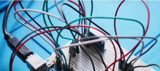
How to connect Micro Controller Peripherals to AC Power, using EL817 Optocoupler with 440/230V AC.
EL817 Description
The EL817 series of devices each consist of infrared emitting diodes, optically coupled to a phototransistor detector. They are packaged in a 4-pin DIP package and available in wide-lead spacing and SMD options.
The EL817 is a micropower instrumentation amplifier optimized for single-supply operation over the +2.4V to +5.5 V range, Inputs and outputs can operate rail-to-rail. The EL817 also delivers excellent DC and AC specifications while consuming only 65µA typical supply current. As with all instrumentation amplifiers, a pair of inputs provide very high common-mode rejection and are completely independent of a pair of feedback terminals.
The feedback terminals allow zero input to be translated to any output offset, including ground. A feedback divider controls the overall gain of the amplifier. The EL817 is compensated for a gain of 100 or more, also it has bipolar input devices for best offset and 1/f noise performance. The amplifiers can be operated from one lithium cell or two Ni-Cd batteries. The EL817 input range includes ground to slightly above positive rail. The output stage swings to the ground and positive supply (no pull-up or pull-down resistors are needed).
EL817 Pinout
The following figures are showing the Pinout and the related circuits to you.

Pinout
| Pin Number | Pin Name | Equivalent Circuit | Description |
| 1 | DNC | Do Not Connect; Internal connection - Must be left floating. | |
| 2 | IN- | Circuit 1A | High impedance input terminals. The EL817 input circuit is shown in Circuit 1A. The EL817: to avoid offset drift, it is recommended that the terminals are not overdriven beyond 1V and the input current must never exceed 5mA. |
| 3 | IN+ | Circuit 1A | |
| 4 | V- | Circuit 3 | Negative supply terminal. |
| 5 | FB- | Circuit 1A | High impedance feedback terminals. The EL817 input circuit is shown in Circuit 1A. |
| 6 | VOUT | Circuit 2 | Output voltage. |
| 7 | V+ | Circuit 3 | Positive supply terminal. |
| 8 | FB+ | Circuit 1A | The EL817: to avoid offset drift, it is recommended that the terminals are not overdriven beyond 1V and the input current must never exceed 5mA. |

Circuit 1A

Circuit 2

Circuit 3
EL817 CAD Model
The following figure is the Footprint and 3D Model of EL817.

Footprint

3D Model
EL817 Features
• 95µA Maximum Supply Current
• Maximum Offset Voltage
- 200µV (EL8170)
- 1000µV (EL8173)
• Maximum 3nA Input Bias Current
• 396kHz -3dB Bandwidth (G = 10)
• 192kHz -3dB Bandwidth (G = 100)
• Single Supply Operation
- Input Voltage Range is Rail-to-rail
- Output Swings Rail-to-rail
• Pb-Free (RoHS Compliant)
Specifications
- TypeParameter
- Factory Lead Time33 Weeks
- Mounting Type
The "Mounting Type" in electronic components refers to the method used to attach or connect a component to a circuit board or other substrate, such as through-hole, surface-mount, or panel mount.
Surface Mount - Package / Case
refers to the protective housing that encases an electronic component, providing mechanical support, electrical connections, and thermal management.
8-SOIC (0.154, 3.90mm Width) - Surface Mount
having leads that are designed to be soldered on the side of a circuit board that the body of the component is mounted on.
YES - Operating Temperature
The operating temperature is the range of ambient temperature within which a power supply, or any other electrical equipment, operate in. This ranges from a minimum operating temperature, to a peak or maximum operating temperature, outside which, the power supply may fail.
-40°C~125°C - Packaging
Semiconductor package is a carrier / shell used to contain and cover one or more semiconductor components or integrated circuits. The material of the shell can be metal, plastic, glass or ceramic.
Tube - JESD-609 Code
The "JESD-609 Code" in electronic components refers to a standardized marking code that indicates the lead-free solder composition and finish of electronic components for compliance with environmental regulations.
e3 - Part Status
Parts can have many statuses as they progress through the configuration, analysis, review, and approval stages.
Active - Moisture Sensitivity Level (MSL)
Moisture Sensitivity Level (MSL) is a standardized rating that indicates the susceptibility of electronic components, particularly semiconductors, to moisture-induced damage during storage and the soldering process, defining the allowable exposure time to ambient conditions before they require special handling or baking to prevent failures
3 (168 Hours) - Number of Terminations8
- ECCN Code
An ECCN (Export Control Classification Number) is an alphanumeric code used by the U.S. Bureau of Industry and Security to identify and categorize electronic components and other dual-use items that may require an export license based on their technical characteristics and potential for military use.
EAR99 - Terminal Finish
Terminal Finish refers to the surface treatment applied to the terminals or leads of electronic components to enhance their performance and longevity. It can improve solderability, corrosion resistance, and overall reliability of the connection in electronic assemblies. Common finishes include nickel, gold, and tin, each possessing distinct properties suitable for various applications. The choice of terminal finish can significantly impact the durability and effectiveness of electronic devices.
Matte Tin (Sn) - annealed - Terminal Position
In electronic components, the term "Terminal Position" refers to the physical location of the connection points on the component where external electrical connections can be made. These connection points, known as terminals, are typically used to attach wires, leads, or other components to the main body of the electronic component. The terminal position is important for ensuring proper connectivity and functionality of the component within a circuit. It is often specified in technical datasheets or component specifications to help designers and engineers understand how to properly integrate the component into their circuit designs.
DUAL - Terminal Form
Occurring at or forming the end of a series, succession, or the like; closing; concluding.
GULL WING - Peak Reflow Temperature (Cel)
Peak Reflow Temperature (Cel) is a parameter that specifies the maximum temperature at which an electronic component can be exposed during the reflow soldering process. Reflow soldering is a common method used to attach electronic components to a circuit board. The Peak Reflow Temperature is crucial because it ensures that the component is not damaged or degraded during the soldering process. Exceeding the specified Peak Reflow Temperature can lead to issues such as component failure, reduced performance, or even permanent damage to the component. It is important for manufacturers and assemblers to adhere to the recommended Peak Reflow Temperature to ensure the reliability and functionality of the electronic components.
NOT SPECIFIED - Number of Functions1
- Supply Voltage
Supply voltage refers to the electrical potential difference provided to an electronic component or circuit. It is crucial for the proper operation of devices, as it powers their functions and determines performance characteristics. The supply voltage must be within specified limits to ensure reliability and prevent damage to components. Different electronic devices have specific supply voltage requirements, which can vary widely depending on their design and intended application.
5V - Time@Peak Reflow Temperature-Max (s)
Time@Peak Reflow Temperature-Max (s) refers to the maximum duration that an electronic component can be exposed to the peak reflow temperature during the soldering process, which is crucial for ensuring reliable solder joint formation without damaging the component.
NOT SPECIFIED - Base Part Number
The "Base Part Number" (BPN) in electronic components serves a similar purpose to the "Base Product Number." It refers to the primary identifier for a component that captures the essential characteristics shared by a group of similar components. The BPN provides a fundamental way to reference a family or series of components without specifying all the variations and specific details.
EL8170 - Pin Count
a count of all of the component leads (or pins)
8 - JESD-30 Code
JESD-30 Code refers to a standardized descriptive designation system established by JEDEC for semiconductor-device packages. This system provides a systematic method for generating designators that convey essential information about the package's physical characteristics, such as size and shape, which aids in component identification and selection. By using JESD-30 codes, manufacturers and engineers can ensure consistency and clarity in the specification of semiconductor packages across various applications and industries.
R-PDSO-G8 - Output Type
The "Output Type" parameter in electronic components refers to the type of signal or data that is produced by the component as an output. This parameter specifies the nature of the output signal, such as analog or digital, and can also include details about the voltage levels, current levels, frequency, and other characteristics of the output signal. Understanding the output type of a component is crucial for ensuring compatibility with other components in a circuit or system, as well as for determining how the output signal can be utilized or processed further. In summary, the output type parameter provides essential information about the nature of the signal that is generated by the electronic component as its output.
Rail-to-Rail - Number of Circuits1
- Current - Supply
Current - Supply is a parameter in electronic components that refers to the maximum amount of electrical current that the component can provide to the circuit it is connected to. It is typically measured in units of amperes (A) and is crucial for determining the power handling capability of the component. Understanding the current supply rating is important for ensuring that the component can safely deliver the required current without overheating or failing. It is essential to consider this parameter when designing circuits to prevent damage to the component and ensure proper functionality of the overall system.
65μA - Slew Rate
the maximum rate of output voltage change per unit time.
0.55V/μs - Amplifier Type
Amplifier Type refers to the classification or categorization of amplifiers based on their design, functionality, and characteristics. Amplifiers are electronic devices that increase the amplitude of a signal, such as voltage or current. The type of amplifier determines its specific application, performance capabilities, and operating characteristics. Common types of amplifiers include operational amplifiers (op-amps), power amplifiers, audio amplifiers, and radio frequency (RF) amplifiers. Understanding the amplifier type is crucial for selecting the right component for a particular circuit or system design.
Instrumentation - Current - Input Bias
The parameter "Current - Input Bias" in electronic components refers to the amount of current required at the input terminal of a device to maintain proper operation. It is a crucial specification as it determines the minimum input current needed for the component to function correctly. Input bias current can affect the performance and accuracy of the device, especially in precision applications where small signal levels are involved. It is typically specified in datasheets for operational amplifiers, transistors, and other semiconductor devices to provide users with important information for circuit design and analysis.
700pA - Voltage - Supply, Single/Dual (±)
The parameter "Voltage - Supply, Single/Dual (±)" in electronic components refers to the power supply voltage required for the proper operation of the component. This parameter indicates whether the component requires a single power supply voltage (e.g., 5V) or a dual power supply voltage (e.g., ±15V). For components that require a single power supply voltage, only one voltage level is needed for operation. On the other hand, components that require a dual power supply voltage need both positive and negative voltage levels to function correctly.Understanding the voltage supply requirements of electronic components is crucial for designing and integrating them into circuits to ensure proper functionality and prevent damage due to incorrect voltage levels.
2.4V~5.5V - Bandwidth
In electronic components, "Bandwidth" refers to the range of frequencies over which the component can effectively operate or pass signals without significant loss or distortion. It is a crucial parameter for devices like amplifiers, filters, and communication systems. The bandwidth is typically defined as the difference between the upper and lower frequencies at which the component's performance meets specified criteria, such as a certain level of signal attenuation or distortion. A wider bandwidth indicates that the component can handle a broader range of frequencies, making it more versatile for various applications. Understanding the bandwidth of electronic components is essential for designing and optimizing circuits to ensure proper signal transmission and reception within the desired frequency range.
192 kHz - Average Bias Current-Max (IIB)
The parameter "Average Bias Current-Max (IIB)" in electronic components refers to the maximum average bias current that the component can handle without exceeding its specified operating limits. Bias current is the current that flows through a component when it is in its quiescent state or when it is not actively processing a signal. Exceeding the maximum average bias current can lead to overheating, reduced performance, or even damage to the component. Therefore, it is important to ensure that the bias current does not exceed the specified maximum value to maintain the reliability and longevity of the electronic component.
0.004μA - Supply Voltage Limit-Max
The parameter "Supply Voltage Limit-Max" in electronic components refers to the maximum voltage that the component can safely handle without getting damaged. This specification is crucial for ensuring the reliable operation and longevity of the component within a given electrical system. Exceeding the maximum supply voltage limit can lead to overheating, electrical breakdown, or permanent damage to the component. It is important to carefully adhere to this limit when designing and operating electronic circuits to prevent potential failures and ensure the overall system's performance and safety.
5.75V - Voltage - Input Offset
Voltage - Input Offset is a parameter that refers to the difference in voltage between the input terminals of an electronic component, such as an operational amplifier, when the input voltage is zero. It is an important characteristic that can affect the accuracy and performance of the component in various applications. A low input offset voltage is desirable as it indicates that the component will have minimal error in its output when the input signal is near zero. Manufacturers typically provide this specification in the component's datasheet to help users understand the component's behavior and make informed decisions when designing circuits.
50μV - Input Offset Current-Max (IIO)
Input Offset Current-Max (IIO) is a parameter that describes the maximum difference in input bias currents between two input terminals of an electronic component, such as an operational amplifier. Input offset current can cause errors in the output of the component, especially in precision applications where accuracy is crucial. The IIO specification provides a limit on the maximum allowable difference in input currents to ensure that the component operates within its specified performance range. Designers need to consider the IIO value when selecting components and designing circuits to minimize errors and ensure reliable operation.
0.003μA - Common-mode Reject Ratio-Min
The Common-mode Reject Ratio (CMRR) is a parameter used to measure the ability of an electronic component, such as an operational amplifier, to reject common-mode signals. Common-mode signals are signals that appear on both input terminals of the component simultaneously. The CMRR is defined as the ratio of the differential gain to the common-mode gain of the component. A higher CMRR value indicates better rejection of common-mode signals, meaning that the component is more effective at amplifying only the desired differential signal while ignoring unwanted common-mode noise. The "Common-mode Reject Ratio-Min" parameter specifies the minimum acceptable value of CMRR for the component to function properly within its specified operating conditions.
85 dB - Length4.9mm
- RoHS Status
RoHS means “Restriction of Certain Hazardous Substances” in the “Hazardous Substances Directive” in electrical and electronic equipment.
ROHS3 Compliant
EL817 Voltage Measuring Circuit

EL817 Applications
• Battery- or Solar-Powered Systems
• Strain Gauges
• Current Monitors
• Thermocouple Amplifiers
EL817 Package


EL817 Manufacturer
Renesas Electronics, as a well-known microcontroller supplier and leader in analog and power SoC products, focuses on the development of competitive semiconductor solutions through embedded design innovation. These solutions are designed to optimize the billions of devices used to improve people's work and lifestyle.
Renesas is committed to providing a wealth of expertise and high-quality solutions for a variety of applications to shape an unlimited future, including automotive, industrial, home electronics (HE), office automation (OA), and information and communication technology (ICT).
Trend Analysis
Datasheet PDF
- Datasheets :
- PCN Assembly/Origin :
- ConflictMineralStatement :
1.How to connect EL817 optical lotus to 12V power supply?
If you just switch between high and low levels, it’s true as mentioned above, you can put the input signal on the anode of the diode and pin 1 of the optocoupler, or put the output signal on the E pole of the transistor and pin 4 of the photocoupler. This can be used. The phase is opposite, but generally speaking, we use a common-emitter circuit, so it is still recommended to change the input signal position. As for the resistance, it is generally 100O~1kO for signal detection.
2.What is the difference between EL817 optocoupler and MOC3063 optocoupler? Is it interchangeable?
EL817 uses LED + photosensitive transistor for coupling, and the output has the characteristics of a transistor. Can only control DC MOC3063 adopts LED + Triac for coupling, and the output has the characteristics of triac. Can only control communication. Therefore it cannot be replaced.
3.What is the difference between EL817 and PC817?
The same, they are all optocouplers. PC817 is more common, and EL817 is produced by Taiwan Everlight. PC and EL are the shortcodes of their R&D company. For example, there is a power amplifier chip called LM4871, and another kind of XPT4871 developed in Shenzhen. The two are completely universal.
 AT89C5115 Microcontroller: Comprehensive Overview and Applications
29 February 2024145
 TL431AIDBZR IC: Features, Applications and Datasheet
31 October 2023547
 LM5175QPWPTQ1 DC/DC Controller: Pinout, Specification, and Datasheet
01 July 20211885
 MIC5219 LDO Regulator: Datasheet, Pinout and Circuit
04 August 20214854
 STM32F401RET6 vs GD32 Microcontrollers Key Differences
24 July 20251578
 STM32MP157CAA3 Development: From Setup and Configuration to Advanced Features Implementation
07 June 20251230
 BU407 Transistor: Datasheet, Pinout, Equivalent
03 December 20213788
 BAT54J Diode: SOD323F, 30V, Datasheet, Pinout, Application
18 February 20221471
 Comparing Popular Jumper Wires for Electronics Projects
10 July 20252226
 An overview of Flip-flop
10 December 20204332
 Basic Introduction to System on a Chip
02 December 20204409
 Wireless Charging Explained: Working and Standards
26 May 202110478
 50 World Famous Sensor Manufacturing Companies
31 October 2025895338
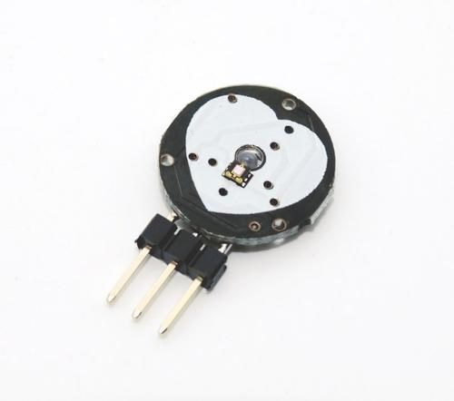 Pulse Sensor-Definition, Working and Applications
28 January 20214728
 Semiconductor Material Industry Guide
21 January 20226572
 What is 3D XPoint?
09 November 20214708
Renesas Electronics America Inc.
In Stock: 1659
Minimum: 1 Multiples: 1
Qty
Unit Price
Ext Price
1
$2.740311
$2.74
10
$2.585199
$25.85
100
$2.438867
$243.89
500
$2.300818
$1,150.41
1000
$2.170583
$2,170.58
Not the price you want? Send RFQ Now and we'll contact you ASAP.
Inquire for More Quantity
![HA1630Q06TELL-E]() HA1630Q06TELL-E
HA1630Q06TELL-ERenesas Electronics America
![HA1630D06TEL-E]() HA1630D06TEL-E
HA1630D06TEL-ERenesas Electronics America
![UPC3218GV-E1-A]() UPC3218GV-E1-A
UPC3218GV-E1-ARenesas
![UPC3221GV-E1-A]() UPC3221GV-E1-A
UPC3221GV-E1-ARenesas
![UPC842G2-E2-A]() UPC842G2-E2-A
UPC842G2-E2-ARenesas
![PS8551L4-E3-AX]() PS8551L4-E3-AX
PS8551L4-E3-AXRenesas Electronics America
![ISL28236FUZ-T7]() ISL28236FUZ-T7
ISL28236FUZ-T7Renesas Electronics America Inc.
![UPC834G2-E2-A]() UPC834G2-E2-A
UPC834G2-E2-ARenesas
![ISL28158FHZ-T7A]() ISL28158FHZ-T7A
ISL28158FHZ-T7ARenesas Electronics America Inc.
![HA1630D06MMEL-E]() HA1630D06MMEL-E
HA1630D06MMEL-ERenesas Electronics America


