
 Product
 Brand
Brand Articles
 Tools
Tools
LM4041 Bandgap Circuit: Pinout, Features and Datasheet

-40°C~125°C TA Fixed 0.95mm PMIC LM4041 TO-236-3, SC-59, SOT-23-3
Unit Price: $0.172010
Ext Price: $0.17


-40°C~125°C TA Fixed 0.95mm PMIC LM4041 TO-236-3, SC-59, SOT-23-3
The LM4041 is a bandgap circuit designed to achieve a precision micro-power voltage reference of 1.225 V. Furthermore, Huge range of Semiconductors, Capacitors, Resistors and IcS in stock. Welcome RFQ.
LM4041 Pinout

pinout
LM4041 CAD Model

symbol

footprint
LM4041 Overview
The LM4041 is a bandgap circuit designed to achieve a precision micro-power voltage reference of 1.225 V. The device is available in the small outline SOT23 and SC70-5 surface mount packages which are ideal for applications where space saving is important. Both packages are available to 0.5% C grade and 1% D grade for precision applications. Excellent performance is maintained over the 60µA to 12mA operating current range with a typical temperature coefficient of only 20ppm/°C. The device has been designed to be highly tolerant of capacitive loads so maintaining excellent stability. This device offers a pin for pin compatible alternative to the LM4041 voltage reference in both adjustable and 1.225V output variants.
This article provides you with a basic overview of the LM4041, including its pin descriptions, features and specifications, etc., to help you quickly understand what LM4041 is.
LM4041 Features
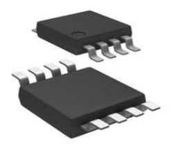
• Small packages: SOT23, SC70-5
• No output capacitor required
• Output voltage tolerance
• LM4041C: ±0.5% at 25°C
• LM4041D: ±1% at 25°C
• Low output noise: 20µVrms (10Hz to 10kHz)
• Wide operating current range: 60µA to 12mA
• Extended temperature range: -40°C to +125°C
• Low temperature coefficient : 100ppm/°C (max)
• All parts AEC-Q100 Grade1 qualified
Specifications
- TypeParameter
- Factory Lead Time19 Weeks
- Mount
In electronic components, the term "Mount" typically refers to the method or process of physically attaching or fixing a component onto a circuit board or other electronic device. This can involve soldering, adhesive bonding, or other techniques to secure the component in place. The mounting process is crucial for ensuring proper electrical connections and mechanical stability within the electronic system. Different components may have specific mounting requirements based on their size, shape, and function, and manufacturers provide guidelines for proper mounting procedures to ensure optimal performance and reliability of the electronic device.
Surface Mount - Mounting Type
The "Mounting Type" in electronic components refers to the method used to attach or connect a component to a circuit board or other substrate, such as through-hole, surface-mount, or panel mount.
Surface Mount - Package / Case
refers to the protective housing that encases an electronic component, providing mechanical support, electrical connections, and thermal management.
TO-236-3, SC-59, SOT-23-3 - Number of Pins3
- Weight7.994566mg
- Usage LevelCommercial grade
- Operating Temperature
The operating temperature is the range of ambient temperature within which a power supply, or any other electrical equipment, operate in. This ranges from a minimum operating temperature, to a peak or maximum operating temperature, outside which, the power supply may fail.
-40°C~125°C TA - Packaging
Semiconductor package is a carrier / shell used to contain and cover one or more semiconductor components or integrated circuits. The material of the shell can be metal, plastic, glass or ceramic.
Tape & Reel (TR) - Published2010
- Tolerance
In electronic components, "tolerance" refers to the acceptable deviation or variation from the specified or ideal value of a particular parameter, such as resistance, capacitance, or voltage. It indicates the range within which the actual value of the component can fluctuate while still being considered acceptable for use in a circuit. Tolerance is typically expressed as a percentage or a specific value and is important for ensuring the accuracy and reliability of electronic devices. Components with tighter tolerances are more precise but may also be more expensive. It is crucial to consider tolerance when selecting components to ensure proper functionality and performance of the circuit.
±1% - JESD-609 Code
The "JESD-609 Code" in electronic components refers to a standardized marking code that indicates the lead-free solder composition and finish of electronic components for compliance with environmental regulations.
e3 - Pbfree Code
The "Pbfree Code" parameter in electronic components refers to the code or marking used to indicate that the component is lead-free. Lead (Pb) is a toxic substance that has been widely used in electronic components for many years, but due to environmental concerns, there has been a shift towards lead-free alternatives. The Pbfree Code helps manufacturers and users easily identify components that do not contain lead, ensuring compliance with regulations and promoting environmentally friendly practices. It is important to pay attention to the Pbfree Code when selecting electronic components to ensure they meet the necessary requirements for lead-free applications.
yes - Part Status
Parts can have many statuses as they progress through the configuration, analysis, review, and approval stages.
Active - Moisture Sensitivity Level (MSL)
Moisture Sensitivity Level (MSL) is a standardized rating that indicates the susceptibility of electronic components, particularly semiconductors, to moisture-induced damage during storage and the soldering process, defining the allowable exposure time to ambient conditions before they require special handling or baking to prevent failures
1 (Unlimited) - Number of Terminations3
- ECCN Code
An ECCN (Export Control Classification Number) is an alphanumeric code used by the U.S. Bureau of Industry and Security to identify and categorize electronic components and other dual-use items that may require an export license based on their technical characteristics and potential for military use.
EAR99 - Temperature Coefficient
The resistance-change factor per degree Celsius of temperature change is called the temperature coefficient of resistance. This factor is represented by the Greek lower-case letter “alpha” (α). A positive coefficient for a material means that its resistance increases with an increase in temperature.
150ppm/°C - Terminal Finish
Terminal Finish refers to the surface treatment applied to the terminals or leads of electronic components to enhance their performance and longevity. It can improve solderability, corrosion resistance, and overall reliability of the connection in electronic assemblies. Common finishes include nickel, gold, and tin, each possessing distinct properties suitable for various applications. The choice of terminal finish can significantly impact the durability and effectiveness of electronic devices.
Matte Tin (Sn) - Terminal Position
In electronic components, the term "Terminal Position" refers to the physical location of the connection points on the component where external electrical connections can be made. These connection points, known as terminals, are typically used to attach wires, leads, or other components to the main body of the electronic component. The terminal position is important for ensuring proper connectivity and functionality of the component within a circuit. It is often specified in technical datasheets or component specifications to help designers and engineers understand how to properly integrate the component into their circuit designs.
DUAL - Terminal Form
Occurring at or forming the end of a series, succession, or the like; closing; concluding.
GULL WING - Peak Reflow Temperature (Cel)
Peak Reflow Temperature (Cel) is a parameter that specifies the maximum temperature at which an electronic component can be exposed during the reflow soldering process. Reflow soldering is a common method used to attach electronic components to a circuit board. The Peak Reflow Temperature is crucial because it ensures that the component is not damaged or degraded during the soldering process. Exceeding the specified Peak Reflow Temperature can lead to issues such as component failure, reduced performance, or even permanent damage to the component. It is important for manufacturers and assemblers to adhere to the recommended Peak Reflow Temperature to ensure the reliability and functionality of the electronic components.
260 - Number of Functions1
- Terminal Pitch
The center distance from one pole to the next.
0.95mm - Current Rating
Current rating is the maximum current that a fuse will carry for an indefinite period without too much deterioration of the fuse element.
12mA - Time@Peak Reflow Temperature-Max (s)
Time@Peak Reflow Temperature-Max (s) refers to the maximum duration that an electronic component can be exposed to the peak reflow temperature during the soldering process, which is crucial for ensuring reliable solder joint formation without damaging the component.
40 - Base Part Number
The "Base Part Number" (BPN) in electronic components serves a similar purpose to the "Base Product Number." It refers to the primary identifier for a component that captures the essential characteristics shared by a group of similar components. The BPN provides a fundamental way to reference a family or series of components without specifying all the variations and specific details.
LM4041 - Pin Count
a count of all of the component leads (or pins)
3 - Number of Outputs1
- Output Voltage
Output voltage is a crucial parameter in electronic components that refers to the voltage level produced by the component as a result of its operation. It represents the electrical potential difference between the output terminal of the component and a reference point, typically ground. The output voltage is a key factor in determining the performance and functionality of the component, as it dictates the level of voltage that will be delivered to the connected circuit or load. It is often specified in datasheets and technical specifications to ensure compatibility and proper functioning within a given system.
1.225V - Output Type
The "Output Type" parameter in electronic components refers to the type of signal or data that is produced by the component as an output. This parameter specifies the nature of the output signal, such as analog or digital, and can also include details about the voltage levels, current levels, frequency, and other characteristics of the output signal. Understanding the output type of a component is crucial for ensuring compatibility with other components in a circuit or system, as well as for determining how the output signal can be utilized or processed further. In summary, the output type parameter provides essential information about the nature of the signal that is generated by the electronic component as its output.
Fixed - Max Output Current
The maximum current that can be supplied to the load.
12mA - Trim/Adjustable Output
Trim or adjustable output refers to the ability of an electronic component, such as a voltage regulator or power supply, to produce an output voltage that can be finely tuned or adjusted to meet specific requirements. This feature allows for precise control over the output voltage level, accommodating variations in load conditions or desired operational parameters. Users can typically achieve this adjustment through external resistors, potentiometers, or internal calibration mechanisms, ensuring optimal performance in diverse applications.
NO - Analog IC - Other Type
Analog IC - Other Type is a parameter used to categorize electronic components that are integrated circuits (ICs) designed for analog signal processing but do not fall into more specific subcategories such as amplifiers, comparators, or voltage regulators. These ICs may include specialized analog functions such as analog-to-digital converters (ADCs), digital-to-analog converters (DACs), voltage references, or signal conditioning circuits. They are typically used in various applications where precise analog signal processing is required, such as in audio equipment, instrumentation, communication systems, and industrial control systems. Manufacturers provide detailed specifications for these components to help engineers select the most suitable IC for their specific design requirements.
TWO TERMINAL VOLTAGE REFERENCE - Max Output Voltage
The maximum output voltage refers to the dynamic area beyond which the output is saturated in the positive or negative direction, and is limited according to the load resistance value.
1.225V - Reference Voltage
A voltage reference is an electronic device that ideally produces a fixed (constant) voltage irrespective of the loading on the device, power supply variations, temperature changes, and the passage of time. Voltage references are used in power supplies, analog-to-digital converters, digital-to-analog converters, and other measurement and control systems. Voltage references vary widely in performance; a regulator for a computer power supply may only hold its value to within a few percent of the nominal value, whereas laboratory voltage standards have precisions and stability measured in parts per million.
1.225V - Reference Type
a code object that is not stored directly where it is created, but that acts as a kind of pointer to a value stored elsewhere.
Shunt - Min Output Voltage
Min Output Voltage refers to the lowest voltage level that an electronic component, such as a voltage regulator or power supply, can provide reliably under specified conditions. It indicates the minimum threshold required for proper operation of connected devices. Operating below this voltage may lead to device malfunction or failure to operate as intended.
1.225V - Temp Coef of Voltage-Max
The parameter "Temp Coef of Voltage-Max" refers to the temperature coefficient of the maximum voltage rating of an electronic component. It indicates how the maximum voltage that the component can handle varies with temperature changes. A positive temperature coefficient means that the maximum voltage increases with temperature, while a negative coefficient indicates a decrease. This parameter is crucial for ensuring reliable performance and preventing breakdowns under different operating temperatures.
150 ppm/°C - Current - Cathode
Current - Cathode refers to the flow of electric current through the cathode terminal of an electronic component, such as a diode or a vacuum tube. It represents the amount of charge carriers, typically electrons, moving towards the cathode during operation. This parameter is crucial for determining the component's functionality and performance characteristics, as it influences the efficiency and stability of the circuit. High cathode current can indicate increased power consumption or potential overheating issues if not managed properly.
73μA - Noise - 10Hz to 10kHz
The parameter "Noise - 10Hz to 10kHz" in electronic components refers to the level of unwanted electrical signals or interference present within the specified frequency range of 10Hz to 10kHz. This noise can be generated by various sources such as electromagnetic interference, thermal noise, or crosstalk. It is important to minimize this noise in electronic components as it can degrade the performance of the device or system by affecting signal quality or introducing errors. Manufacturers often provide specifications for noise levels to help designers select components that meet their requirements for noise performance.
20μVrms - Height1.02mm
- Length3.04mm
- Width1.4mm
- REACH SVHC
The parameter "REACH SVHC" in electronic components refers to the compliance with the Registration, Evaluation, Authorization, and Restriction of Chemicals (REACH) regulation regarding Substances of Very High Concern (SVHC). SVHCs are substances that may have serious effects on human health or the environment, and their use is regulated under REACH to ensure their safe handling and minimize their impact.Manufacturers of electronic components need to declare if their products contain any SVHCs above a certain threshold concentration and provide information on the safe use of these substances. This information allows customers to make informed decisions about the potential risks associated with using the components and take appropriate measures to mitigate any hazards.Ensuring compliance with REACH SVHC requirements is essential for electronics manufacturers to meet regulatory standards, protect human health and the environment, and maintain transparency in their supply chain. It also demonstrates a commitment to sustainability and responsible manufacturing practices in the electronics industry.
No SVHC - Radiation Hardening
Radiation hardening is the process of making electronic components and circuits resistant to damage or malfunction caused by high levels of ionizing radiation, especially for environments in outer space (especially beyond the low Earth orbit), around nuclear reactors and particle accelerators, or during nuclear accidents or nuclear warfare.
No - RoHS Status
RoHS means “Restriction of Certain Hazardous Substances” in the “Hazardous Substances Directive” in electrical and electronic equipment.
ROHS3 Compliant - Lead Free
Lead Free is a term used to describe electronic components that do not contain lead as part of their composition. Lead is a toxic material that can have harmful effects on human health and the environment, so the electronics industry has been moving towards lead-free components to reduce these risks. Lead-free components are typically made using alternative materials such as silver, copper, and tin. Manufacturers must comply with regulations such as the Restriction of Hazardous Substances (RoHS) directive to ensure that their products are lead-free and environmentally friendly.
Lead Free
LM4041 Functional Block Diagram

functional block diagram
LM4041 Equivalent
| Model number | Manufacturer | Description |
| LM4041DFTA | Diodes Incorporated | Two Terminal Voltage Reference, 1 Output, 1.225V, CMOS, PDSO3, SOT-23, 3 PIN. |
| LM4041CFTA | Diodes Incorporated | Two Terminal Voltage Reference, 1 Output, 1.225V, CMOS, PDSO3, SOT-23, 3 PIN |
Parts with Similar Specs
- ImagePart NumberManufacturerPackage / CaseNumber of PinsMax Output CurrentMin Output VoltageOutput VoltageMax Output VoltageToleranceTemperature CoefficientView Compare
![LM4041DFTA]()
LM4041DFTA
TO-236-3, SC-59, SOT-23-3
3
12 mA
1.225 V
1.225 V
1.225 V
±1%
150ppm/°C
![LM4041D12IDBZR]()
TO-236-3, SC-59, SOT-23-3
3
12 mA
1.225 V
1.225 V
1.225 V
±1%
150ppm/°C
![LM4041DIM3-1.2]()
TO-236-3, SC-59, SOT-23-3
3
12 mA
1.225 V
1.225 V
1.225 V
±0.5%
120ppm/°C
![LM4041DEM3-1.2]()
TO-236-3, SC-59, SOT-23-3
3
12 mA
1.225 V
1.225 V
1.225 V
±1%
150ppm/°C
![TS4041CILT-1.2]()
TO-236-3, SC-59, SOT-23-3
3
12 mA
1.225 V
1.225 V
1.225 V
±1%
150ppm/°C


LM4041 Application
• Battery powered equipment
• Precision power supplies
• Portable instrumentation
• Portable communications devices
• Notebook and palmtop computers
• Data acquisition systems
LM4041 Package

package
LM4041 Manufacturer
Diodes Incorporated is devoted to be the leading provider for large-volume and high-growing markets. With cutting-edge products of package technology, analog, discrete and mixed-signal products, Diodes Incorporated is capable to provide high-quality semiconductor products to meet the customers’ needs from walks of communications, computing, consumer electronics, automotive and industrial markets. Their product lines cover a wide range of application solutions together with 25 operations around the world which serve with examine, engineering, manufacturing and customer service.
Datasheet PDF
- Environmental Information :
- RohsStatement :
- Datasheets :
- PCN Assembly/Origin :
Trend Analysis
How about the stability of LM4041?
The device has been designed to be highly tolerant of capacitive loads, so maintaining excellent stability.
Does the LM4041 save space?
The device is available in the small outline SOT23 and SC70-5 surface mount packages which are ideal for applications where space saving is important.
What is the essential property of the LM4041?
The LM4041 is a bandgap circuit designed to achieve a precision micro-power voltage reference of 1.225 V.
 RC4558 Operational Amplifier: Datasheet, Replacement and Pinout
20 August 20213817
 MCP1253 DC/DC Converter: Specifications, Pinout and Datasheet
12 October 2021963
 SST39SF020A 2 Mbit Multi-Purpose Flash: Pinout, Equivalent and Datasheet
31 March 20221289
 2N2907 Bipolar PNP Transistor: Pinout, Datasheet and Equivalent
20 May 20219316
 PIC18F4620 Enhanced Flash Microcontrollers:Pinout, Features, and Datasheet
13 September 20212634
 Realtek RTD1296: 4K Smart TV Box Solution
29 February 2024624
![LTC4054 Single-cell Lithium-ion Battery: Circuits, Pinout, and Datasheet [Video]](https://res.utmel.com/Images/Article/a849e0f4-9fdc-4e4e-9f76-e520361f732a.png) LTC4054 Single-cell Lithium-ion Battery: Circuits, Pinout, and Datasheet [Video]
LTC4054 Single-cell Lithium-ion Battery: Circuits, Pinout, and Datasheet [Video]04 January 202214637
 AVR® ATtiny 2KB Flash MCU: Hardware UART & 20MHz Performance Analysis
05 February 202664
 What is an Accelerometer Sensor?
20 April 202111881
 Chiplet Brings Change to the Business Model of IP Design Companies
05 September 20224155
 Function and Application of Laser Sensors
28 October 20257428
 How Many Types of Inverters are There?
28 March 202217435
 Tough Times for Japanese Component Manufacturers
10 August 20222838
 What is Color Ring Inductor? How to Read Inductor Color Code?
01 April 202514627
 Modeling, Modulation Analysis of Filter-Integrated Three-Switch Boost Inverter
12 April 20234352
 Humidity Sensor: Classification, Package and Application
13 November 20254270
Diodes Incorporated
In Stock: 3211
Minimum: 1 Multiples: 1
Qty
Unit Price
Ext Price
1
$0.172010
$0.17
10
$0.162273
$1.62
100
$0.153088
$15.31
500
$0.144423
$72.21
1000
$0.136248
$136.25
Not the price you want? Send RFQ Now and we'll contact you ASAP.
Inquire for More Quantity
![ZR431F01TA]() ZR431F01TA
ZR431F01TADiodes Incorporated
![TLV431BFTA]() TLV431BFTA
TLV431BFTADiodes Incorporated
![TLV431AFTA]() TLV431AFTA
TLV431AFTADiodes Incorporated
![LM4040D25FTA]() LM4040D25FTA
LM4040D25FTADiodes Incorporated
![ZR431F005TA]() ZR431F005TA
ZR431F005TADiodes Incorporated
![ZRC250F01TA]() ZRC250F01TA
ZRC250F01TADiodes Incorporated
![AZ431LBNTR-G1]() AZ431LBNTR-G1
AZ431LBNTR-G1Diodes Incorporated
![ZTL431AFFTA]() ZTL431AFFTA
ZTL431AFFTADiodes Incorporated
![ZRB500F01TA]() ZRB500F01TA
ZRB500F01TADiodes Incorporated
