
 Product
 Brand
Brand Articles
 Tools
Tools
LP5912-3.3DRVT LDO Regulator Pos, 1.8V 0.5A 6-Pin WSON EP T/R and 500mA Low-Noise


Enable, Power Good, Soft Start Fixed LP5912 PMIC 6-WDFN Exposed Pad
The LP5912-3.3DRVT is a 500mA ultra-low noise LDO6 pin WSON package. This article is going to introduce guidance details about LP5912-3.3DRVT LDO regulators. Furthermore, there is a huge range of LP5912-3.3DRVT in stock. Welcome your RFQ!

Linear and LDO regulators and Switch Mode Power Supply Tutorial
- What is LP5912-3.3DRVT?
- LP5912-3.3DRVT Pinout
- LP5912-3.3DRVT CAD Model
- Specifications
- LP5912-3.3DRVT Functional Block Diagram
- LP5912-3.3DRVT Features
- LP5912-3.3DRVT Applications
- LP5912-3.3DRVT Application Circuit
- LP5912-3.3DRVT Alternatives Comparison
- Parts with Similar Specs
- LP5912-3.3DRVT Package Outline
- LP5912-3.3DRVT Manufacturer
- Trend Analysis
- Datasheet PDF
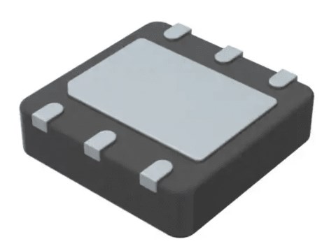
What is LP5912-3.3DRVT?
The LP5912-3.3DRVT is a WSON package with a 500mA extremely low noise LDO 6 pin. Low noise, high PSRR, low quiescent current, and low line and load transient response are all features of this LDO which are designed to fulfill the needs of RF and analog circuits. It has class-leading noise performance and the ability to place output capacitance remotely without the use of a noise bypass capacitor. This gadget is made to function with a ceramic capacitor with a 1F input and a 1F output (no separate noise bypass capacitor required). It's found in camera modules, sensors, Hi-Fi audio radio transceivers, PLL/synthesizers, clocks, and noise-sensitive medium-current applications.
LP5912-3.3DRVT Pinout

LP5912-3.3DRVT Pinout
LP5912-3.3DRVT CAD Model

LP5912-3.3DRVT Symbol

LP5912-3.3DRVT Footprint

LP5912-3.3DRVT 3D Model
Specifications
- TypeParameter
- Lifecycle Status
Lifecycle Status refers to the current stage of an electronic component in its product life cycle, indicating whether it is active, obsolete, or transitioning between these states. An active status means the component is in production and available for purchase. An obsolete status indicates that the component is no longer being manufactured or supported, and manufacturers typically provide a limited time frame for support. Understanding the lifecycle status is crucial for design engineers to ensure continuity and reliability in their projects.
ACTIVE (Last Updated: 1 day ago) - Factory Lead Time6 Weeks
- Mount
In electronic components, the term "Mount" typically refers to the method or process of physically attaching or fixing a component onto a circuit board or other electronic device. This can involve soldering, adhesive bonding, or other techniques to secure the component in place. The mounting process is crucial for ensuring proper electrical connections and mechanical stability within the electronic system. Different components may have specific mounting requirements based on their size, shape, and function, and manufacturers provide guidelines for proper mounting procedures to ensure optimal performance and reliability of the electronic device.
Surface Mount - Mounting Type
The "Mounting Type" in electronic components refers to the method used to attach or connect a component to a circuit board or other substrate, such as through-hole, surface-mount, or panel mount.
Surface Mount - Package / Case
refers to the protective housing that encases an electronic component, providing mechanical support, electrical connections, and thermal management.
6-WDFN Exposed Pad - Number of Pins6
- Operating Temperature
The operating temperature is the range of ambient temperature within which a power supply, or any other electrical equipment, operate in. This ranges from a minimum operating temperature, to a peak or maximum operating temperature, outside which, the power supply may fail.
-40°C~125°C TJ - Packaging
Semiconductor package is a carrier / shell used to contain and cover one or more semiconductor components or integrated circuits. The material of the shell can be metal, plastic, glass or ceramic.
Tape & Reel (TR) - JESD-609 Code
The "JESD-609 Code" in electronic components refers to a standardized marking code that indicates the lead-free solder composition and finish of electronic components for compliance with environmental regulations.
e4 - Pbfree Code
The "Pbfree Code" parameter in electronic components refers to the code or marking used to indicate that the component is lead-free. Lead (Pb) is a toxic substance that has been widely used in electronic components for many years, but due to environmental concerns, there has been a shift towards lead-free alternatives. The Pbfree Code helps manufacturers and users easily identify components that do not contain lead, ensuring compliance with regulations and promoting environmentally friendly practices. It is important to pay attention to the Pbfree Code when selecting electronic components to ensure they meet the necessary requirements for lead-free applications.
yes - Part Status
Parts can have many statuses as they progress through the configuration, analysis, review, and approval stages.
Active - Moisture Sensitivity Level (MSL)
Moisture Sensitivity Level (MSL) is a standardized rating that indicates the susceptibility of electronic components, particularly semiconductors, to moisture-induced damage during storage and the soldering process, defining the allowable exposure time to ambient conditions before they require special handling or baking to prevent failures
1 (Unlimited) - Number of Terminations6
- Terminal Finish
Terminal Finish refers to the surface treatment applied to the terminals or leads of electronic components to enhance their performance and longevity. It can improve solderability, corrosion resistance, and overall reliability of the connection in electronic assemblies. Common finishes include nickel, gold, and tin, each possessing distinct properties suitable for various applications. The choice of terminal finish can significantly impact the durability and effectiveness of electronic devices.
Nickel/Palladium/Gold (Ni/Pd/Au) - Terminal Position
In electronic components, the term "Terminal Position" refers to the physical location of the connection points on the component where external electrical connections can be made. These connection points, known as terminals, are typically used to attach wires, leads, or other components to the main body of the electronic component. The terminal position is important for ensuring proper connectivity and functionality of the component within a circuit. It is often specified in technical datasheets or component specifications to help designers and engineers understand how to properly integrate the component into their circuit designs.
DUAL - Terminal Form
Occurring at or forming the end of a series, succession, or the like; closing; concluding.
NO LEAD - Number of Functions1
- Base Part Number
The "Base Part Number" (BPN) in electronic components serves a similar purpose to the "Base Product Number." It refers to the primary identifier for a component that captures the essential characteristics shared by a group of similar components. The BPN provides a fundamental way to reference a family or series of components without specifying all the variations and specific details.
LP5912 - Current - Supply (Max)
The parameter "Current - Supply (Max)" in electronic components refers to the maximum amount of current that a component can draw from a power supply for its operation. This parameter is critical for ensuring that the power supply can adequately meet the demands of the component without causing damage or malfunction. Exceeding this specified maximum current can lead to overheating, reduced performance, or failure of the component. It is essential to consider this value when designing or integrating components into electronic circuits to maintain reliability and functionality.
600μA - Number of Outputs1
- Voltage - Input (Max)
Voltage - Input (Max) is a parameter in electronic components that specifies the maximum voltage that can be safely applied to the input of the component without causing damage. This parameter is crucial for ensuring the proper functioning and longevity of the component. Exceeding the maximum input voltage can lead to electrical overstress, which may result in permanent damage or failure of the component. It is important to carefully adhere to the specified maximum input voltage to prevent any potential issues and maintain the reliability of the electronic system.
6.5V - Output Voltage
Output voltage is a crucial parameter in electronic components that refers to the voltage level produced by the component as a result of its operation. It represents the electrical potential difference between the output terminal of the component and a reference point, typically ground. The output voltage is a key factor in determining the performance and functionality of the component, as it dictates the level of voltage that will be delivered to the connected circuit or load. It is often specified in datasheets and technical specifications to ensure compatibility and proper functioning within a given system.
3.3V - Output Type
The "Output Type" parameter in electronic components refers to the type of signal or data that is produced by the component as an output. This parameter specifies the nature of the output signal, such as analog or digital, and can also include details about the voltage levels, current levels, frequency, and other characteristics of the output signal. Understanding the output type of a component is crucial for ensuring compatibility with other components in a circuit or system, as well as for determining how the output signal can be utilized or processed further. In summary, the output type parameter provides essential information about the nature of the signal that is generated by the electronic component as its output.
Fixed - Output Configuration
Output Configuration in electronic components refers to the arrangement or setup of the output pins or terminals of a device. It defines how the output signals are structured and how they interact with external circuits or devices. The output configuration can determine the functionality and compatibility of the component in a circuit design. Common types of output configurations include single-ended, differential, open-drain, and push-pull configurations, each serving different purposes and applications in electronic systems. Understanding the output configuration of a component is crucial for proper integration and operation within a circuit.
Positive - Quiescent Current
The quiescent current is defined as the current level in the amplifier when it is producing an output of zero.
30μA - Control Features
Control features in electronic components refer to specific functionalities or characteristics that allow users to manage and regulate the operation of the component. These features are designed to provide users with control over various aspects of the component's performance, such as adjusting settings, monitoring parameters, or enabling specific modes of operation. Control features can include options for input/output configurations, power management, communication protocols, and other settings that help users customize and optimize the component's behavior according to their requirements. Overall, control features play a crucial role in enhancing the flexibility, usability, and performance of electronic components in various applications.
Enable, Power Good, Soft Start - Output Voltage 1
Output Voltage 1 is a parameter commonly found in electronic components such as voltage regulators, power supplies, and amplifiers. It refers to the voltage level that is produced or delivered by the component at a specific output terminal or pin. This parameter is crucial for determining the performance and functionality of the component in a circuit. The specified output voltage should meet the requirements of the connected devices or components to ensure proper operation and compatibility. It is important to carefully consider and verify the output voltage 1 specification when selecting and using electronic components in a design or application.
3.3V - Input Voltage (Min)
Input Voltage (Min) is a parameter in electronic components that specifies the minimum voltage level required for the component to operate properly. It indicates the lowest voltage that can be safely applied to the component without causing damage or malfunction. This parameter is crucial for ensuring the reliable and safe operation of the component within its specified operating range. It is important for designers and engineers to consider the minimum input voltage requirement when selecting and using electronic components in their circuits to prevent potential issues such as underperformance or failure.
3.8V - Number of Regulators
A regulator is a mechanism or device that controls something such as pressure, temperature, or fluid flow. The voltage regulator keeps the power level stabilized. A regulator is a mechanism or device that controls something such as pressure, temperature, or fluid flow.
1 - Protection Features
Protection features in electronic components refer to the built-in mechanisms or functionalities designed to safeguard the component and the overall system from various external factors or internal faults. These features are crucial for ensuring the reliability, longevity, and safety of the electronic device. Common protection features include overvoltage protection, overcurrent protection, reverse polarity protection, thermal protection, and short-circuit protection. By activating these features when necessary, the electronic component can prevent damage, malfunctions, or hazards that may arise from abnormal operating conditions or unforeseen events. Overall, protection features play a vital role in enhancing the robustness and resilience of electronic components in diverse applications.
Over Temperature, Reverse Polarity, Short Circuit - Current - Quiescent (Iq)
The parameter "Current - Quiescent (Iq)" in electronic components refers to the amount of current consumed by a device when it is in a quiescent or idle state, meaning when it is not actively performing any tasks or operations. This parameter is important because it represents the baseline power consumption of the device even when it is not actively being used. A lower quiescent current (Iq) value is desirable as it indicates that the device is more energy-efficient and will consume less power when not in use, which can help extend battery life in portable devices and reduce overall power consumption in electronic systems. Designers often pay close attention to the quiescent current specification when selecting components for low-power applications or battery-operated devices.
55μA - Voltage Dropout (Max)
Voltage Dropout (Max) refers to the minimum voltage difference between the input and output of a voltage regulator or linear power supply needed to maintain proper regulation. It indicates the maximum allowable voltage drop across the device for it to function effectively without dropout. If the input voltage falls below this threshold, the output voltage may drop below the specified level, leading to potential operational issues for connected components. This parameter is critical for ensuring stable and reliable power delivery in electronic circuits.
0.18V @ 500mA - PSRR
PSRR stands for Power Supply Rejection Ratio. It is a measure of how well a device, such as an amplifier or a voltage regulator, can reject variations in the power supply voltage. A high PSRR value indicates that the device is able to maintain its performance even when the power supply voltage fluctuates. This parameter is important in ensuring stable and reliable operation of electronic components, especially in applications where the power supply voltage may not be perfectly regulated. A good PSRR helps to minimize noise and interference in the output signal of the device.
80dB ~ 40db (100Hz ~ 100kHz) - Dropout Voltage
Dropout voltage is the input-to-output differential voltage at which the circuit ceases to regulate against further reductions in input voltage; this point occurs when the input voltage approaches the output voltage.
950mV - Dropout Voltage1-Nom
Dropout Voltage1-Nom is a parameter commonly found in voltage regulators and power management ICs. It refers to the minimum voltage difference required between the input voltage and the output voltage for the regulator to maintain regulation. In other words, it is the minimum voltage drop that the regulator can handle while still providing a stable output voltage. This parameter is important to consider when designing power supply circuits to ensure that the regulator can operate within its specified voltage range and maintain proper regulation under varying load conditions.
0.15V - Height800μm
- Length2mm
- Width2mm
- Thickness
Thickness in electronic components refers to the measurement of how thick a particular material or layer is within the component structure. It can pertain to various aspects, such as the thickness of a substrate, a dielectric layer, or conductive traces. This parameter is crucial as it impacts the electrical, mechanical, and thermal properties of the component, influencing its performance and reliability in electronic circuits.
750μm - RoHS Status
RoHS means “Restriction of Certain Hazardous Substances” in the “Hazardous Substances Directive” in electrical and electronic equipment.
ROHS3 Compliant - Lead Free
Lead Free is a term used to describe electronic components that do not contain lead as part of their composition. Lead is a toxic material that can have harmful effects on human health and the environment, so the electronics industry has been moving towards lead-free components to reduce these risks. Lead-free components are typically made using alternative materials such as silver, copper, and tin. Manufacturers must comply with regulations such as the Restriction of Hazardous Substances (RoHS) directive to ensure that their products are lead-free and environmentally friendly.
Lead Free
LP5912-3.3DRVT Functional Block Diagram

LP5912-3.3DRVT Functional Block Diagram
LP5912-3.3DRVT Features
Input Voltage Range: 1.6 V to 6.5 V
Output Voltage Range: 0.8 V to 5.5 V
Output Current up to 500 mA
Low Output -Voltage Noise: 12 µVRMS Typical
PSRR at 1 kHz: 75 dB Typical
Output Voltage Tolerance (VOUT ≥ 3.3 V): ±2%
Low IQ (Enabled, No Load ): 30 µA Typical
Low Dropout (VOUT ≥ 3.3 V): 95 mV Typical at 500-mA Load
Stable With 1-µF Ceramic Input and Output Capacitors
Thermal-Overload and Short-Circuit Protection
Reverse Current Protection
No Noise Bypass Capacitor Required
Output Automatic Discharge for Fast Turnoff
Power-Good Output With 140-µs Typical Delay
Internal Soft-Start to Limit the In-rush Current
–40°C to +125°C Operating Junction Temperature Range
LP5912-3.3DRVT Applications
Camera Modules
Sensors
HiFi Audio Radio Transceivers
PLL/Synthesizer, Clocking
Medium-Current, Noise-Sensitive Applications
LP5912-3.3DRVT Application Circuit

LP5912-3.3DRVT Application Circuit
LP5912-3.3DRVT Alternatives Comparison
| Texas Instruments LP5912-1.8DRVT | Texas Instruments LP5912-2.8DRVT | onsemi NCP693DMN10TCG | Microchip MIC5308-1.8YMT-TR | |
| Price @ 1,000 | USD 0.894 | USD 0.744 | USD 0.554 | USD 0.661 |
| Authorized Distributors | 3 | 5 | 2 | 11 |
| Number of Pins | 6 | 6 | 6 | 6 |
| Number of Outputs | - | - | 1 | - |
| Max Output Current | - | - | 1 A | 150 mA |
| Min Input Voltage | 1.6 V | 1.6 V | 1.6 V | 1.6 V |
| Max Input Voltage | 6.5 V | 6.5 V | 6.5 V | 5.5 V |
| Min Output Voltage | - | - | - | 1.8 V |
| Accuracy | - | - | 1% | - |
| Dropout Voltage | 170 mV | 150 mV | 1 V | 45 mV |
| Power Supply Rejection Ratio (PSRR) | - | - | - | - |
Parts with Similar Specs
- ImagePart NumberManufacturerPackage / CaseNumber of PinsTerminal PositionMoisture Sensitivity Level (MSL)Number of RegulatorsMounting TypeNumber of TerminationsPackagingView Compare
![LP5912-3.3DRVT]()
LP5912-3.3DRVT
6-WDFN Exposed Pad
6
DUAL
1 (Unlimited)
1
Surface Mount
6
Tape & Reel (TR)
![NCP565MNADJT2G]()
6-VDFN Exposed Pad
6
DUAL
1 (Unlimited)
1
Surface Mount
6
Tape & Reel (TR)
![LP38692SD-1.8/NOPB]()
6-WDFN Exposed Pad
6
DUAL
1 (Unlimited)
1
Surface Mount
6
Tape & Reel (TR)
![LP38690SD-1.8/NOPB]()
6-WDFN Exposed Pad
6
DUAL
1 (Unlimited)
1
Surface Mount
6
Tape & Reel (TR)
![LP38690SD-1.8]()
6-WDFN Exposed Pad
6
DUAL
1 (Unlimited)
1
Surface Mount
6
Tape & Reel (TR)


LP5912-3.3DRVT Package Outline

LP5912-3.3DRVT Package Outline
LP5912-3.3DRVT Manufacturer
Texas Instruments Incorporated (TI) is an American technology company headquartered in Dallas, Texas, that designs and manufactures semiconductors and various integrated circuits, which it sells to electronics designers and manufacturers globally. It is one of the top 10 semiconductor companies worldwide based on sales volume. The company's focus is on developing analog chips and embedded processors, which account for more than 80% of its revenue. TI also produces TI digital light processing technology and education technology products including calculators, microcontrollers, and multi-core processors. The company holds 45,000 patents worldwide as of 2016.
Trend Analysis
Datasheet PDF
- PCN Assembly/Origin :
What is the voltage of LP5912-3.3DRVT?
This LP5912-3.3DRVT is available with fixed output voltages from 0.8 V to 5.5 V in 25-mV steps. Contact Texas Instruments Sales for specific voltage option needs. The LP5912 is a low-noise LDO that can supply up to 500 mA of output current.
What can be LP5912-3.3DRVT used for?
The LP5912-3.3DRVT is a low-noise LDO that can supply up to 500 mA of output current. Designed to meet the requirements of RF and analog circuits, the LP5912-3.3DRVT device provides low noise, high PSRR, low quiescent current, and low line and load transient response.
What is the output current of LP5912-3.3DRVT?
The outputs current of LP5912-3.3DRVTIt is 500mA.
How many pins of
6
What is the operating temperature of LP5912-3.3DRVT?
-40°C~125°C TJ
 ST1S06PUR DC-DC converter: Pinout, Features and Datasheet
14 August 2024524
 STM32F722RET6: Overview, Features, and Applications
27 December 20233422
 PIC18F26K20 Microcontroller: Detailed Technical Analysis
29 February 2024313
 SPH0641LM4H-1 Digital Microphone: Circuit, Pinout, and Datasheet
23 February 20226703
 S9013 NPN Silicon Transistors: Datasheet, Pinout and Equivalents
13 April 202223986
 MMBT3906: 250MHz,350mW, Pinout and Datasheet
22 February 20221041
 L78S05CV: 35V, Heatsink, Pinout and Datasheet
24 February 20221366
 Best Alternatives to Murata GCJ188R72A104KA01D Capacitor
21 August 20251653
 An Analysis of Low Pressure on Partial Discharge in Micro-Voids in Aviation
25 January 20242210
 What is an Oxygen Sensor?
24 April 202512731
 Buffer Amplifier | Operating Principle, Advantages, and Applications
21 July 202510050
 Schottky Diodes: Principle, Functions, and Applications
21 October 202526327
 UTMEL- Sale Promotion
20 June 20234418
 BYD Semiconductor Terminates IPO Application for the Fourth Time
22 February 20233655
 How New Battery Charger Technology is Shaping the Future
10 July 20251098
 Commonly Used Sensitive Resistor Type Foundation and Circuit Application
16 December 20213495
Texas Instruments
In Stock: 70
United States
China
Canada
Japan
Russia
Germany
United Kingdom
Singapore
Italy
Hong Kong(China)
Taiwan(China)
France
Korea
Mexico
Netherlands
Malaysia
Austria
Spain
Switzerland
Poland
Thailand
Vietnam
India
United Arab Emirates
Afghanistan
Åland Islands
Albania
Algeria
American Samoa
Andorra
Angola
Anguilla
Antigua & Barbuda
Argentina
Armenia
Aruba
Australia
Azerbaijan
Bahamas
Bahrain
Bangladesh
Barbados
Belarus
Belgium
Belize
Benin
Bermuda
Bhutan
Bolivia
Bonaire, Sint Eustatius and Saba
Bosnia & Herzegovina
Botswana
Brazil
British Indian Ocean Territory
British Virgin Islands
Brunei
Bulgaria
Burkina Faso
Burundi
Cabo Verde
Cambodia
Cameroon
Cayman Islands
Central African Republic
Chad
Chile
Christmas Island
Cocos (Keeling) Islands
Colombia
Comoros
Congo
Congo (DRC)
Cook Islands
Costa Rica
Côte d’Ivoire
Croatia
Cuba
Curaçao
Cyprus
Czechia
Denmark
Djibouti
Dominica
Dominican Republic
Ecuador
Egypt
El Salvador
Equatorial Guinea
Eritrea
Estonia
Eswatini
Ethiopia
Falkland Islands
Faroe Islands
Fiji
Finland
French Guiana
French Polynesia
Gabon
Gambia
Georgia
Ghana
Gibraltar
Greece
Greenland
Grenada
Guadeloupe
Guam
Guatemala
Guernsey
Guinea
Guinea-Bissau
Guyana
Haiti
Honduras
Hungary
Iceland
Indonesia
Iran
Iraq
Ireland
Isle of Man
Israel
Jamaica
Jersey
Jordan
Kazakhstan
Kenya
Kiribati
Kosovo
Kuwait
Kyrgyzstan
Laos
Latvia
Lebanon
Lesotho
Liberia
Libya
Liechtenstein
Lithuania
Luxembourg
Macao(China)
Madagascar
Malawi
Maldives
Mali
Malta
Marshall Islands
Martinique
Mauritania
Mauritius
Mayotte
Micronesia
Moldova
Monaco
Mongolia
Montenegro
Montserrat
Morocco
Mozambique
Myanmar
Namibia
Nauru
Nepal
New Caledonia
New Zealand
Nicaragua
Niger
Nigeria
Niue
Norfolk Island
North Korea
North Macedonia
Northern Mariana Islands
Norway
Oman
Pakistan
Palau
Palestinian Authority
Panama
Papua New Guinea
Paraguay
Peru
Philippines
Pitcairn Islands
Portugal
Puerto Rico
Qatar
Réunion
Romania
Rwanda
Samoa
San Marino
São Tomé & Príncipe
Saudi Arabia
Senegal
Serbia
Seychelles
Sierra Leone
Sint Maarten
Slovakia
Slovenia
Solomon Islands
Somalia
South Africa
South Sudan
Sri Lanka
St Helena, Ascension, Tristan da Cunha
St. Barthélemy
St. Kitts & Nevis
St. Lucia
St. Martin
St. Pierre & Miquelon
St. Vincent & Grenadines
Sudan
Suriname
Svalbard & Jan Mayen
Sweden
Syria
Tajikistan
Tanzania
Timor-Leste
Togo
Tokelau
Tonga
Trinidad & Tobago
Tunisia
Turkey
Turkmenistan
Turks & Caicos Islands
Tuvalu
U.S. Outlying Islands
U.S. Virgin Islands
Uganda
Ukraine
Uruguay
Uzbekistan
Vanuatu
Vatican City
Venezuela
Wallis & Futuna
Yemen
Zambia
Zimbabwe
![TPS767D301PWPR]() TPS767D301PWPR
TPS767D301PWPRTexas Instruments
![LP2988AIMM-3.3]() LP2988AIMM-3.3
LP2988AIMM-3.3Texas Instruments
![LMS1587CSX-ADJ]() LMS1587CSX-ADJ
LMS1587CSX-ADJTexas Instruments
![LP3962ESX-2.5]() LP3962ESX-2.5
LP3962ESX-2.5Texas Instruments
![LP2967ITPX-1833/NOPB]() LP2967ITPX-1833/NOPB
LP2967ITPX-1833/NOPBTexas Instruments
![LP2951CMX/NOPB]() LP2951CMX/NOPB
LP2951CMX/NOPBTexas Instruments
![LM1117MPX-3.3/NOPB]() LM1117MPX-3.3/NOPB
LM1117MPX-3.3/NOPBTexas Instruments
![LP2985IM5-3.3/NOPB]() LP2985IM5-3.3/NOPB
LP2985IM5-3.3/NOPBTexas Instruments
![LM2937IMP-5.0/NOPB]() LM2937IMP-5.0/NOPB
LM2937IMP-5.0/NOPBTexas Instruments
![LP2951ACMM/NOPB]() LP2951ACMM/NOPB
LP2951ACMM/NOPBTexas Instruments


