
MCP25625 CAN Controller: Datasheet, Block Diagram, Feature


The MCP25625 is a complete, cost-effective and small footprint CAN solution that can be easily added to a microcontroller with an available SPI interface.
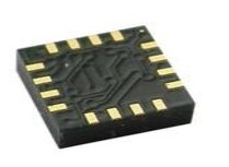
MCP25625 Pinout

MCP25625 Pinout
MCP25625 Description
The MCP25625 is a complete, cost-effective and small footprint CAN solution that can be easily added to a microcontroller with an available SPI interface.
The MCP25625 interfaces directly with microcontrollers operating at 2.7V to 5.5V; there are no external level shifters required. In addition, the MCP25625 connects directly to the physical CAN bus, supporting all requirements for CAN high-speed transceivers.
The MCP25625 meets the automotive requirements for high-speed (up to 1 Mb/s), low quiescent current, Electromagnetic Compatibility (EMC) and Electrostatic Discharge (ESD).
Specifications
- TypeParameter
Parts with Similar Specs
MCP25625 CAD Model
Symbol

MCP25625 Symbol
Footprint

MCP25625 Footprint
3D Model

MCP25625 3D Model
MCP25625 Feature
• Stand-Alone CAN 2.0B Controller with Integrated CAN Transceiver and Serial Peripheral Interface (SPI)
• Up to 1 Mb/s Operation
• Very Low Standby Current (10 µA, typical)
• Up to 10 MHz SPI Clock Speed
• Interfaces Directly with Microcontrollers with 2.7V to 5.5V I/Os
• Available in SSOP-28L and 6x6 QFN-28L
• Temperature Ranges:
- Extended (E): -40°C to +125°C
MCP25625 Applications
Automotive
Communications & Networking
MCP25625 Block Diagram

MCP25625 Block Diagram
MCP25625 Typical Application Circuit
The circuit shows an example of a typical application of the MCP25625 below. In this example, the microcontroller operates at 3.3V. VDDA supplies the CAN transceiver and must be connected to 5V. VDD, VIO of the MCP25625 are connected to the VDD of the microcontroller.
The digital supply can range from 2.7V to 5.5V. Therefore, the I/O of the MCP25625 is connected directly to the microcontroller, no level shifters are required.
The TXD and RDX pins of the CAN transceiver must be externally connected to the TxCAN and Rx pins of the CAN controller.
The SPI interface is used to configure and control the CAN controller.
The INT pin of the MCP25625 signals an interrupts to the microcontroller. Interrupts need to be cleared by the microcontroller through SPI.
The usage of RxnBF and TxnRTS is optional since the functions of these pins can be accessed through SPI. The RESET pin can optionally be pulled up to the VDD of the MCP25625 using a 10 k resistor. The CLKOUT pin provides the clock to the microcontroller.

MCP25625 Typical Application Circuit
MCP25625 Mode of Operation
The CAN controller has five modes of operation:
• Configuration mode
• Normal mode
• Sleep mode
• Listen-Only mode
• Loopback mode
MCP25625 Package

MCP25625 Package
MCP25625 Manufacturer
Microchip Technology Inc., is a leader that provides microcontroller and analogue semiconductors. The microchip was headquartered in Chandler, Arizona. We are dedicated to offering low-risk product development, reducing total system cost and accelerating time to market. We mainly serve different fields of customers applications around the world. To provide prominent technical support along with reliable delivery and quality is our goal.
Popularity by Region
What is mcp25625?
The MCP25625 is a complete, cost-effective and small footprint CAN solution that can be easily added to a microcontroller with an available SPI interface. The MCP25625 interfaces directly with microcontrollers operating at 2.7V to 5.5V; there are no external level shifters required. In addition, the MCP25625 connects directly to the physical CAN bus, supporting all requirements for CAN high-speed transceivers. The MCP25625 meets the automotive requirements for high-speed (up to 1 Mb/s), low quiescent current, Electromagnetic Compatibility (EMC) and Electrostatic Discharge (ESD).
How many modes of operation does the MCP25625 have?
The CAN controller has five modes of operation: • Configuration mode • Normal mode • Sleep mode • Listen-Only mode • Loopback mode
What differences is between CAN transceiver and CAN controller?
The CAN transceiver and controller make up the CAN node. A CAN transceiver is an interface between the controller and the CAN bus. The transceiver translates the logic level messages from the controller into the CAN differential scheme on the CANH and CANL pins of the CAN transceiver.
 P5010 vs. P5020: What is the Difference
23 July 2021343
![74LS86 Quad 2-Input XOR Gate IC: Pin, Datasheet pdf and Circuit Using 7486 Gate [FAQ]](https://res.utmel.com/Images/Article/b86c4a92-48b3-4a15-9a39-0fbf4ed13c63.jpg) 74LS86 Quad 2-Input XOR Gate IC: Pin, Datasheet pdf and Circuit Using 7486 Gate [FAQ]
74LS86 Quad 2-Input XOR Gate IC: Pin, Datasheet pdf and Circuit Using 7486 Gate [FAQ]08 December 202115168
 MPSA56 Transistor: MPSA56, Equivalent, Datasheet
07 January 20229100
 MPL3115A2 Pressure Sensor: Datasheet, Pinout and Schematic
25 August 20212837
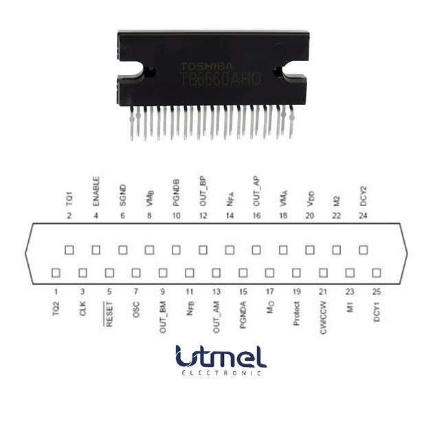 TB6560AHQ:PWM chopper-type stepping motor driver IC
17 April 20251471
 ATmega328P Series: 8-bit AVR Microcontroller Design Guide
15 January 2026448
 HMC5883L Digital Compass IC: Pinout, Datasheet and Alternatives
06 September 20213932
 TIP117 PNP Power Transistor: Datasheet pdf, STM Darlington transistor
21 December 20212577
 What is a Digital-to-analog Converter?
04 June 20243554
 Electronic components in a smart watch
15 May 20239318
 Huawei's Mysterious Advanced Chip in New Mate 60 Pro Smartphone Sparks Speculation Amid US Sanctions
01 September 20231870
 What is ARM Processor?
17 March 20224103
 How much do you know about CPU?
07 February 20222480
 Parking Access Control System using Arduino
29 August 20234320
 A Decade-Long Investment in ON Semiconductor Corp. Yields Over 1200% Returns
18 September 20232678
 What is an LDO (Low Dropout Regulator)?
29 October 20215580
In Stock
United States
China
Canada
Japan
Russia
Germany
United Kingdom
Singapore
Italy
Hong Kong(China)
Taiwan(China)
France
Korea
Mexico
Netherlands
Malaysia
Austria
Spain
Switzerland
Poland
Thailand
Vietnam
India
United Arab Emirates
Afghanistan
Åland Islands
Albania
Algeria
American Samoa
Andorra
Angola
Anguilla
Antigua & Barbuda
Argentina
Armenia
Aruba
Australia
Azerbaijan
Bahamas
Bahrain
Bangladesh
Barbados
Belarus
Belgium
Belize
Benin
Bermuda
Bhutan
Bolivia
Bonaire, Sint Eustatius and Saba
Bosnia & Herzegovina
Botswana
Brazil
British Indian Ocean Territory
British Virgin Islands
Brunei
Bulgaria
Burkina Faso
Burundi
Cabo Verde
Cambodia
Cameroon
Cayman Islands
Central African Republic
Chad
Chile
Christmas Island
Cocos (Keeling) Islands
Colombia
Comoros
Congo
Congo (DRC)
Cook Islands
Costa Rica
Côte d’Ivoire
Croatia
Cuba
Curaçao
Cyprus
Czechia
Denmark
Djibouti
Dominica
Dominican Republic
Ecuador
Egypt
El Salvador
Equatorial Guinea
Eritrea
Estonia
Eswatini
Ethiopia
Falkland Islands
Faroe Islands
Fiji
Finland
French Guiana
French Polynesia
Gabon
Gambia
Georgia
Ghana
Gibraltar
Greece
Greenland
Grenada
Guadeloupe
Guam
Guatemala
Guernsey
Guinea
Guinea-Bissau
Guyana
Haiti
Honduras
Hungary
Iceland
Indonesia
Iran
Iraq
Ireland
Isle of Man
Israel
Jamaica
Jersey
Jordan
Kazakhstan
Kenya
Kiribati
Kosovo
Kuwait
Kyrgyzstan
Laos
Latvia
Lebanon
Lesotho
Liberia
Libya
Liechtenstein
Lithuania
Luxembourg
Macao(China)
Madagascar
Malawi
Maldives
Mali
Malta
Marshall Islands
Martinique
Mauritania
Mauritius
Mayotte
Micronesia
Moldova
Monaco
Mongolia
Montenegro
Montserrat
Morocco
Mozambique
Myanmar
Namibia
Nauru
Nepal
New Caledonia
New Zealand
Nicaragua
Niger
Nigeria
Niue
Norfolk Island
North Korea
North Macedonia
Northern Mariana Islands
Norway
Oman
Pakistan
Palau
Palestinian Authority
Panama
Papua New Guinea
Paraguay
Peru
Philippines
Pitcairn Islands
Portugal
Puerto Rico
Qatar
Réunion
Romania
Rwanda
Samoa
San Marino
São Tomé & Príncipe
Saudi Arabia
Senegal
Serbia
Seychelles
Sierra Leone
Sint Maarten
Slovakia
Slovenia
Solomon Islands
Somalia
South Africa
South Sudan
Sri Lanka
St Helena, Ascension, Tristan da Cunha
St. Barthélemy
St. Kitts & Nevis
St. Lucia
St. Martin
St. Pierre & Miquelon
St. Vincent & Grenadines
Sudan
Suriname
Svalbard & Jan Mayen
Sweden
Syria
Tajikistan
Tanzania
Timor-Leste
Togo
Tokelau
Tonga
Trinidad & Tobago
Tunisia
Turkey
Turkmenistan
Turks & Caicos Islands
Tuvalu
U.S. Outlying Islands
U.S. Virgin Islands
Uganda
Ukraine
Uruguay
Uzbekistan
Vanuatu
Vatican City
Venezuela
Wallis & Futuna
Yemen
Zambia
Zimbabwe