
 Product
 Brand
Brand Articles
 Tools
Tools
PCF8575 I/O Expander : Pinout, Schematic and Datasheet

24 Termination 0.65mm 3/5V I/O Expander PCF8575 24 Pin 3.3V 24-TSSOP (0.173, 4.40mm Width)
Unit Price: $2.817136
Ext Price: $2.82


24 Termination 0.65mm 3/5V I/O Expander PCF8575 24 Pin 3.3V 24-TSSOP (0.173, 4.40mm Width)
Hello everyone, I welcome you to read my post today. After reading it, you will have a clear understanding about PCF8575. The PCF8575 is a remote16-BIT I2C and SMBus I/O expander with interrupt output. This article mainly introduce pinout, schematic, datasheet and other detailed information about Texas Instruments PCF8575.

Part1 - PCF8575 - I2C Remote 16 bit IO expander - ESP8266 Driver
PCF8575 Description
The PCF8575 is a remote16-BIT I2C and SMBus I/O expander with interrupt output. Which provides general-purpose remote I/O expansion for most microcontroller families by way of the I2C interface [serial clock (SCL), serial data (SDA)].
Including latched outputs with high-current drive capability for directly driving LEDs. Each quasi-bidirectional I/O can be used as an input or output without the use of a data-direction control signal.
At power on, the I/Os are high. In this mode, only a current source to VCC is active. On board 3.3V level converter circuit, if you donot solder VCC-VDD pad, the PCF8575 level is 3.3V. If you solder it, the level will be the same with VCC.
The module connects via the I2C bus to your microcontroller and offers I2C address selection by closing solder jumpers on the bottom side (base address is 0x20). You can either use it on 3.3V or 5V thanks to its on-board LDO and level shifter.
The VDD pin is the power supply for 5V, the VCC pin is the 3.3V output voltage of the LDO. If you use it as 5V device, you supply 5V on VDD. If you use it as 3.3V device, you supply 3.3V to the VCC pin and close the solder jumper VCC-VDD on the bottom side. In a mixed mode, with 5V GPIO ports but connected to a 3.3V microcontroller, you supply 5V to VDD but leave the VCC-VDD jumper open.
PCF8575 Pinout


PCF8575 CAD Model
Footprint

3D Model

PCF8575 Features
• Low Standby-Current Consumption of 10 µA Max
• I²C to Parallel-Port Expander
• Open-Drain Interrupt Output
• Compatible With Most Microcontrollers
• 400-kHz Fast I²C Bus
• Address by Three Hardware Address Pins for Use of up to Eight Devices
• Latched Outputs With High-Current Drive Capability for Directly Driving LEDs
• Current Source to VCC for Actively Driving a high at the output
• Latch-Up Performance Exceeds 100 mA Per JESD 78, Class II
• Working voltage: 2.5 - 5.5VDC
• Working current: 100mA(MAX)
• I²C address: 0x20(default),can be modified by soldering A1 and A2 selection pads.
• 16 individually addressable pins.
• Each pin configurable for input or output pin for input change interrupt.
• Arduino available library: PCF8575
• Suitable for Arduino UNO R3 and other MCU to control simple relay, buzzer, button, led.
• ESD Protection Exceeds JESD 22
– 2000-V Human-Body Model (A114-A)– 200-V Machine Model (A115-A)
– 1000-V Charged-Device Model (C101)
Specifications
- TypeParameter
- Lifecycle Status
Lifecycle Status refers to the current stage of an electronic component in its product life cycle, indicating whether it is active, obsolete, or transitioning between these states. An active status means the component is in production and available for purchase. An obsolete status indicates that the component is no longer being manufactured or supported, and manufacturers typically provide a limited time frame for support. Understanding the lifecycle status is crucial for design engineers to ensure continuity and reliability in their projects.
ACTIVE (Last Updated: 5 days ago) - Factory Lead Time6 Weeks
- Mounting Type
The "Mounting Type" in electronic components refers to the method used to attach or connect a component to a circuit board or other substrate, such as through-hole, surface-mount, or panel mount.
Surface Mount - Package / Case
refers to the protective housing that encases an electronic component, providing mechanical support, electrical connections, and thermal management.
24-TSSOP (0.173, 4.40mm Width) - Surface Mount
having leads that are designed to be soldered on the side of a circuit board that the body of the component is mounted on.
YES - Number of Pins24
- Weight89.499445mg
- Number of I/Os16
- Operating Temperature
The operating temperature is the range of ambient temperature within which a power supply, or any other electrical equipment, operate in. This ranges from a minimum operating temperature, to a peak or maximum operating temperature, outside which, the power supply may fail.
-40°C~85°C - Packaging
Semiconductor package is a carrier / shell used to contain and cover one or more semiconductor components or integrated circuits. The material of the shell can be metal, plastic, glass or ceramic.
Tube - JESD-609 Code
The "JESD-609 Code" in electronic components refers to a standardized marking code that indicates the lead-free solder composition and finish of electronic components for compliance with environmental regulations.
e4 - Pbfree Code
The "Pbfree Code" parameter in electronic components refers to the code or marking used to indicate that the component is lead-free. Lead (Pb) is a toxic substance that has been widely used in electronic components for many years, but due to environmental concerns, there has been a shift towards lead-free alternatives. The Pbfree Code helps manufacturers and users easily identify components that do not contain lead, ensuring compliance with regulations and promoting environmentally friendly practices. It is important to pay attention to the Pbfree Code when selecting electronic components to ensure they meet the necessary requirements for lead-free applications.
yes - Part Status
Parts can have many statuses as they progress through the configuration, analysis, review, and approval stages.
Active - Moisture Sensitivity Level (MSL)
Moisture Sensitivity Level (MSL) is a standardized rating that indicates the susceptibility of electronic components, particularly semiconductors, to moisture-induced damage during storage and the soldering process, defining the allowable exposure time to ambient conditions before they require special handling or baking to prevent failures
1 (Unlimited) - Number of Terminations24
- ECCN Code
An ECCN (Export Control Classification Number) is an alphanumeric code used by the U.S. Bureau of Industry and Security to identify and categorize electronic components and other dual-use items that may require an export license based on their technical characteristics and potential for military use.
EAR99 - Terminal Finish
Terminal Finish refers to the surface treatment applied to the terminals or leads of electronic components to enhance their performance and longevity. It can improve solderability, corrosion resistance, and overall reliability of the connection in electronic assemblies. Common finishes include nickel, gold, and tin, each possessing distinct properties suitable for various applications. The choice of terminal finish can significantly impact the durability and effectiveness of electronic devices.
Nickel/Palladium/Gold (Ni/Pd/Au) - HTS Code
HTS (Harmonized Tariff Schedule) codes are product classification codes between 8-1 digits. The first six digits are an HS code, and the countries of import assign the subsequent digits to provide additional classification. U.S. HTS codes are 1 digits and are administered by the U.S. International Trade Commission.
8542.39.00.01 - Voltage - Supply
Voltage - Supply refers to the range of voltage levels that an electronic component or circuit is designed to operate with. It indicates the minimum and maximum supply voltage that can be applied for the device to function properly. Providing supply voltages outside this range can lead to malfunction, damage, or reduced performance. This parameter is critical for ensuring compatibility between different components in a circuit.
4.5V~5.5V - Terminal Position
In electronic components, the term "Terminal Position" refers to the physical location of the connection points on the component where external electrical connections can be made. These connection points, known as terminals, are typically used to attach wires, leads, or other components to the main body of the electronic component. The terminal position is important for ensuring proper connectivity and functionality of the component within a circuit. It is often specified in technical datasheets or component specifications to help designers and engineers understand how to properly integrate the component into their circuit designs.
DUAL - Terminal Form
Occurring at or forming the end of a series, succession, or the like; closing; concluding.
GULL WING - Peak Reflow Temperature (Cel)
Peak Reflow Temperature (Cel) is a parameter that specifies the maximum temperature at which an electronic component can be exposed during the reflow soldering process. Reflow soldering is a common method used to attach electronic components to a circuit board. The Peak Reflow Temperature is crucial because it ensures that the component is not damaged or degraded during the soldering process. Exceeding the specified Peak Reflow Temperature can lead to issues such as component failure, reduced performance, or even permanent damage to the component. It is important for manufacturers and assemblers to adhere to the recommended Peak Reflow Temperature to ensure the reliability and functionality of the electronic components.
260 - Supply Voltage
Supply voltage refers to the electrical potential difference provided to an electronic component or circuit. It is crucial for the proper operation of devices, as it powers their functions and determines performance characteristics. The supply voltage must be within specified limits to ensure reliability and prevent damage to components. Different electronic devices have specific supply voltage requirements, which can vary widely depending on their design and intended application.
3.3V - Terminal Pitch
The center distance from one pole to the next.
0.65mm - Base Part Number
The "Base Part Number" (BPN) in electronic components serves a similar purpose to the "Base Product Number." It refers to the primary identifier for a component that captures the essential characteristics shared by a group of similar components. The BPN provides a fundamental way to reference a family or series of components without specifying all the variations and specific details.
PCF8575 - Pin Count
a count of all of the component leads (or pins)
24 - Number of Outputs16
- Output Type
The "Output Type" parameter in electronic components refers to the type of signal or data that is produced by the component as an output. This parameter specifies the nature of the output signal, such as analog or digital, and can also include details about the voltage levels, current levels, frequency, and other characteristics of the output signal. Understanding the output type of a component is crucial for ensuring compatibility with other components in a circuit or system, as well as for determining how the output signal can be utilized or processed further. In summary, the output type parameter provides essential information about the nature of the signal that is generated by the electronic component as its output.
Push-Pull - Operating Supply Voltage
The voltage level by which an electrical system is designated and to which certain operating characteristics of the system are related.
5.5V - Power Supplies
an electronic circuit that converts the voltage of an alternating current (AC) into a direct current (DC) voltage.?
3/5V - Interface
In electronic components, the term "Interface" refers to the point at which two different systems, devices, or components connect and interact with each other. It can involve physical connections such as ports, connectors, or cables, as well as communication protocols and standards that facilitate the exchange of data or signals between the connected entities. The interface serves as a bridge that enables seamless communication and interoperability between different parts of a system or between different systems altogether. Designing a reliable and efficient interface is crucial in ensuring proper functionality and performance of electronic components and systems.
I2C, SMBus - Number of Ports
A port is identified for each transport protocol and address combination by a 16-bit unsigned number,.
2 - Number of Bits16
- Clock Frequency
Clock frequency, also known as clock speed, refers to the rate at which a processor or electronic component can execute instructions. It is measured in hertz (Hz) and represents the number of cycles per second that the component can perform. A higher clock frequency typically indicates a faster processing speed and better performance. However, it is important to note that other factors such as architecture, efficiency, and workload also play a significant role in determining the overall performance of a component. In summary, clock frequency is a crucial parameter that influences the speed and efficiency of electronic components in processing data and executing tasks.
400kHz - Supply Current-Max
Supply Current-Max refers to the maximum amount of current that an electronic component or circuit can draw from its power supply under specified operating conditions. It is a critical parameter that determines the power consumption and thermal performance of the device. Exceeding this limit can lead to overheating, potential damage, or failure of the component. Knowing the Supply Current-Max helps in designing circuits that ensure proper operation and reliability.
0.2mA - Interrupt Output
In electronic components, "Interrupt Output" refers to a feature that allows a device to signal the occurrence of a specific event or condition that requires immediate attention from the system or user. When the specified event occurs, the interrupt output generates a signal to pause the normal operation of the device and divert the attention to handle the urgent task. This feature is commonly used in microcontrollers, processors, and other integrated circuits to efficiently manage tasks and prioritize critical operations. By utilizing interrupt outputs, electronic systems can respond promptly to important events, improve overall performance, and enhance real-time responsiveness.
Yes - Current - Output Source/Sink
The parameter "Current - Output Source/Sink" in electronic components refers to the maximum amount of current that the component can either source (provide) or sink (absorb) at its output pin. This parameter is crucial in determining the capability of the component to drive external loads such as other components or devices. The source current indicates the maximum current that the component can supply to the load, while the sink current indicates the maximum current that the component can draw from the load. Understanding this parameter is essential for designing circuits that require specific current-handling capabilities to ensure proper functionality and reliability.
10mA 25mA - Features
In the context of electronic components, the term "Features" typically refers to the specific characteristics or functionalities that a particular component offers. These features can vary depending on the type of component and its intended use. For example, a microcontroller may have features such as built-in memory, analog-to-digital converters, and communication interfaces like UART or SPI.When evaluating electronic components, understanding their features is crucial in determining whether they meet the requirements of a particular project or application. Engineers and designers often look at features such as operating voltage, speed, power consumption, and communication protocols to ensure compatibility and optimal performance.In summary, the "Features" parameter in electronic components describes the unique attributes and capabilities that differentiate one component from another, helping users make informed decisions when selecting components for their electronic designs.
POR - Height1.2mm
- Length7.8mm
- Width4.4mm
- Thickness
Thickness in electronic components refers to the measurement of how thick a particular material or layer is within the component structure. It can pertain to various aspects, such as the thickness of a substrate, a dielectric layer, or conductive traces. This parameter is crucial as it impacts the electrical, mechanical, and thermal properties of the component, influencing its performance and reliability in electronic circuits.
1mm - Radiation Hardening
Radiation hardening is the process of making electronic components and circuits resistant to damage or malfunction caused by high levels of ionizing radiation, especially for environments in outer space (especially beyond the low Earth orbit), around nuclear reactors and particle accelerators, or during nuclear accidents or nuclear warfare.
No - RoHS Status
RoHS means “Restriction of Certain Hazardous Substances” in the “Hazardous Substances Directive” in electrical and electronic equipment.
ROHS3 Compliant - Lead Free
Lead Free is a term used to describe electronic components that do not contain lead as part of their composition. Lead is a toxic material that can have harmful effects on human health and the environment, so the electronics industry has been moving towards lead-free components to reduce these risks. Lead-free components are typically made using alternative materials such as silver, copper, and tin. Manufacturers must comply with regulations such as the Restriction of Hazardous Substances (RoHS) directive to ensure that their products are lead-free and environmentally friendly.
Lead Free
PCF8575 Simplified Schematic

PCF8575 Alternative

PCF8575 Application Schematic

PCF8575 Logic Diagram
.png")
PCF8575 Layout Example

PCF8575 Applications
●Used in Telecom Shelters: Filter Units
●Used in Servers
●Used in Routers (Telecom Switching Equipment)
●Used in Personal Computers
●Used in Personal Electronics
●Used in Industrial Automation
●Used in Products with GPIO-Limited Processors
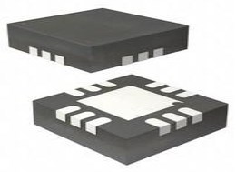
PCF8575 Package

PCF8575 Manufacturer
Texas Instruments (TI) is an American technology company headquartered in Dallas, Texas, which designs and manufactures semiconductors and various integrated circuits, and sells them to electronic designers and manufacturers worldwide. It is one of the top 10 semiconductor companies in global sales. The company focuses on the development of analog chips and embedded processors, which account for more than 80% of its revenue. TI also produces TI digital light processing technology and educational technology products, including calculators, microcontrollers and multi-core processors. As of 2016, the company has 45,000 patents worldwide.
Trend Analysis
Datasheet PDF
- PCN Design/Specification :
 ADG1204 Multiplexer: Pinout, Features and Datasheet
14 February 20221405
 Microchip dsPIC33EP256GP502IMM: Advanced Features and Applications Overview
29 February 2024304
 AD9508 1.65 GHz Clock Buffer: Datasheet, Ultra-Low Jitter Specs, and Configuration Analysis
21 April 2026259
 MIC4452YN IC GATE DRVR LOW-SIDE 8DIP: Datasheet, Pinout, and Equivalents
14 February 20221607
 LM1084 Positive Regulators : Price, Application and Circuit
31 July 20213666
 1N4742A Zener Diodes: Features, Pinout, and Datasheet
18 October 20218898
 LM3671MF-2.8 DC-DC converter: Pinout, Specification, and Datasheet
24 June 20212029
 IRLML6402 Transistor: Features, Pinout, and Datasheet
07 October 20216733
 Diodes Tutorial: How to Test Diodes?
22 October 202511143
 What is GND in a Circuit?
18 December 202547313
 Toggle Switches: Features, Types and Applications
23 January 202111118
 Exploring the Strengths and Hurdles of Wide Bandgap Devices in Alternating Current Electric Drives
19 January 20243619
 How to Address IoT Eco-security in the Era of Digital Transformation?
22 April 2022594
 Introduction to TVS Diodes
07 August 202013714
 Semiconductor Equipment Industry Research
25 March 20244920
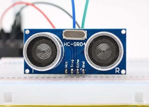 All You Need to Know about Ultrasonic Sensors
25 October 202512380
Texas Instruments
In Stock: 2000
Minimum: 1 Multiples: 1
Qty
Unit Price
Ext Price
1
$2.817136
$2.82
10
$2.657675
$26.58
100
$2.507241
$250.72
500
$2.365322
$1,182.66
1000
$2.231436
$2,231.44
Not the price you want? Send RFQ Now and we'll contact you ASAP.
Inquire for More Quantity
![PCA9555DWR]() PCA9555DWR
PCA9555DWRTexas Instruments
![TCA6424ARGJR]() TCA6424ARGJR
TCA6424ARGJRTexas Instruments
![PCF8574ADW]() PCF8574ADW
PCF8574ADWTexas Instruments
![PCA9557PWR]() PCA9557PWR
PCA9557PWRTexas Instruments
![TCA6408ARSVR]() TCA6408ARSVR
TCA6408ARSVRTexas Instruments
![PCA9536DGKR]() PCA9536DGKR
PCA9536DGKRTexas Instruments
![PCA9555PWR]() PCA9555PWR
PCA9555PWRTexas Instruments
![TCA9555RTWR]() TCA9555RTWR
TCA9555RTWRTexas Instruments
![PCA9535RGER]() PCA9535RGER
PCA9535RGERTexas Instruments
![PCF8574DWR]() PCF8574DWR
PCF8574DWRTexas Instruments


