
 Product
 Brand
Brand Articles
 Tools
Tools
SI4463 Transceiver: Features, Pinout, and Datasheet

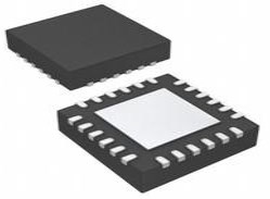
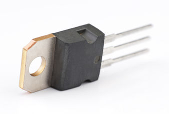
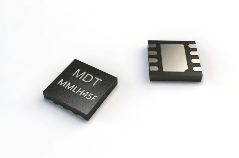
TxRx + MCU 142MHz~1.05GHz 1.8V~3.6V SPI 1Mbps 10.9mA~13.7mA - Receiving 44.5mA~88mA - Transmitting 4GFSK, GFSK, GMSK, OOK 4 20-VFQFN Exposed Pad


TxRx + MCU 142MHz~1.05GHz 1.8V~3.6V SPI 1Mbps 10.9mA~13.7mA - Receiving 44.5mA~88mA - Transmitting 4GFSK, GFSK, GMSK, OOK 4 20-VFQFN Exposed Pad
Silicon Laboratories' SI4463 devices are high-performance, low-current transceivers covering the sub-GHz frequency bands from 142 to 1050 MHz. This article mainly introduces features, pinout, datasheet and other detailed information about Silicon Labs SI4463.
SI4463 Description
Silicon Laboratories' SI4463 devices are high-performance, low-current transceivers covering the sub-GHz frequency bands from 142 to 1050 MHz. The radios are part of the EZRadioPRO® family, which includes a complete line of transmitters, receivers, and transceivers covering a wide range of applications. All parts offer outstanding sensitivity of –129 dBm while achieving extremely low active and standby current consumption.
The SI4463 offers frequency coverage in all major bands, including optimal phase noise, blocking, and selectivity performance for narrowband and wireless MBus licensed band applications, such as FCC Part90 and 169 MHz wireless Mbus. The 69 dB adjacent channel selectivity with 12.5 kHz channel spacing ensures robust receive operation in harsh RF conditions, which is particularly important for narrowband operation. The SI4463 offers exceptional output power of up to +20 dBm with outstanding TX efficiency. The high output power and sensitivity result in an industry-leading link budget of 146 dB allowing extended ranges and highly robust communication links. The SI4463 can achieve up to +27 dBm output power with built-in ramping control of a low-cost external FET.
The devices can meet worldwide regulatory standards: FCC, ETSI, wireless MBus, and ARIB. All devices are designed to be compliant with 802.15.4g and WMbus smart metering standards. The devices are highly flexible and can be configured via the Wireless Development Suite (WDS) available on the Silicon Labs website.
SI4463 Pinout

Pinout
| Pin Number | Pin Name | I/O | Description |
| 1 | SDN | I | Shutdown Input Pin. 0–VDD V digital input. SDN should be = 0 in all modes except Shutdown mode. When SDN = 1, the chip will be completely shut down, and the contents of the registers will be lost. |
| 2 | RXp | I | Differential RF Input Pins of the LNA. See application schematic for example matching network. |
| 3 | RXn | I | |
| 4 | TX | O | Transmit Output Pin. The PA output is an open-drain connection, so the L-C match must supply VDD (+3.3 VDC nominal) to this pin. |
| 5 | NC | It is recommended to connect this pin to GND per the reference design schematic. Not connected internally to any circuitry. | |
| 6 | VDD | VDD | +1.8 to +3.8 V Supply Voltage Input to Internal Regulators. The recommended VDD supply voltage is +3.3 V. |
| 7 | TXRAMP | O | Programmable Bias Output with Ramp Capability for External FET PA. |
| 8 | VDD | VDD | +1.8 to +3.8 V Supply Voltage Input to Internal Regulators. The recommended VDD supply voltage is +3.3 V. |
| 9 | GPIO0 | I/O | General Purpose Digital I/O. May be configured through the registers to perform various functions including: Microcontroller Clock Output, FIFO status, POR, Wake-Up timer, Low Battery Detect, TRSW, AntDiversity control, etc. |
| 10 | GPIO1 | I/O | |
| 11 | nIRQ | O | General Microcontroller Interrupt Status Output. When the SI4463 exhibits any one of the interrupt events, the nIRQ pin will be set low = 0. The Microcontroller can then determine the state of the interrupt by reading the interrupt status. No external resistor pull-up is required, but it may be desirable if multiple interrupt lines are connected. |
| 12 | SCLK | I | Serial Clock Input. 0–VDD V digital input. This pin provides the serial data clock function for the 4-line serial data bus. Data is clocked into the SI4463 on positive edge transitions. |
| 13 | SDO | O | 0–VDD V Digital Output. Provides a serial readback function of the internal control registers. |
| 14 | SDI | I | Serial Data Input. 0–VDD V digital input. This pin provides the serial data stream for the 4-line serial data bus. |
| 15 | nSEL | I | Serial Interface Select Input. 0–VDD V digital input. This pin provides the Select/Enable function for the 4-line serial data bus. |
| 16 | XOUT | O | Crystal Oscillator Output. Connect to an external 25 to 32 MHz crystal, or leave floating when driving with an external source on XIN. |
| 17 | XIN | I | Crystal Oscillator Input. Connect to an external 25 to 32 MHz crystal, or connect to an external source. |
| 18 | GND | GND | When using an XTAL, leave floating per the reference design schematic. When using a TCXO, connect to TCXO GND, which should be separate from the board’s reference ground plane. |
| 19 | GPIO2 | I/O | General Purpose Digital I/O. May be configured through the registers to perform various functions, including Microcontroller Clock Output, FIFO status, POR, Wake-Up timer, Low Battery Detect, TRSW, AntDiversity control, etc. |
| 20 | GPIO3 | I/O | |
| PKG | PADDLE_GND | GND | The exposed metal paddle on the bottom of the SI4463 supplies the RF and circuit ground(s) for the entire chip. It is very important that a good solder connection is made between this exposed metal paddle and the ground plane of the PCB underlying the SI4463. |
SI4463 CAD Model

Symbol

Footprint

3D Model
SI4463 Features
● Frequency range = 142–1050 MHz
● Receive sensitivity = –129 dBm
● Modulation
--(G)FSK, 4(G)FSK, (G)MSK
--OOK
● Max output power
--+20 dBm (Si4463)
--+16 dBm (Si4461)
--+13 dBm (Si4460)
● PA support for +27 or +30 dBm
● Low active power consumption
--10/13 mA RX
--18 mA TX at +10 dBm (Si4460)
● Ultra-low current power down modes
--30 nA shutdown, 40 nA standby
● Preamble sense mode
--6 mA average RX current at 1.2 kbps
--10 µA average RX current at 50 kbps and 1-sec sleep interval
● Fast preamble detection
--1 byte preamble detection
● Data rate = 100 bps to 1 Mbps
● Fast wake and hop times
● Power supply = 1.8 to 3.8 V
● Excellent selectivity performance
--69 dB adjacent channel
--79 dB blocking at 1 MHz
● Antenna diversity and T/R switch control
● The highly configurable packet handler
● TX and RX 64 byte FIFOs
--129 bytes dedicated Tx or Rx
● Auto frequency control (AFC)
● Automatic gain control (AGC)
● Low BOM
● Low battery detector
● Temperature sensor
● 20-Pin QFN package
● IEEE 802.15.4g and WMBus compliant
● Suitable for FCC Part 90 Mask D, FCC part 15.247, 15,231, 15,249, ARIB T-108, T-96, T-67, RCR STD-30, China regulatory
● ETSI Category I Operation EN300 220
Specifications
- TypeParameter
- Factory Lead Time8 Weeks
- Contact Plating
Contact plating (finish) provides corrosion protection for base metals and optimizes the mechanical and electrical properties of the contact interfaces.
Tin - Mount
In electronic components, the term "Mount" typically refers to the method or process of physically attaching or fixing a component onto a circuit board or other electronic device. This can involve soldering, adhesive bonding, or other techniques to secure the component in place. The mounting process is crucial for ensuring proper electrical connections and mechanical stability within the electronic system. Different components may have specific mounting requirements based on their size, shape, and function, and manufacturers provide guidelines for proper mounting procedures to ensure optimal performance and reliability of the electronic device.
Surface Mount - Mounting Type
The "Mounting Type" in electronic components refers to the method used to attach or connect a component to a circuit board or other substrate, such as through-hole, surface-mount, or panel mount.
Surface Mount - Package / Case
refers to the protective housing that encases an electronic component, providing mechanical support, electrical connections, and thermal management.
20-VFQFN Exposed Pad - Operating Temperature
The operating temperature is the range of ambient temperature within which a power supply, or any other electrical equipment, operate in. This ranges from a minimum operating temperature, to a peak or maximum operating temperature, outside which, the power supply may fail.
-40°C~85°C - Packaging
Semiconductor package is a carrier / shell used to contain and cover one or more semiconductor components or integrated circuits. The material of the shell can be metal, plastic, glass or ceramic.
Tape & Reel (TR) - Published2011
- Part Status
Parts can have many statuses as they progress through the configuration, analysis, review, and approval stages.
Active - Moisture Sensitivity Level (MSL)
Moisture Sensitivity Level (MSL) is a standardized rating that indicates the susceptibility of electronic components, particularly semiconductors, to moisture-induced damage during storage and the soldering process, defining the allowable exposure time to ambient conditions before they require special handling or baking to prevent failures
1 (Unlimited) - Number of Terminations20
- TypeTxRx + MCU
- Voltage - Supply
Voltage - Supply refers to the range of voltage levels that an electronic component or circuit is designed to operate with. It indicates the minimum and maximum supply voltage that can be applied for the device to function properly. Providing supply voltages outside this range can lead to malfunction, damage, or reduced performance. This parameter is critical for ensuring compatibility between different components in a circuit.
1.8V~3.6V - Terminal Position
In electronic components, the term "Terminal Position" refers to the physical location of the connection points on the component where external electrical connections can be made. These connection points, known as terminals, are typically used to attach wires, leads, or other components to the main body of the electronic component. The terminal position is important for ensuring proper connectivity and functionality of the component within a circuit. It is often specified in technical datasheets or component specifications to help designers and engineers understand how to properly integrate the component into their circuit designs.
QUAD - Terminal Form
Occurring at or forming the end of a series, succession, or the like; closing; concluding.
NO LEAD - Peak Reflow Temperature (Cel)
Peak Reflow Temperature (Cel) is a parameter that specifies the maximum temperature at which an electronic component can be exposed during the reflow soldering process. Reflow soldering is a common method used to attach electronic components to a circuit board. The Peak Reflow Temperature is crucial because it ensures that the component is not damaged or degraded during the soldering process. Exceeding the specified Peak Reflow Temperature can lead to issues such as component failure, reduced performance, or even permanent damage to the component. It is important for manufacturers and assemblers to adhere to the recommended Peak Reflow Temperature to ensure the reliability and functionality of the electronic components.
NOT SPECIFIED - Number of Functions1
- Supply Voltage
Supply voltage refers to the electrical potential difference provided to an electronic component or circuit. It is crucial for the proper operation of devices, as it powers their functions and determines performance characteristics. The supply voltage must be within specified limits to ensure reliability and prevent damage to components. Different electronic devices have specific supply voltage requirements, which can vary widely depending on their design and intended application.
3.3V - Terminal Pitch
The center distance from one pole to the next.
0.5mm - Frequency
In electronic components, the parameter "Frequency" refers to the rate at which a signal oscillates or cycles within a given period of time. It is typically measured in Hertz (Hz) and represents how many times a signal completes a full cycle in one second. Frequency is a crucial aspect in electronic components as it determines the behavior and performance of various devices such as oscillators, filters, and communication systems. Understanding the frequency characteristics of components is essential for designing and analyzing electronic circuits to ensure proper functionality and compatibility with other components in a system.
142MHz~1.05GHz - Time@Peak Reflow Temperature-Max (s)
Time@Peak Reflow Temperature-Max (s) refers to the maximum duration that an electronic component can be exposed to the peak reflow temperature during the soldering process, which is crucial for ensuring reliable solder joint formation without damaging the component.
NOT SPECIFIED - JESD-30 Code
JESD-30 Code refers to a standardized descriptive designation system established by JEDEC for semiconductor-device packages. This system provides a systematic method for generating designators that convey essential information about the package's physical characteristics, such as size and shape, which aids in component identification and selection. By using JESD-30 codes, manufacturers and engineers can ensure consistency and clarity in the specification of semiconductor packages across various applications and industries.
S-XQCC-N20 - Operating Supply Voltage
The voltage level by which an electrical system is designated and to which certain operating characteristics of the system are related.
3.3V - Power - Output
Power Output in electronic components refers to the amount of electrical power that a device can deliver to a load. It is typically measured in watts and indicates the effectiveness of the component in converting electrical energy into usable work or signal. Power Output can vary based on the component's design, operating conditions, and intended application, making it a critical factor in the performance of amplifiers, power supplies, and other electronic devices. Understanding the Power Output helps in selecting appropriate components for specific applications to ensure efficiency and reliability.
20dBm Max - RF Family/Standard
The parameter "RF Family/Standard" in electronic components refers to the specific radio frequency (RF) technology or standard that the component complies with or is designed for. RF technology encompasses a wide range of frequencies used for wireless communication, such as Wi-Fi, Bluetooth, cellular networks, and more. Different RF standards dictate the frequency bands, modulation techniques, data rates, and other specifications for communication systems. Understanding the RF family/standard of a component is crucial for ensuring compatibility and optimal performance in RF applications.
General ISM < 1GHz - Data Rate (Max)
Data Rate (Max) refers to the maximum rate at which data can be transferred or processed within an electronic component or device. It is typically measured in bits per second (bps) or megabits per second (Mbps). This parameter is important for determining the speed and efficiency of data transmission or processing in various electronic applications such as computer systems, networking devices, and memory modules. A higher data rate indicates that the component is capable of handling larger volumes of data at a faster pace, leading to improved performance and responsiveness in electronic systems. It is crucial to consider the Data Rate (Max) specification when selecting electronic components to ensure compatibility and optimal functionality for specific applications.
1Mbps - Serial Interfaces
A serial interface is a communication interface between two digital systems that transmits data as a series of voltage pulses down a wire. Essentially, the serial interface encodes the bits of a binary number by their "temporal" location on a wire rather than their "spatial" location within a set of wires.
SPI - Current - Receiving
Current - Receiving refers to the amount of electrical current that an electronic component or device is capable of accepting from a power source or another component in a circuit. It indicates the maximum current that can be safely received without causing damage or malfunction. This parameter is crucial for ensuring compatibility and reliability in electronic designs, as exceeding the rated receiving current can lead to overheating or failure of the component.
10.9mA~13.7mA - Current - Transmitting
Current - Transmitting is a parameter used to describe the maximum amount of electrical current that an electronic component can handle while in the transmitting mode. This parameter is crucial for components such as transistors, diodes, and integrated circuits that are involved in transmitting signals or power within a circuit. Exceeding the specified current transmitting rating can lead to overheating, component failure, or even damage to the entire circuit. Designers and engineers must carefully consider this parameter when selecting components to ensure the reliability and performance of the electronic system.
44.5mA~88mA - Modulation
In electronic components, modulation refers to the process of varying one or more properties of a periodic waveform, known as the carrier signal, in order to encode information. This modulation technique is commonly used in communication systems to transmit data efficiently over long distances. By modulating the carrier signal, information such as audio, video, or data can be embedded onto the signal for transmission and then demodulated at the receiving end to retrieve the original information. There are various types of modulation techniques, including amplitude modulation (AM), frequency modulation (FM), and phase modulation (PM), each with its own advantages and applications in different communication systems.
4GFSK, GFSK, GMSK, OOK - Sensitivity (dBm)
Sensitivity (dBm) is a parameter used to measure the minimum input power level required for an electronic component or device to operate effectively. It is typically expressed in decibels relative to one milliwatt (dBm), which is a common unit of power measurement in the field of electronics. A higher sensitivity value indicates that the component can detect weaker input signals, making it more responsive and capable of functioning in low-power conditions. Sensitivity is an important specification for devices like receivers, sensors, and transducers, as it directly impacts their ability to detect and process signals accurately. Manufacturers often provide sensitivity ratings to help users understand the performance capabilities of the component in different operating conditions.
-129 dBm - GPIO
GPIO stands for General Purpose Input/Output. It is a type of electronic pin found on microcontrollers, microprocessors, and other integrated circuits that can be configured to either input or output digital signals. GPIO pins can be used to connect and communicate with external devices such as sensors, LEDs, motors, and more. They provide a flexible way to interact with the physical world by allowing the device to both receive and send digital signals. GPIO pins can be programmed and controlled by software to perform various functions based on the specific requirements of the electronic system.
4 - Height Seated (Max)
Height Seated (Max) is a parameter in electronic components that refers to the maximum allowable height of the component when it is properly seated or installed on a circuit board or within an enclosure. This specification is crucial for ensuring proper fit and alignment within the overall system design. Exceeding the maximum seated height can lead to mechanical interference, electrical shorts, or other issues that may impact the performance and reliability of the electronic device. Manufacturers provide this information to help designers and engineers select components that will fit within the designated space and function correctly in the intended application.
0.9mm - RoHS Status
RoHS means “Restriction of Certain Hazardous Substances” in the “Hazardous Substances Directive” in electrical and electronic equipment.
RoHS Compliant
SI4463 Functional Block Diagram

Functional Block Diagram
SI4463 Single Antenna with RF Switch Example

SI4463 Single Antenna with RF Switch Example
SI4463 Alternatives
| Part Number | Description | Manufacturer |
| 3D3523-10TELECOMMUNICATION CIRCUITS | Manchester Encoder/Decoder, CMOS, PDIP14, 0.300 INCH, ROHS COMPLIANT, DIP-14 | Data Delay Devices Inc |
| 3D3523D-50TELECOMMUNICATION CIRCUITS | Manchester Encoder/Decoder, CMOS, PDSO14, 0.150 INCH, ROHS COMPLIANT, SOIC-14 | Data Delay Devices Inc |
| 3D3523D-1TELECOMMUNICATION CIRCUITS | Manchester Encoder/Decoder, CMOS, PDSO14, 0.150 INCH, ROHS COMPLIANT, SOIC-14 | Data Delay Devices Inc |
| 3D3523G-25TELECOMMUNICATION CIRCUITS | Manchester Encoder/Decoder, CMOS, PDSO14, 0.300 INCH, ROHS COMPLIANT, GULLWING, DIP-14 | Data Delay Devices Inc |
| 3D3523D-25TELECOMMUNICATION CIRCUITS | Manchester Encoder/Decoder, CMOS, PDSO14, 0.150 INCH, ROHS COMPLIANT, SOIC-14 | Data Delay Devices Inc |
| SX1236IMLTRTTELECOMMUNICATION CIRCUITS | Manchester Encoder/Decoder, 6 X 6 MM, HALOGEN FREE AND ROHS COMPLIANT, QFN-28 | Semtech Corporation |
| 3D3523D-10TELECOMMUNICATION CIRCUITS | Manchester Encoder/Decoder, CMOS, PDSO14, 0.150 INCH, ROHS COMPLIANT, SOIC-14 | Data Delay Devices Inc |
| 3D3523G-50TELECOMMUNICATION CIRCUITS | Manchester Encoder/Decoder, CMOS, PDSO14, 0.300 INCH, ROHS COMPLIANT, GULLWING, DIP-14 | Data Delay Devices Inc |
| TDA5340TELECOMMUNICATION CIRCUITS | Manchester Encoder/Decoder, PDSO20, GREEN, PLASTIC, TSSOP-28 | Infineon Technologies AG |
| 3D3523-50TELECOMMUNICATION CIRCUITS | Manchester Encoder/Decoder, CMOS, PDIP14, 0.300 INCH, ROHS COMPLIANT, DIP-14 | Data Delay Devices Inc |
SI4463 Applications
● Smart Metering (802.15.4g and WMBus)
● Remote Control
● Home Security and Alarm
● Telemetry
● Garage and Gate Openers
● Remote Keyless Entry
● Home Automation
● Industrial Control
● Sensor Networks
● Health Monitors
● Electronic Shelf Labels
SI4463 Package

Package
SI4463 Manufacturer
Silicon Labs (NASDAQ: SLAB) is a leader in secure, intelligent wireless technology for a more connected world. They offer a broad product portfolio covering chips, software and system solutions for the Internet of Things, Internet infrastructure, industrial control, consumer and automotive markets. These solutions are used to solve the most difficult problems in the electronics industry and provide products with high performance, low energy consumption, simple design, and connectivity, enabling designers to transform their initial ideas into final products.
Their integrated hardware and software platform, intuitive development tools, unmatched ecosystem and robust support make them the ideal long-term partner in building advanced industrial, commercial, home and life applications. Silicon Labs make it easy for developers to solve complex wireless challenges throughout the product lifecycle and get to market quickly with innovative solutions that transform industries, grow economies and improve lives.
Datasheet PDF
- Datasheets :
1.What is the difference between SI4432 and SI4463 programming?
SI4463, as the follow-up model of SI4432 launched by Silabs, has done a more complete optimization of the latter's radio frequency performance and communication functions. In the communication function (SPI), the support for Silabs "EZRadioPRO" is mainly increased, and the API method is used to operate Si4463 for the first time, which is quite different from the direct register operation method of SI4432.
2.Are SI4463 and SI4438 registers common?
The SI4438 chip is still better than the 4432 performance index.
3.How does STM32 receive SI4463 data?
Just enter the parameters in the gray grid of the above picture, and then configure according to the generated data.
 Footprint of STM8S103K3T6C Microcontroller
24 July 2025199
 STM32L021K4T6 Ultra-Low-Power 32-bit MCU: Datasheet Analysis
29 February 2024163
 TCA9555RTWR Low-Voltage I/O Expander: Features, Applications and datasheet
07 January 20221039
 LM7806 Regulator: Pinout, Advantage and Datasheet
28 August 20216660
 ATMEGA328P Microcontroller: Pinout, Datasheet and Application
07 July 202110548
 megaAVR® 0-series 20MHz 8-bit MCU: Datasheet, UPDI, and Performance Deep Dive
06 February 202668
 SN65HVD1781DR Transceiver: Circuit, RS-485
28 March 20221916
 onsemi MJE15032G Review for Advanced Frequency Applications
08 September 2025272
 Introduction to Tantalum Capacitors
16 October 202511694
 Top 10 Technology Trends in the Global Semiconductor Industry in 2022
08 January 20228801
 Working Principle and Development of Magnetic Sensors
31 October 20253897
 Effect Of Target Physical Properties And Energetic Ions When Doping Thin-Body Semiconductor
19 October 20222417
 Shift Registers Made Simple for New Learners
15 July 20251448
 Facial Recognition: Features, Working and Applications
02 September 20218979
 Demand for Automotive Chips Will Surge 300%
09 April 20225173
 What are Programmable Logic Controllers?
07 September 20202949
Silicon Labs
In Stock: 5000
United States
China
Canada
Japan
Russia
Germany
United Kingdom
Singapore
Italy
Hong Kong(China)
Taiwan(China)
France
Korea
Mexico
Netherlands
Malaysia
Austria
Spain
Switzerland
Poland
Thailand
Vietnam
India
United Arab Emirates
Afghanistan
Åland Islands
Albania
Algeria
American Samoa
Andorra
Angola
Anguilla
Antigua & Barbuda
Argentina
Armenia
Aruba
Australia
Azerbaijan
Bahamas
Bahrain
Bangladesh
Barbados
Belarus
Belgium
Belize
Benin
Bermuda
Bhutan
Bolivia
Bonaire, Sint Eustatius and Saba
Bosnia & Herzegovina
Botswana
Brazil
British Indian Ocean Territory
British Virgin Islands
Brunei
Bulgaria
Burkina Faso
Burundi
Cabo Verde
Cambodia
Cameroon
Cayman Islands
Central African Republic
Chad
Chile
Christmas Island
Cocos (Keeling) Islands
Colombia
Comoros
Congo
Congo (DRC)
Cook Islands
Costa Rica
Côte d’Ivoire
Croatia
Cuba
Curaçao
Cyprus
Czechia
Denmark
Djibouti
Dominica
Dominican Republic
Ecuador
Egypt
El Salvador
Equatorial Guinea
Eritrea
Estonia
Eswatini
Ethiopia
Falkland Islands
Faroe Islands
Fiji
Finland
French Guiana
French Polynesia
Gabon
Gambia
Georgia
Ghana
Gibraltar
Greece
Greenland
Grenada
Guadeloupe
Guam
Guatemala
Guernsey
Guinea
Guinea-Bissau
Guyana
Haiti
Honduras
Hungary
Iceland
Indonesia
Iran
Iraq
Ireland
Isle of Man
Israel
Jamaica
Jersey
Jordan
Kazakhstan
Kenya
Kiribati
Kosovo
Kuwait
Kyrgyzstan
Laos
Latvia
Lebanon
Lesotho
Liberia
Libya
Liechtenstein
Lithuania
Luxembourg
Macao(China)
Madagascar
Malawi
Maldives
Mali
Malta
Marshall Islands
Martinique
Mauritania
Mauritius
Mayotte
Micronesia
Moldova
Monaco
Mongolia
Montenegro
Montserrat
Morocco
Mozambique
Myanmar
Namibia
Nauru
Nepal
New Caledonia
New Zealand
Nicaragua
Niger
Nigeria
Niue
Norfolk Island
North Korea
North Macedonia
Northern Mariana Islands
Norway
Oman
Pakistan
Palau
Palestinian Authority
Panama
Papua New Guinea
Paraguay
Peru
Philippines
Pitcairn Islands
Portugal
Puerto Rico
Qatar
Réunion
Romania
Rwanda
Samoa
San Marino
São Tomé & Príncipe
Saudi Arabia
Senegal
Serbia
Seychelles
Sierra Leone
Sint Maarten
Slovakia
Slovenia
Solomon Islands
Somalia
South Africa
South Sudan
Sri Lanka
St Helena, Ascension, Tristan da Cunha
St. Barthélemy
St. Kitts & Nevis
St. Lucia
St. Martin
St. Pierre & Miquelon
St. Vincent & Grenadines
Sudan
Suriname
Svalbard & Jan Mayen
Sweden
Syria
Tajikistan
Tanzania
Timor-Leste
Togo
Tokelau
Tonga
Trinidad & Tobago
Tunisia
Turkey
Turkmenistan
Turks & Caicos Islands
Tuvalu
U.S. Outlying Islands
U.S. Virgin Islands
Uganda
Ukraine
Uruguay
Uzbekistan
Vanuatu
Vatican City
Venezuela
Wallis & Futuna
Yemen
Zambia
Zimbabwe
![SI4432-B1-FM]() SI4432-B1-FM
SI4432-B1-FMSilicon Labs
![SI4463-B1B-FMR]() SI4463-B1B-FMR
SI4463-B1B-FMRSilicon Labs
![SI4432-B1-FMR]() SI4432-B1-FMR
SI4432-B1-FMRSilicon Labs
![SI4461-B1B-FM]() SI4461-B1B-FM
SI4461-B1B-FMSilicon Labs
![SI4438-B1C-FMR]() SI4438-B1C-FMR
SI4438-B1C-FMRSilicon Labs
![SI4720-B20-GM]() SI4720-B20-GM
SI4720-B20-GMSilicon Labs
![SI1060-A-GM]() SI1060-A-GM
SI1060-A-GMSilicon Labs
![SI4461-B1B-FMR]() SI4461-B1B-FMR
SI4461-B1B-FMRSilicon Labs
![SI4455-B1A-FM]() SI4455-B1A-FM
SI4455-B1A-FMSilicon Labs


