
 Product
 Brand
Brand Articles
 Tools
Tools
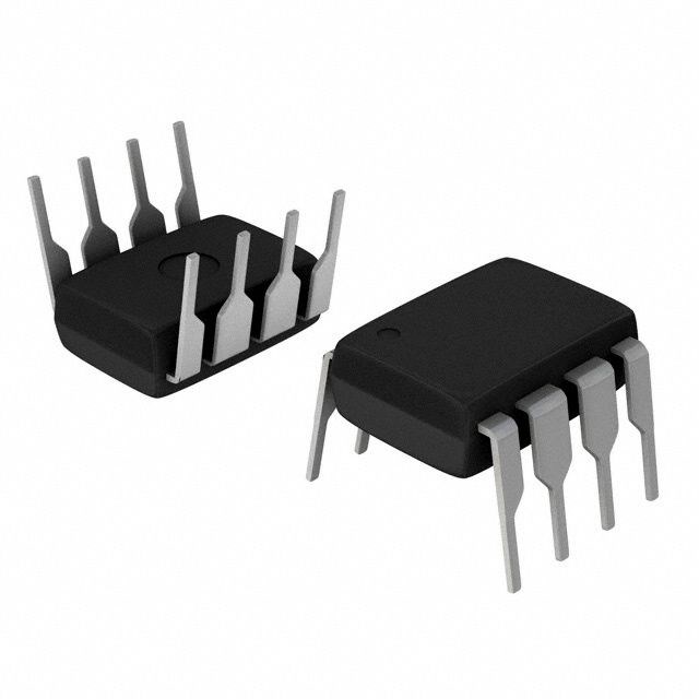
SI5345 Jitter Attenuator:Pinout, Application and Detailed Block Diagrams

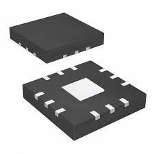
1.8V Clock Generators 64-VFQFN Exposed Pad 64 Terminals Surface Mount 1.71V~3.47V Tray


1.8V Clock Generators 64-VFQFN Exposed Pad 64 Terminals Surface Mount 1.71V~3.47V Tray
SI5345 is a jitter attenuator/clock multiplier.This blog covers its pinout,features,application and other detailed information about SI5345
SI5345 Description
SI5345 is a jitter attenuator clock multiplier, which combines fourth-generation DSPLL™ and MultiSynth™ technologies to enable any-frequency clock generation and jitter attenuation for applications requiring the highest level of jitter performance.
SI5345 Pinout

SI5345 CAD Model
Symbol

Footprint

3D Model

SI5345 Features
• Generates any combination of output frequencies from any input frequency
• Ultra-low jitter of 90 fs rms
• Input frequency range
• Differential: 8 kHz–750 MHz
• LVCMOS: 8 kHz–250 MHz
• Output frequency range
• Differential: 100 Hz to 1028 MHz
• LVCMOS: 100 Hz to 250 MHz
• Programmable jitter attenuation bandwidth: 0.1 Hz to 4 kHz
• Meets G.8262 EEC Option 1, 2 (SyncE)
• Highly configurable outputs compatible with LVDS, LVPECL,
LVCMOS, CML, and HCSL with programmable signal amplitude
• Status monitoring (LOS, OOF, LOL)
• Hitless input clock switching: automatic or manual
• Locks to gapped clock inputs
• Free-run and holdover modes
• Optional zero delay mode
• Fastlock feature for low nominal bandwidths
• Glitchless on the fly output frequency changes
• DCO mode: as low as 0.001 ppb step size
• Core voltage
• VDD: 1.8 V ±5%
• VDDA: 3.3 V ±5%
• Independent output clock supply pins
• 3.3 V, 2.5 V, or 1.8 V
• Serial interface: I2C or SPI
• In-circuit programmable with non-volatile OTP memory
• ClockBuilder Pro software simplifies device configuration
• Si5345: 4 input, 10 output, 64-QFN 9×9 mm
• Temperature range: –40 to +85 °C
• Pb-free, RoHS-6 compliant
Specifications
- TypeParameter
- Factory Lead Time6 Weeks
- Package / Case
refers to the protective housing that encases an electronic component, providing mechanical support, electrical connections, and thermal management.
64-VFQFN Exposed Pad - Mounting Type
The "Mounting Type" in electronic components refers to the method used to attach or connect a component to a circuit board or other substrate, such as through-hole, surface-mount, or panel mount.
Surface Mount - Mount
In electronic components, the term "Mount" typically refers to the method or process of physically attaching or fixing a component onto a circuit board or other electronic device. This can involve soldering, adhesive bonding, or other techniques to secure the component in place. The mounting process is crucial for ensuring proper electrical connections and mechanical stability within the electronic system. Different components may have specific mounting requirements based on their size, shape, and function, and manufacturers provide guidelines for proper mounting procedures to ensure optimal performance and reliability of the electronic device.
Surface Mount - Number of Pins64
- Published2014
- Packaging
Semiconductor package is a carrier / shell used to contain and cover one or more semiconductor components or integrated circuits. The material of the shell can be metal, plastic, glass or ceramic.
Tray - Operating Temperature
The operating temperature is the range of ambient temperature within which a power supply, or any other electrical equipment, operate in. This ranges from a minimum operating temperature, to a peak or maximum operating temperature, outside which, the power supply may fail.
-40°C~85°C - JESD-609 Code
The "JESD-609 Code" in electronic components refers to a standardized marking code that indicates the lead-free solder composition and finish of electronic components for compliance with environmental regulations.
e4 - Part Status
Parts can have many statuses as they progress through the configuration, analysis, review, and approval stages.
Not For New Designs - Moisture Sensitivity Level (MSL)
Moisture Sensitivity Level (MSL) is a standardized rating that indicates the susceptibility of electronic components, particularly semiconductors, to moisture-induced damage during storage and the soldering process, defining the allowable exposure time to ambient conditions before they require special handling or baking to prevent failures
2 (1 Year) - Number of Terminations64
- ECCN Code
An ECCN (Export Control Classification Number) is an alphanumeric code used by the U.S. Bureau of Industry and Security to identify and categorize electronic components and other dual-use items that may require an export license based on their technical characteristics and potential for military use.
EAR99 - Terminal Finish
Terminal Finish refers to the surface treatment applied to the terminals or leads of electronic components to enhance their performance and longevity. It can improve solderability, corrosion resistance, and overall reliability of the connection in electronic assemblies. Common finishes include nickel, gold, and tin, each possessing distinct properties suitable for various applications. The choice of terminal finish can significantly impact the durability and effectiveness of electronic devices.
Nickel/Palladium/Gold/Silver (Ni/Pd/Au/Ag) - Additional Feature
Any Feature, including a modified Existing Feature, that is not an Existing Feature.
ALSO REQUIRES 3.3V SUPPLY - Voltage - Supply
Voltage - Supply refers to the range of voltage levels that an electronic component or circuit is designed to operate with. It indicates the minimum and maximum supply voltage that can be applied for the device to function properly. Providing supply voltages outside this range can lead to malfunction, damage, or reduced performance. This parameter is critical for ensuring compatibility between different components in a circuit.
1.71V~3.47V - Terminal Position
In electronic components, the term "Terminal Position" refers to the physical location of the connection points on the component where external electrical connections can be made. These connection points, known as terminals, are typically used to attach wires, leads, or other components to the main body of the electronic component. The terminal position is important for ensuring proper connectivity and functionality of the component within a circuit. It is often specified in technical datasheets or component specifications to help designers and engineers understand how to properly integrate the component into their circuit designs.
QUAD - Terminal Form
Occurring at or forming the end of a series, succession, or the like; closing; concluding.
NO LEAD - Peak Reflow Temperature (Cel)
Peak Reflow Temperature (Cel) is a parameter that specifies the maximum temperature at which an electronic component can be exposed during the reflow soldering process. Reflow soldering is a common method used to attach electronic components to a circuit board. The Peak Reflow Temperature is crucial because it ensures that the component is not damaged or degraded during the soldering process. Exceeding the specified Peak Reflow Temperature can lead to issues such as component failure, reduced performance, or even permanent damage to the component. It is important for manufacturers and assemblers to adhere to the recommended Peak Reflow Temperature to ensure the reliability and functionality of the electronic components.
260 - Supply Voltage
Supply voltage refers to the electrical potential difference provided to an electronic component or circuit. It is crucial for the proper operation of devices, as it powers their functions and determines performance characteristics. The supply voltage must be within specified limits to ensure reliability and prevent damage to components. Different electronic devices have specific supply voltage requirements, which can vary widely depending on their design and intended application.
1.8V - Terminal Pitch
The center distance from one pole to the next.
0.5mm - Frequency
In electronic components, the parameter "Frequency" refers to the rate at which a signal oscillates or cycles within a given period of time. It is typically measured in Hertz (Hz) and represents how many times a signal completes a full cycle in one second. Frequency is a crucial aspect in electronic components as it determines the behavior and performance of various devices such as oscillators, filters, and communication systems. Understanding the frequency characteristics of components is essential for designing and analyzing electronic circuits to ensure proper functionality and compatibility with other components in a system.
712.5MHz - Time@Peak Reflow Temperature-Max (s)
Time@Peak Reflow Temperature-Max (s) refers to the maximum duration that an electronic component can be exposed to the peak reflow temperature during the soldering process, which is crucial for ensuring reliable solder joint formation without damaging the component.
40 - Output
In electronic components, the parameter "Output" typically refers to the signal or data that is produced by the component and sent to another part of the circuit or system. The output can be in the form of voltage, current, frequency, or any other measurable quantity depending on the specific component. The output of a component is often crucial in determining its functionality and how it interacts with other components in the circuit. Understanding the output characteristics of electronic components is essential for designing and troubleshooting electronic circuits effectively.
CML, HCSL, LVCMOS, LVDS, LVPECL - Number of Circuits1
- uPs/uCs/Peripheral ICs Type
The parameter "uPs/uCs/Peripheral ICs Type" refers to the classification of various integrated circuits used in electronic devices. It encompasses microprocessors (uPs), microcontrollers (uCs), and peripheral integrated circuits that provide additional functionalities. This classification helps in identifying the specific type of chip used for processing tasks, controlling hardware, or interfacing with other components in a system. Understanding this parameter is essential for selecting the appropriate electronic components for a given application.
CLOCK GENERATOR, PROCESSOR SPECIFIC - Input
In electronic components, "Input" refers to the signal or data that is provided to a device or system for processing or manipulation. It is the information or command that is received by the component to initiate a specific function or operation. The input can come from various sources such as sensors, other electronic devices, or user interactions. It is crucial for the proper functioning of the component as it determines how the device will respond or behave based on the input received. Understanding and managing the input parameters is essential in designing and using electronic components effectively.
LVCMOS, LVDS, LVPECL, Crystal - Ratio - Input:Output
The parameter "Ratio - Input:Output" in electronic components refers to the relationship between the input and output quantities of a device or system. It is a measure of how the input signal or energy is transformed or converted into the output signal or energy. This ratio is often expressed as a numerical value or percentage, indicating the efficiency or effectiveness of the component in converting the input to the desired output. A higher ratio typically signifies better performance or higher efficiency, while a lower ratio may indicate losses or inefficiencies in the conversion process. Understanding and optimizing the input-output ratio is crucial in designing and evaluating electronic components for various applications.
5:10 - Primary Clock/Crystal Frequency-Nom
The parameter "Primary Clock/Crystal Frequency-Nom" refers to the nominal frequency at which a clock or crystal oscillator operates in electronic components. This frequency is critical for synchronizing the timing of various processes within a circuit or system. It is typically specified in hertz and indicates the standard or average frequency that the oscillator is designed to achieve under normal operating conditions. Accurate frequency is essential for ensuring proper functioning and performance of digital circuits and communication systems.
54MHz - PLL
PLL stands for Phase-Locked Loop, which is a control system that generates an output signal whose phase is related to the phase of an input signal. It is commonly used in electronic components to synchronize, modulate, demodulate, filter, or recover a signal's frequency. A PLL typically consists of a phase detector, a loop filter, a voltage-controlled oscillator (VCO), and a feedback circuit. The PLL locks the phase of the output signal to the phase of the input signal, making it a versatile tool in various applications such as frequency synthesis, clock recovery, and frequency modulation.
Yes - Differential - Input:Output
Differential - Input:Output refers to the relationship between the input and output signals in differential amplifiers or circuits. It measures the difference in voltage between two input terminals and produces an output that is proportional to this difference. This parameter is essential for noise rejection and improving signal integrity in various applications, such as operational amplifiers and data acquisition systems. It allows circuits to effectively amplify small signals while minimizing interference and common-mode noise.
Yes/Yes - Divider/Multiplier
The parameter "Divider/Multiplier" in electronic components refers to a feature that allows the component to divide or multiply an input signal by a certain factor. This feature is commonly found in components such as operational amplifiers, voltage regulators, and signal processing circuits. In the context of operational amplifiers, the Divider/Multiplier parameter indicates the ability of the amplifier to scale the input signal by a specific factor, either dividing it or multiplying it. This can be useful for adjusting the amplitude or gain of a signal in a circuit.Overall, the Divider/Multiplier parameter provides flexibility in signal processing applications by allowing users to manipulate the input signal according to their specific requirements, whether it involves scaling down the signal for further processing or amplifying it for increased output.
Yes/No - Width9mm
- Height Seated (Max)
Height Seated (Max) is a parameter in electronic components that refers to the maximum allowable height of the component when it is properly seated or installed on a circuit board or within an enclosure. This specification is crucial for ensuring proper fit and alignment within the overall system design. Exceeding the maximum seated height can lead to mechanical interference, electrical shorts, or other issues that may impact the performance and reliability of the electronic device. Manufacturers provide this information to help designers and engineers select components that will fit within the designated space and function correctly in the intended application.
0.9mm - Length9mm
- RoHS Status
RoHS means “Restriction of Certain Hazardous Substances” in the “Hazardous Substances Directive” in electrical and electronic equipment.
RoHS Compliant
SI5345 Detailed Block Diagram

SI5345 Package


SI5345 Application
• OTN muxponders and transponders
• 10/40/100 G networking line cards
• GbE/10 GbE/100 GbE Synchronous Ethernet (ITU-T G.8262)
• Carrier Ethernet switches
• SONET/SDH line cards
• Broadcast video
• Test and measurement
• ITU-T G.8262 (SyncE) compliant
SI5345 Manufacturer
Silicon Labs (NASDAQ: SLAB) is a leading provider of silicon, software and system solutions for the Internet of Things, Internet infrastructure, industrial control, consumer and automotive markets. Resolving the electronics industry's toughest problems, providing customers with significant advantages in performance, energy savings, connectivity, and design simplicity. Backed by world-class engineering teams with unsurpassed software and mixed-signal design expertise, Silicon Labs empowers developers with the tools and technologies they need to advance quickly and easily from initial idea to final product.
Datasheet PDF
- Datasheets :
- PCN Other :
- PCN Design/Specification :
Popularity by Region
What is the Reference Manual for the SI5345?
Any-frequency, Any-output Jitter-Attenuators/Clock Multipliers Si5345, Si5344, Si5342 Family Reference Manual This Family Reference Manual is intended to provide system, PCB design, signal integrity, and software engineers the necessary technical information to successfully use the Si5345/44/42 devices in end applications.
Can A Zynq based system be initialized with SI5345?
For Zynq based system Si5345 can be initialized during FSBL execution. For FPGA based modules init can be done by the application MicroBlaze. Examples are included in the reference designs. Procedure with FSBL or MicroBlaze c code:
Is it possible to program a SI5345?
Programming the Si5345 is easy with Silicon Labs’ ClockBuilder Pro™software. Factory preprogrammed devices are also available.
Is the SI5345 loop filter programmable?
The loop filter is fully integrated on-chip, eliminating the risk of noise coupling associated with discrete solutions. Furthermore, the jitter attenuation bandwidth is digitally programmable, providing jitte perform- ance optimization at the application level. Programming the Si5345 is easy with Silicon Labs’ ClockBuilder Pro™software.
 XC7Z020-1CLG400C Features Explained for 2025 Applications
27 March 20251423
 TL082CP Operational Amplifier: Pinout, Datasheet, and Typical Applications
20 July 202110356
 PMV65XP Trench MOSFET: Datasheet, Alternatives, Pinout, SOT-23
12 February 20223477
 2P4M SCR: Datasheet, Pin and Circuit
09 November 20219378
 LM193 Dual Voltage Comparator: Pinout, Equivalent and Datasheet
06 November 20212030
 TDA7377 Class AB Car Radio Amplifier: Pinout, Datasheet pdf and Circuit
07 December 202124476
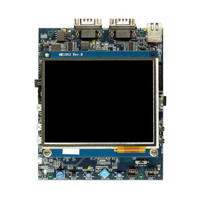 STM32H743I-EVAL: Specifications, Features and Applications
23 July 2025424
 HMC344LC3TR-R5 RF Switch: Pinout, Feature, Datasheet
14 August 2024428
 What is a USB Data Cable?
27 August 202114283
 Electronic Components Distributor Utmel to Showcase at 2024 IPC APEX EXPO
10 April 20245466
 How to Properly Install TVS Diodes in Your PCB Design
11 July 20253788
 A New Way of Thinking About the "Trolley Problem" of Artificial Intelligence
27 May 20221618
 Detailed Analysis of Analog IC
22 November 20213422
 Msemitek Authorized Distributor | UTMEL Electronics
21 November 20233515
 Next-Generation Flexible Display Technology - QLED
11 October 20214791
 Four Proximity Sensors PK, Who can Win?
08 April 20222180
Silicon Labs
In Stock: 66
United States
China
Canada
Japan
Russia
Germany
United Kingdom
Singapore
Italy
Hong Kong(China)
Taiwan(China)
France
Korea
Mexico
Netherlands
Malaysia
Austria
Spain
Switzerland
Poland
Thailand
Vietnam
India
United Arab Emirates
Afghanistan
Åland Islands
Albania
Algeria
American Samoa
Andorra
Angola
Anguilla
Antigua & Barbuda
Argentina
Armenia
Aruba
Australia
Azerbaijan
Bahamas
Bahrain
Bangladesh
Barbados
Belarus
Belgium
Belize
Benin
Bermuda
Bhutan
Bolivia
Bonaire, Sint Eustatius and Saba
Bosnia & Herzegovina
Botswana
Brazil
British Indian Ocean Territory
British Virgin Islands
Brunei
Bulgaria
Burkina Faso
Burundi
Cabo Verde
Cambodia
Cameroon
Cayman Islands
Central African Republic
Chad
Chile
Christmas Island
Cocos (Keeling) Islands
Colombia
Comoros
Congo
Congo (DRC)
Cook Islands
Costa Rica
Côte d’Ivoire
Croatia
Cuba
Curaçao
Cyprus
Czechia
Denmark
Djibouti
Dominica
Dominican Republic
Ecuador
Egypt
El Salvador
Equatorial Guinea
Eritrea
Estonia
Eswatini
Ethiopia
Falkland Islands
Faroe Islands
Fiji
Finland
French Guiana
French Polynesia
Gabon
Gambia
Georgia
Ghana
Gibraltar
Greece
Greenland
Grenada
Guadeloupe
Guam
Guatemala
Guernsey
Guinea
Guinea-Bissau
Guyana
Haiti
Honduras
Hungary
Iceland
Indonesia
Iran
Iraq
Ireland
Isle of Man
Israel
Jamaica
Jersey
Jordan
Kazakhstan
Kenya
Kiribati
Kosovo
Kuwait
Kyrgyzstan
Laos
Latvia
Lebanon
Lesotho
Liberia
Libya
Liechtenstein
Lithuania
Luxembourg
Macao(China)
Madagascar
Malawi
Maldives
Mali
Malta
Marshall Islands
Martinique
Mauritania
Mauritius
Mayotte
Micronesia
Moldova
Monaco
Mongolia
Montenegro
Montserrat
Morocco
Mozambique
Myanmar
Namibia
Nauru
Nepal
New Caledonia
New Zealand
Nicaragua
Niger
Nigeria
Niue
Norfolk Island
North Korea
North Macedonia
Northern Mariana Islands
Norway
Oman
Pakistan
Palau
Palestinian Authority
Panama
Papua New Guinea
Paraguay
Peru
Philippines
Pitcairn Islands
Portugal
Puerto Rico
Qatar
Réunion
Romania
Rwanda
Samoa
San Marino
São Tomé & Príncipe
Saudi Arabia
Senegal
Serbia
Seychelles
Sierra Leone
Sint Maarten
Slovakia
Slovenia
Solomon Islands
Somalia
South Africa
South Sudan
Sri Lanka
St Helena, Ascension, Tristan da Cunha
St. Barthélemy
St. Kitts & Nevis
St. Lucia
St. Martin
St. Pierre & Miquelon
St. Vincent & Grenadines
Sudan
Suriname
Svalbard & Jan Mayen
Sweden
Syria
Tajikistan
Tanzania
Timor-Leste
Togo
Tokelau
Tonga
Trinidad & Tobago
Tunisia
Turkey
Turkmenistan
Turks & Caicos Islands
Tuvalu
U.S. Outlying Islands
U.S. Virgin Islands
Uganda
Ukraine
Uruguay
Uzbekistan
Vanuatu
Vatican City
Venezuela
Wallis & Futuna
Yemen
Zambia
Zimbabwe
![SI5310-BM]() SI5310-BM
SI5310-BMSilicon Labs
![SI5342B-D-GM]() SI5342B-D-GM
SI5342B-D-GMSilicon Labs
![SI51214-A1FAGMR]() SI51214-A1FAGMR
SI51214-A1FAGMRSilicon Labs
![SI5351A-B-GTR]() SI5351A-B-GTR
SI5351A-B-GTRSilicon Labs
![SI5351A-B-GM]() SI5351A-B-GM
SI5351A-B-GMSilicon Labs
![SI5326B-C-GM]() SI5326B-C-GM
SI5326B-C-GMSilicon Labs
![SI5351B-B-GM]() SI5351B-B-GM
SI5351B-B-GMSilicon Labs
![SI5351A-B-GT]() SI5351A-B-GT
SI5351A-B-GTSilicon Labs
![SI5351C-B-GMR]() SI5351C-B-GMR
SI5351C-B-GMRSilicon Labs
![SI5326B-C-GMR]() SI5326B-C-GMR
SI5326B-C-GMRSilicon Labs


