THS7314 Video Amplifiers:Pinout, Datasheet and Application
8 Terminations 2.85V~5.5V 8 Pin THS7314 Video Amps Modules 3 Functions Min -40°C Max 85°C
Unit Price: $0.175968
Ext Price: $0.18


8 Terminations 2.85V~5.5V 8 Pin THS7314 Video Amps Modules 3 Functions Min -40°C Max 85°C
The THS7314 is a 3-Channel SDTV Video Amplifier. This article mainly introduce its pinout, datasheet, application and other detailed information about Texas Instruments THS7314.

Nintendo 64 RGB - Comparison Composite, THS7314, RGB Officiel (SUBS AVAILABLE)
THS7314 Description
Fabricated using the Silicon-Germanium (SiGe) BiCom-III process, the THS7314 is a low power single-supply 3-V to 5-V 3-channel integrated video buffer. It incorporates a 5th-order Butterworth filter which is useful as a DAC reconstruction filter or an ADC anti-aliasing filter. The 8.5-MHz filter is a perfect choice for SDTV video which includes Composite (CVBS), S-Video, Y'U'V', G'B'R' (R'G'B'), and Y'P'BP'R 480i/576i.
As part of the THS7314 flexibility, the input can be configured for ac or dc coupled inputs. The 285-mV output level shift to allow for a full sync dynamic range at the output with 0-V input. The AC coupled modes include a transparent sync-tip clamp option for CVBS, Y', and G'B'R' signals with sync. AC-coupled biasing for C'/P'B/P'R channels is achieved by adding an external resistor to Vs+.
The THS7314 is the perfect choice for all output buffer applications. Its rail-to-rail output stage with 6-dB gain allows for both ac and dc line driving. The ability to drive 2-lines, or 75-Ω loads, allows for maximum flexibility as a video line driver. The 16-mA total quiescent current at 3.3-V makes it an excellent choice for USB powered, portable, or other power sensitive video applications.
The THS7314 is available in a small SOIC-8 package that is RoHS compliant.
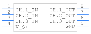
THS7314 Pinout
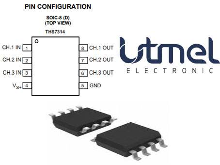

THS7314 CAD Model
Symbol
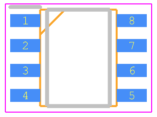
Footprint
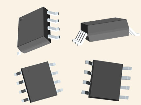
3D Model
THS7314 Features
• 3 SDTV Video Amplifiers for CVBS, S-Video, Y'P'BP'R 480i/576i, Y'U'V', or G'B'R' (R'G'B')
• Integrated Low-Pass Filters
– 5 Order 8.5-MHz (–3dB) Butterworth buffer.
– –1dB Passband Bandwidth at 7-MHz
– 47dB Attenuation at 27-MHz
• Versatile Input Biasing
– DC-Coupled With 285-mV Output Shift
– AC-Coupled with Sync-Tip Clamp
– Allows AC-Coupled With DC-Biasing
• Built-in 6dB Gain (2V/V)
• 3-V to 5-V Single Supply Operation
• Rail-to-Rail Output:
– Output Swings Within 100-mV From the Rails Allowing AC or DC Output Coupling
– Able to Drive up to 2 Video Lines – 75 Ω
• Low 16-mA at 3.3-V Total Quiscent Current
• Low Differential Gain/Phase of 0.1% / 0.1°
• SOIC-8 Package
Specifications
- TypeParameter
- Lifecycle Status
Lifecycle Status refers to the current stage of an electronic component in its product life cycle, indicating whether it is active, obsolete, or transitioning between these states. An active status means the component is in production and available for purchase. An obsolete status indicates that the component is no longer being manufactured or supported, and manufacturers typically provide a limited time frame for support. Understanding the lifecycle status is crucial for design engineers to ensure continuity and reliability in their projects.
ACTIVE (Last Updated: 5 days ago) - Factory Lead Time6 Weeks
- Mount
In electronic components, the term "Mount" typically refers to the method or process of physically attaching or fixing a component onto a circuit board or other electronic device. This can involve soldering, adhesive bonding, or other techniques to secure the component in place. The mounting process is crucial for ensuring proper electrical connections and mechanical stability within the electronic system. Different components may have specific mounting requirements based on their size, shape, and function, and manufacturers provide guidelines for proper mounting procedures to ensure optimal performance and reliability of the electronic device.
Surface Mount - Mounting Type
The "Mounting Type" in electronic components refers to the method used to attach or connect a component to a circuit board or other substrate, such as through-hole, surface-mount, or panel mount.
Surface Mount - Package / Case
refers to the protective housing that encases an electronic component, providing mechanical support, electrical connections, and thermal management.
8-SOIC (0.154, 3.90mm Width) - Number of Pins8
- Weight75.891673mg
- Packaging
Semiconductor package is a carrier / shell used to contain and cover one or more semiconductor components or integrated circuits. The material of the shell can be metal, plastic, glass or ceramic.
Tube - JESD-609 Code
The "JESD-609 Code" in electronic components refers to a standardized marking code that indicates the lead-free solder composition and finish of electronic components for compliance with environmental regulations.
e4 - Pbfree Code
The "Pbfree Code" parameter in electronic components refers to the code or marking used to indicate that the component is lead-free. Lead (Pb) is a toxic substance that has been widely used in electronic components for many years, but due to environmental concerns, there has been a shift towards lead-free alternatives. The Pbfree Code helps manufacturers and users easily identify components that do not contain lead, ensuring compliance with regulations and promoting environmentally friendly practices. It is important to pay attention to the Pbfree Code when selecting electronic components to ensure they meet the necessary requirements for lead-free applications.
yes - Part Status
Parts can have many statuses as they progress through the configuration, analysis, review, and approval stages.
Active - Moisture Sensitivity Level (MSL)
Moisture Sensitivity Level (MSL) is a standardized rating that indicates the susceptibility of electronic components, particularly semiconductors, to moisture-induced damage during storage and the soldering process, defining the allowable exposure time to ambient conditions before they require special handling or baking to prevent failures
2 (1 Year) - Number of Terminations8
- ECCN Code
An ECCN (Export Control Classification Number) is an alphanumeric code used by the U.S. Bureau of Industry and Security to identify and categorize electronic components and other dual-use items that may require an export license based on their technical characteristics and potential for military use.
EAR99 - Terminal Finish
Terminal Finish refers to the surface treatment applied to the terminals or leads of electronic components to enhance their performance and longevity. It can improve solderability, corrosion resistance, and overall reliability of the connection in electronic assemblies. Common finishes include nickel, gold, and tin, each possessing distinct properties suitable for various applications. The choice of terminal finish can significantly impact the durability and effectiveness of electronic devices.
Nickel/Palladium/Gold (Ni/Pd/Au) - Max Operating Temperature
The Maximum Operating Temperature is the maximum body temperature at which the thermistor is designed to operate for extended periods of time with acceptable stability of its electrical characteristics.
85°C - Min Operating Temperature
The "Min Operating Temperature" parameter in electronic components refers to the lowest temperature at which the component is designed to operate effectively and reliably. This parameter is crucial for ensuring the proper functioning and longevity of the component, as operating below this temperature may lead to performance issues or even damage. Manufacturers specify the minimum operating temperature to provide guidance to users on the environmental conditions in which the component can safely operate. It is important to adhere to this parameter to prevent malfunctions and ensure the overall reliability of the electronic system.
-40°C - Applications
The parameter "Applications" in electronic components refers to the specific uses or functions for which a component is designed. It encompasses various fields such as consumer electronics, industrial automation, telecommunications, automotive, and medical devices. Understanding the applications helps in selecting the right components for a particular design based on performance, reliability, and compatibility requirements. This parameter also guides manufacturers in targeting their products to relevant markets and customer needs.
Buffer - Terminal Position
In electronic components, the term "Terminal Position" refers to the physical location of the connection points on the component where external electrical connections can be made. These connection points, known as terminals, are typically used to attach wires, leads, or other components to the main body of the electronic component. The terminal position is important for ensuring proper connectivity and functionality of the component within a circuit. It is often specified in technical datasheets or component specifications to help designers and engineers understand how to properly integrate the component into their circuit designs.
DUAL - Terminal Form
Occurring at or forming the end of a series, succession, or the like; closing; concluding.
GULL WING - Peak Reflow Temperature (Cel)
Peak Reflow Temperature (Cel) is a parameter that specifies the maximum temperature at which an electronic component can be exposed during the reflow soldering process. Reflow soldering is a common method used to attach electronic components to a circuit board. The Peak Reflow Temperature is crucial because it ensures that the component is not damaged or degraded during the soldering process. Exceeding the specified Peak Reflow Temperature can lead to issues such as component failure, reduced performance, or even permanent damage to the component. It is important for manufacturers and assemblers to adhere to the recommended Peak Reflow Temperature to ensure the reliability and functionality of the electronic components.
260 - Number of Functions3
- Terminal Pitch
The center distance from one pole to the next.
1.27mm - Base Part Number
The "Base Part Number" (BPN) in electronic components serves a similar purpose to the "Base Product Number." It refers to the primary identifier for a component that captures the essential characteristics shared by a group of similar components. The BPN provides a fundamental way to reference a family or series of components without specifying all the variations and specific details.
THS7314 - Pin Count
a count of all of the component leads (or pins)
8 - Output Type
The "Output Type" parameter in electronic components refers to the type of signal or data that is produced by the component as an output. This parameter specifies the nature of the output signal, such as analog or digital, and can also include details about the voltage levels, current levels, frequency, and other characteristics of the output signal. Understanding the output type of a component is crucial for ensuring compatibility with other components in a circuit or system, as well as for determining how the output signal can be utilized or processed further. In summary, the output type parameter provides essential information about the nature of the signal that is generated by the electronic component as its output.
Rail-to-Rail - Temperature Grade
Temperature grades represent a tire's resistance to heat and its ability to dissipate heat when tested under controlled laboratory test conditions.
INDUSTRIAL - Number of Channels3
- Operating Supply Current
Operating Supply Current, also known as supply current or quiescent current, is a crucial parameter in electronic components that indicates the amount of current required for the device to operate under normal conditions. It represents the current drawn by the component from the power supply while it is functioning. This parameter is important for determining the power consumption of the component and is typically specified in datasheets to help designers calculate the overall power requirements of their circuits. Understanding the operating supply current is essential for ensuring proper functionality and efficiency of electronic systems.
16mA - Nominal Supply Current
Nominal current is the same as the rated current. It is the current drawn by the motor while delivering rated mechanical output at its shaft.
16mA - Output Current
The rated output current is the maximum load current that a power supply can provide at a specified ambient temperature. A power supply can never provide more current that it's rated output current unless there is a fault, such as short circuit at the load.
70mA - Voltage - Supply, Single/Dual (±)
The parameter "Voltage - Supply, Single/Dual (±)" in electronic components refers to the power supply voltage required for the proper operation of the component. This parameter indicates whether the component requires a single power supply voltage (e.g., 5V) or a dual power supply voltage (e.g., ±15V). For components that require a single power supply voltage, only one voltage level is needed for operation. On the other hand, components that require a dual power supply voltage need both positive and negative voltage levels to function correctly.Understanding the voltage supply requirements of electronic components is crucial for designing and integrating them into circuits to ensure proper functionality and prevent damage due to incorrect voltage levels.
2.85V~5.5V - Output Current per Channel
Output Current per Channel is a specification commonly found in electronic components such as amplifiers, audio interfaces, and power supplies. It refers to the maximum amount of electrical current that can be delivered by each individual output channel of the component. This parameter is important because it determines the capacity of the component to drive connected devices or loads. A higher output current per channel means the component can deliver more power to connected devices, while a lower output current may limit the performance or functionality of the component in certain applications. It is crucial to consider the output current per channel when selecting electronic components to ensure they can meet the power requirements of the intended system or setup.
70mA - Supply Type
Supply Type in electronic components refers to the classification of power sources used to operate the component. It indicates whether the component requires DC or AC power, and if DC, specifies the voltage levels such as low, medium, or high. Different supply types can affect the performance, compatibility, and application of the component in electronic circuits. Understanding the supply type is crucial for proper component selection and integration into electronic designs.
Single - Bandwidth
In electronic components, "Bandwidth" refers to the range of frequencies over which the component can effectively operate or pass signals without significant loss or distortion. It is a crucial parameter for devices like amplifiers, filters, and communication systems. The bandwidth is typically defined as the difference between the upper and lower frequencies at which the component's performance meets specified criteria, such as a certain level of signal attenuation or distortion. A wider bandwidth indicates that the component can handle a broader range of frequencies, making it more versatile for various applications. Understanding the bandwidth of electronic components is essential for designing and optimizing circuits to ensure proper signal transmission and reception within the desired frequency range.
8500 kHz - Gain
In electronic components, "Gain" refers to the ratio of the output signal amplitude to the input signal amplitude. It is a measure of the amplification provided by the component, such as a transistor or operational amplifier. Gain is typically expressed in decibels (dB) or as a numerical value, indicating how much the signal is amplified by the component.A higher gain value indicates a greater amplification of the input signal, while a lower gain value indicates less amplification. Gain is an important parameter in designing and analyzing electronic circuits, as it determines the overall performance and functionality of the system. Different components have different gain characteristics, and understanding the gain of a component is crucial for achieving the desired signal processing or amplification in electronic systems.
6 dB - Consumer IC Type
Consumer IC Type refers to the specific type of integrated circuit (IC) that is designed for use in consumer electronic devices. These ICs are typically optimized for applications in products such as smartphones, tablets, televisions, and other consumer electronics. They are often characterized by features such as low power consumption, small form factor, and high performance to meet the demands of modern consumer devices. Consumer IC types may include microcontrollers, audio amplifiers, display drivers, and other specialized chips tailored for consumer electronics applications. Manufacturers develop and market these ICs to meet the unique requirements of the consumer electronics industry, providing solutions for a wide range of functions and applications in modern devices.
AUDIO AMPLIFIER - Height1.75mm
- Length4.9mm
- Width3.91mm
- Thickness
Thickness in electronic components refers to the measurement of how thick a particular material or layer is within the component structure. It can pertain to various aspects, such as the thickness of a substrate, a dielectric layer, or conductive traces. This parameter is crucial as it impacts the electrical, mechanical, and thermal properties of the component, influencing its performance and reliability in electronic circuits.
1.58mm - REACH SVHC
The parameter "REACH SVHC" in electronic components refers to the compliance with the Registration, Evaluation, Authorization, and Restriction of Chemicals (REACH) regulation regarding Substances of Very High Concern (SVHC). SVHCs are substances that may have serious effects on human health or the environment, and their use is regulated under REACH to ensure their safe handling and minimize their impact.Manufacturers of electronic components need to declare if their products contain any SVHCs above a certain threshold concentration and provide information on the safe use of these substances. This information allows customers to make informed decisions about the potential risks associated with using the components and take appropriate measures to mitigate any hazards.Ensuring compliance with REACH SVHC requirements is essential for electronics manufacturers to meet regulatory standards, protect human health and the environment, and maintain transparency in their supply chain. It also demonstrates a commitment to sustainability and responsible manufacturing practices in the electronics industry.
No SVHC - Radiation Hardening
Radiation hardening is the process of making electronic components and circuits resistant to damage or malfunction caused by high levels of ionizing radiation, especially for environments in outer space (especially beyond the low Earth orbit), around nuclear reactors and particle accelerators, or during nuclear accidents or nuclear warfare.
No - RoHS Status
RoHS means “Restriction of Certain Hazardous Substances” in the “Hazardous Substances Directive” in electrical and electronic equipment.
ROHS3 Compliant - Lead Free
Lead Free is a term used to describe electronic components that do not contain lead as part of their composition. Lead is a toxic material that can have harmful effects on human health and the environment, so the electronics industry has been moving towards lead-free components to reduce these risks. Lead-free components are typically made using alternative materials such as silver, copper, and tin. Manufacturers must comply with regulations such as the Restriction of Hazardous Substances (RoHS) directive to ensure that their products are lead-free and environmentally friendly.
Lead Free
THS7314 Applications
• Set Top Box Output Video Buffering
• PVR/DVDR Output Buffering
• USB/Portable Low Power Video Buffering
THS7314 Schematic
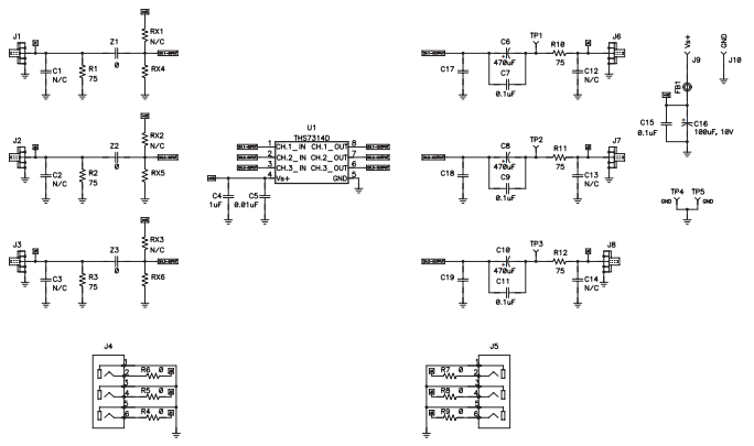
THS7314 Circuit
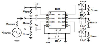
.AC Coupled Input and Output Test Circuit
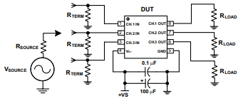
.DC Coupled Input and Output Test Circuit
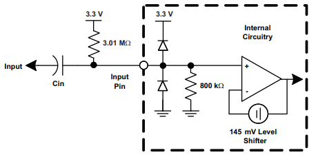
AC-Bias Input Mode Circuit Configuration
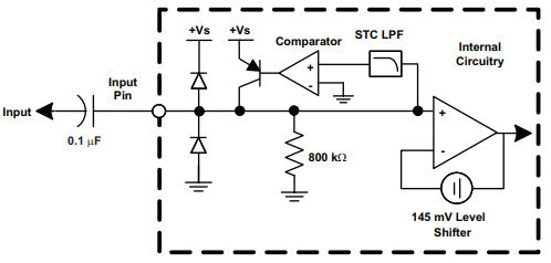
Equivalent AC Sync Tip Clamp Input Circuit
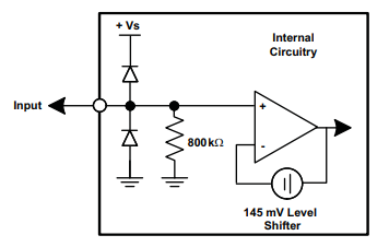
Equivalent DC Input Mode Circuit
THS7314 Functional Diagram
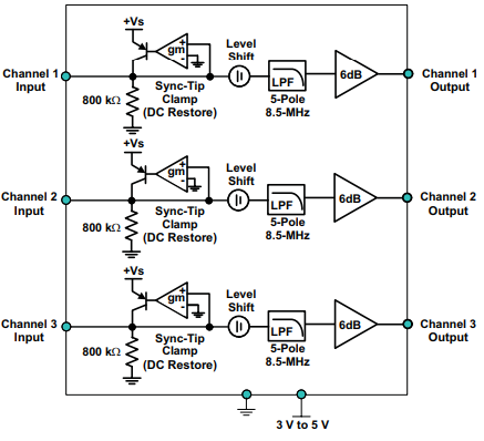
THS7314 Manufacturer
As a global semiconductor company operating in 35 countries, Texas Instruments (TI) is first and foremost a reflection of its people. From the TIer who unveiled the first working integrated circuit in 1958 to the more than 30,000 TIers around the world today who design, manufacture and sell analog and embedded processing chips, we are problem-solvers collaborating to change the world through technology.
Trend Analysis
Datasheet PDF
- Datasheets :
![1N5407 Diode: Datasheet, Equivalent, 1N5407 vs.1N5408 [Video]](https://res.utmel.com/Images/Article/0db19f75-5fe5-4bd7-a599-a348ffbfb061.jpg) 1N5407 Diode: Datasheet, Equivalent, 1N5407 vs.1N5408 [Video]
1N5407 Diode: Datasheet, Equivalent, 1N5407 vs.1N5408 [Video]22 December 20212710
![LMR® -400 Coaxial Cables (RF) 50Ohms[Video]:Datasheet, Features, and Applications](https://res.utmel.com/Images/Article/fee4ddfa-7969-484f-ac95-2f6daa997670.png) LMR® -400 Coaxial Cables (RF) 50Ohms[Video]:Datasheet, Features, and Applications
LMR® -400 Coaxial Cables (RF) 50Ohms[Video]:Datasheet, Features, and Applications12 June 20243877
 TPS62745DSSR: Step-Down, Datasheet, Ultra-Low Power
28 February 20223655
 LME49720 Audio Operational Amplifier: Circuit, Price and Alternatives
29 June 20214211
 Understanding MSP430G2x53 and MSP430G2x13 Mixed-Signal Microcontrollers
29 February 2024121
 STM32F410RBT7 Microcontroller: Pinout, Datasheet, and Circuit
30 June 20211892
 W25Q64JVSSIQ: Overview, Features, and Datasheet
25 October 20232612
 TL431 Shunt Regulator: Where & How to Use TL431?
02 December 202110327
 DoD Allocates $238 Million for Semiconductor Centers under CHIPS and Science Act
23 September 20231002
 What is a Memory Controller?
12 August 202031838
 Essential Tips for Picking the Best Gas Sensor
15 July 20251492
 Types and Application of Position Sensors
31 October 20256013
 Solid State Relay Basics: Working, Features and Structure
17 September 20207422
 Structure and Imaging Principle of Smartphone Camera
26 November 202119005
 What is Power Factor Correction (PFC)?
10 December 20213499
 An Overview of Digital Signal Processor
31 October 20257668
Texas Instruments
In Stock: 1
Minimum: 1 Multiples: 1
Qty
Unit Price
Ext Price
1
$0.175968
$0.18
10
$0.166007
$1.66
100
$0.156611
$15.66
500
$0.147746
$73.87
1000
$0.139383
$139.38
Not the price you want? Send RFQ Now and we'll contact you ASAP.
Inquire for More Quantity


