
AD9850 DDS Synthesizer: Pinout, Schematic and Datasheet

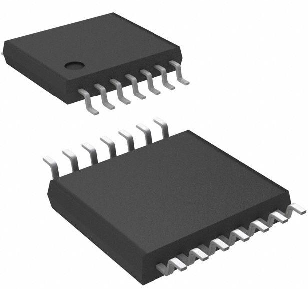
28 Termination 0.65mm Lead, Tin Direct Digital Synthesis AD9850 28 Pin 125MHz 5V 28-SSOP (0.209, 5.30mm Width)
Unit Price: $14.205996
Ext Price: $14.21


28 Termination 0.65mm Lead, Tin Direct Digital Synthesis AD9850 28 Pin 125MHz 5V 28-SSOP (0.209, 5.30mm Width)
AD9850 is a CMOS, 125 MHz complete DDS synthesizer. This article mainly introduce its pinout,schematic, datasheet and other detaialed information about Analog Devices AD9850.

DIY No Frills AD9850/Arduino Antenna Analyzer
AD9850 Description
The AD9850 is a highly integrated device, using advanced DDS technology plus internal high-speed, high-speed performance D/A converter and comparator form a complete, digital programmable frequency synthesizer and Clock generator function.
When referring to an accurate as a clock source, AD9850 generates an analog output sine wave with pure spectrum and programmable frequency/phase.
The sine wave can be used directly as a frequency source, or convert to a square wave for use in agile clock generator applications.
AD9850's innovative high-speed DDS core provides A 32-bit frequency tuning word produces an output the 125 MHz reference clock has a tuning resolution of 0.0291 Hz enter.
The circuit architecture of AD9850 allows to generate Up to one-half of the output frequency of the reference clock frequency (or 62.5 MHz), and the output frequency can be digitally changed (asynchronous) at a rate of up to 23 million new Frequency per second.
The device also provides five Digitally controlled phase modulation, so that the phase Move its output in increments of 180°, 90°, 45°, 22.5°, 11.25° and any combination thereof.
AD9850 also contains A high-speed comparator that can be configured to accept The (external) filtered output of the DAC to generate low jitter Square wave output.
This helps to use the device as Flexible clock generator function. Frequency tuning, control and phase modulation words are Load to AD9850 via parallel byte or serial load format.
The parallel loading format consists of five iterative loadings 8-bit control word (byte). The first byte control stage Modulation, power-down enable and load format; byte 2 to 5 Contains 32-bit frequency tuning word.
Serial loading is This is done through a 40-bit serial data stream on a single pin. This AD9850 complete DDS uses advanced CMOS technology
Provide this groundbreaking level of functionality and performance the power consumption is only 155 mW (3.3 V power supply). AD9850 uses a space-saving 28-pin SSOP, Surface mount package. It is designated in Extended industrial temperature range from –40°C to +85°C.
AD9850 Pinout
Pin Number: 28

Pin Function

AD9850 CAD Model
Symbol

Footprint

AD9850 Features
★25 MHz clock frequency
★On-chip high-performance DAC and high-speed comparators
★DAC SFDR> 50 dB @ 40 MHz AOUT
★32-bit frequency tuning word
★Simplified control interface: parallel byte or serial
★Loading format
★Phase modulation capability
★3.3V or 5V single power supply operation
★Low power consumption: 380 mW @ 125 MHz (5 V)
★Low power consumption: 155 mW @ 110 MHz (3.3 V)
★Power down function
★Ultra-small 28-pin SSOP package
Specifications
- TypeParameter
- Lifecycle Status
Lifecycle Status refers to the current stage of an electronic component in its product life cycle, indicating whether it is active, obsolete, or transitioning between these states. An active status means the component is in production and available for purchase. An obsolete status indicates that the component is no longer being manufactured or supported, and manufacturers typically provide a limited time frame for support. Understanding the lifecycle status is crucial for design engineers to ensure continuity and reliability in their projects.
PRODUCTION (Last Updated: 3 weeks ago) - Factory Lead Time8 Weeks
- Contact Plating
Contact plating (finish) provides corrosion protection for base metals and optimizes the mechanical and electrical properties of the contact interfaces.
Lead, Tin - Mount
In electronic components, the term "Mount" typically refers to the method or process of physically attaching or fixing a component onto a circuit board or other electronic device. This can involve soldering, adhesive bonding, or other techniques to secure the component in place. The mounting process is crucial for ensuring proper electrical connections and mechanical stability within the electronic system. Different components may have specific mounting requirements based on their size, shape, and function, and manufacturers provide guidelines for proper mounting procedures to ensure optimal performance and reliability of the electronic device.
Surface Mount - Mounting Type
The "Mounting Type" in electronic components refers to the method used to attach or connect a component to a circuit board or other substrate, such as through-hole, surface-mount, or panel mount.
Surface Mount - Package / Case
refers to the protective housing that encases an electronic component, providing mechanical support, electrical connections, and thermal management.
28-SSOP (0.209, 5.30mm Width) - Number of Pins28
- Operating Temperature
The operating temperature is the range of ambient temperature within which a power supply, or any other electrical equipment, operate in. This ranges from a minimum operating temperature, to a peak or maximum operating temperature, outside which, the power supply may fail.
-40°C~85°C - Packaging
Semiconductor package is a carrier / shell used to contain and cover one or more semiconductor components or integrated circuits. The material of the shell can be metal, plastic, glass or ceramic.
Tube - JESD-609 Code
The "JESD-609 Code" in electronic components refers to a standardized marking code that indicates the lead-free solder composition and finish of electronic components for compliance with environmental regulations.
e0 - Pbfree Code
The "Pbfree Code" parameter in electronic components refers to the code or marking used to indicate that the component is lead-free. Lead (Pb) is a toxic substance that has been widely used in electronic components for many years, but due to environmental concerns, there has been a shift towards lead-free alternatives. The Pbfree Code helps manufacturers and users easily identify components that do not contain lead, ensuring compliance with regulations and promoting environmentally friendly practices. It is important to pay attention to the Pbfree Code when selecting electronic components to ensure they meet the necessary requirements for lead-free applications.
no - Part Status
Parts can have many statuses as they progress through the configuration, analysis, review, and approval stages.
Active - Moisture Sensitivity Level (MSL)
Moisture Sensitivity Level (MSL) is a standardized rating that indicates the susceptibility of electronic components, particularly semiconductors, to moisture-induced damage during storage and the soldering process, defining the allowable exposure time to ambient conditions before they require special handling or baking to prevent failures
1 (Unlimited) - Number of Terminations28
- ECCN Code
An ECCN (Export Control Classification Number) is an alphanumeric code used by the U.S. Bureau of Industry and Security to identify and categorize electronic components and other dual-use items that may require an export license based on their technical characteristics and potential for military use.
EAR99 - Max Power Dissipation
The maximum power that the MOSFET can dissipate continuously under the specified thermal conditions.
480mW - Voltage - Supply
Voltage - Supply refers to the range of voltage levels that an electronic component or circuit is designed to operate with. It indicates the minimum and maximum supply voltage that can be applied for the device to function properly. Providing supply voltages outside this range can lead to malfunction, damage, or reduced performance. This parameter is critical for ensuring compatibility between different components in a circuit.
3.3V 5V - Terminal Position
In electronic components, the term "Terminal Position" refers to the physical location of the connection points on the component where external electrical connections can be made. These connection points, known as terminals, are typically used to attach wires, leads, or other components to the main body of the electronic component. The terminal position is important for ensuring proper connectivity and functionality of the component within a circuit. It is often specified in technical datasheets or component specifications to help designers and engineers understand how to properly integrate the component into their circuit designs.
DUAL - Terminal Form
Occurring at or forming the end of a series, succession, or the like; closing; concluding.
GULL WING - Peak Reflow Temperature (Cel)
Peak Reflow Temperature (Cel) is a parameter that specifies the maximum temperature at which an electronic component can be exposed during the reflow soldering process. Reflow soldering is a common method used to attach electronic components to a circuit board. The Peak Reflow Temperature is crucial because it ensures that the component is not damaged or degraded during the soldering process. Exceeding the specified Peak Reflow Temperature can lead to issues such as component failure, reduced performance, or even permanent damage to the component. It is important for manufacturers and assemblers to adhere to the recommended Peak Reflow Temperature to ensure the reliability and functionality of the electronic components.
240 - Supply Voltage
Supply voltage refers to the electrical potential difference provided to an electronic component or circuit. It is crucial for the proper operation of devices, as it powers their functions and determines performance characteristics. The supply voltage must be within specified limits to ensure reliability and prevent damage to components. Different electronic devices have specific supply voltage requirements, which can vary widely depending on their design and intended application.
5V - Terminal Pitch
The center distance from one pole to the next.
0.65mm - Reach Compliance Code
Reach Compliance Code refers to a designation indicating that electronic components meet the requirements set by the Registration, Evaluation, Authorization, and Restriction of Chemicals (REACH) regulation in the European Union. It signifies that the manufacturer has assessed and managed the chemical substances within the components to ensure safety and environmental protection. This code is vital for compliance with regulations aimed at minimizing risks associated with hazardous substances in electronic products.
not_compliant - Frequency
In electronic components, the parameter "Frequency" refers to the rate at which a signal oscillates or cycles within a given period of time. It is typically measured in Hertz (Hz) and represents how many times a signal completes a full cycle in one second. Frequency is a crucial aspect in electronic components as it determines the behavior and performance of various devices such as oscillators, filters, and communication systems. Understanding the frequency characteristics of components is essential for designing and analyzing electronic circuits to ensure proper functionality and compatibility with other components in a system.
125MHz - Time@Peak Reflow Temperature-Max (s)
Time@Peak Reflow Temperature-Max (s) refers to the maximum duration that an electronic component can be exposed to the peak reflow temperature during the soldering process, which is crucial for ensuring reliable solder joint formation without damaging the component.
20 - Base Part Number
The "Base Part Number" (BPN) in electronic components serves a similar purpose to the "Base Product Number." It refers to the primary identifier for a component that captures the essential characteristics shared by a group of similar components. The BPN provides a fundamental way to reference a family or series of components without specifying all the variations and specific details.
AD9850 - Pin Count
a count of all of the component leads (or pins)
28 - Number of Outputs1
- Qualification Status
An indicator of formal certification of qualifications.
Not Qualified - Operating Supply Voltage
The voltage level by which an electrical system is designated and to which certain operating characteristics of the system are related.
3.3V - Operating Supply Current
Operating Supply Current, also known as supply current or quiescent current, is a crucial parameter in electronic components that indicates the amount of current required for the device to operate under normal conditions. It represents the current drawn by the component from the power supply while it is functioning. This parameter is important for determining the power consumption of the component and is typically specified in datasheets to help designers calculate the overall power requirements of their circuits. Understanding the operating supply current is essential for ensuring proper functionality and efficiency of electronic systems.
96mA - Nominal Supply Current
Nominal current is the same as the rated current. It is the current drawn by the motor while delivering rated mechanical output at its shaft.
96mA - Power Dissipation
the process by which an electronic or electrical device produces heat (energy loss or waste) as an undesirable derivative of its primary action.
480mW - Max Supply Current
Max Supply Current refers to the maximum amount of electrical current that a component can draw from its power supply under normal operating conditions. It is a critical parameter that ensures the component operates reliably without exceeding its thermal limits or damaging internal circuitry. Exceeding this current can lead to overheating, performance degradation, or failure of the component. Understanding this parameter is essential for designing circuits that provide adequate power while avoiding overload situations.
96mA - uPs/uCs/Peripheral ICs Type
The parameter "uPs/uCs/Peripheral ICs Type" refers to the classification of various integrated circuits used in electronic devices. It encompasses microprocessors (uPs), microcontrollers (uCs), and peripheral integrated circuits that provide additional functionalities. This classification helps in identifying the specific type of chip used for processing tasks, controlling hardware, or interfacing with other components in a system. Understanding this parameter is essential for selecting the appropriate electronic components for a given application.
DSP PERIPHERAL, NUMERIC CONTROLLED OSCILLATOR - Number of Bits10
- Logic Function
In electronic components, the term "Logic Function" refers to the specific operation or behavior of a component based on its input signals. It describes how the component processes the input signals to produce the desired output. Logic functions are fundamental to digital circuits and are used to perform logical operations such as AND, OR, NOT, and XOR.Each electronic component, such as logic gates or flip-flops, is designed to perform a specific logic function based on its internal circuitry. By understanding the logic function of a component, engineers can design and analyze complex digital systems to ensure proper functionality and performance. Different logic functions can be combined to create more complex operations, allowing for the creation of sophisticated digital devices and systems.
Clock - Power Consumption
Power consumption is the amount of input energy (measured in watts) required for an electrical appliance to function. This is opposed to power output which is a measure of the level of performance, of a heat pump for example.
380mW - Boundary Scan
Boundary scan is a testing technique used in electronic components to verify the interconnections between integrated circuits on a printed circuit board. It allows for the testing of digital circuits by providing a way to shift data in and out of devices through a serial interface. This method helps in identifying faults such as short circuits, open circuits, and incorrect connections without the need for physical access to the individual components. Boundary scan is commonly used during manufacturing, testing, and debugging processes to ensure the quality and reliability of electronic products.
NO - Low Power Mode
Low Power Mode is a feature found in electronic components, such as microcontrollers, processors, and devices, that allows them to operate at reduced power consumption levels. When activated, the component typically reduces its clock speed, voltage, or disables certain functions to conserve energy. This mode is often used to extend battery life in portable devices or reduce overall power consumption in energy-efficient systems. Low Power Mode can be triggered automatically based on certain conditions, such as low battery levels, or manually by the user or software. It is a crucial feature in modern electronics to balance performance with energy efficiency.
YES - Conversion Rate
the number of conversions divided by the total number of visitors.
125 Msps - Resolution (Bits)
Resolution (Bits) in electronic components refers to the number of bits used to represent the analog signal in digital form. It indicates the level of detail or precision with which the analog signal can be converted into digital data. A higher resolution means more bits are used, allowing for finer distinctions to be made between different signal levels. For example, an 8-bit resolution can represent 256 different levels, while a 16-bit resolution can represent 65,536 levels. In general, a higher resolution leads to better accuracy and fidelity in the digital representation of the original analog signal.
10 b - Tuning Word Width (Bits)
The parameter "Tuning Word Width (Bits)" in electronic components refers to the number of bits used to represent the tuning word in a digital tuning system. The tuning word is a digital value that controls the frequency or other parameters of the component, such as a voltage-controlled oscillator or a digital-to-analog converter. The width of the tuning word determines the resolution and range of values that can be represented, with a higher number of bits providing finer control and a larger range of possible values. In general, a larger tuning word width allows for more precise tuning and better performance of the electronic component.
32b - Length10.2mm
- Width5.3mm
- RoHS Status
RoHS means “Restriction of Certain Hazardous Substances” in the “Hazardous Substances Directive” in electrical and electronic equipment.
Non-RoHS Compliant - Lead Free
Lead Free is a term used to describe electronic components that do not contain lead as part of their composition. Lead is a toxic material that can have harmful effects on human health and the environment, so the electronics industry has been moving towards lead-free components to reduce these risks. Lead-free components are typically made using alternative materials such as silver, copper, and tin. Manufacturers must comply with regulations such as the Restriction of Hazardous Substances (RoHS) directive to ensure that their products are lead-free and environmentally friendly.
Contains Lead
AD9850 Electronical Schematic

AD9850 Alternative

AD9850/FSPCB Evaluation Board Layout

AD9850 Functional Block Diagram

AD9850 Applications
★Frequency/Phase-Agile Sine Wave Synthesis
★Digital Clock Recovery and Lock Circuit
★Communication
★Digitally Controlled ADC Code Generator
★Agile Local Oscillator Application
AD9850 Manufacturer
ADI (NASDAQ: ADI) is the world leader in the design, manufacture and marketing of a broad portfolio of high-performance analog, mixed-signal, and digital signal processing (DSP) integrated circuits (IC) electronic devices.
Since our establishment in 1965, we have been focusing on solving engineering challenges related to signal processing in electronic equipment.
Our signal processing products are used by more than 100,000 customers around the world, and play an important role in converting, regulating and processing real-world phenomena such as temperature, pressure, sound, light, speed and motion into electrical signals for use in a wide array of Electronic equipment.
Trend Analysis
Datasheet PDF
- Datasheets :
- ConflictMineralStatement :
1.Can I build a radio transmitter using a DDS like AD9850/1?
Sure you can. It will be low power, but you could definitely transmit across a room or significantly further. Those DDS chips can be set up to do FSK (frequency shift keying) where you shift between two frequencies according to whether the bit is a 1 or a 0.
2.What kinds of waveforms can AD9850 directly generate?
There are three waveforms: sine wave, square wave and triangle wave.
3.What is the difference between AD9850BRS and AD9850?
9850 is general name, and AD9850BRS is the specific chip model. This is the problem of chip naming rules. AD is talking about analog devices, 9850 is the chip model, and B should be said that the operating temperature is B: ,B,C -40℃to125℃ The performance increases in order, and C is the best. As for RS, it refers to the package form, which means a reduced miniature package.
4.To make a waveform generator, which one is better to use MAX038 or AD9850?
One is digital synthesis, the other is analog, it depends on your need.
5.What is the package of AD9850 in PROTEL?
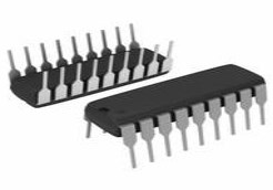
The package of AD9850 in PROTEL is DIP28.
 2N5109 NPN Transistor: Datasheet, 2N5109 RF Amplifier, Replacement
10 December 20216025
![TYN616 Thyristors SCRs 600V 16A TO-220AB[FAQ]: Pinout, Features, and Datasheet](https://res.utmel.com/Images/Article/d3c7ac52-c798-439a-843d-1bc66885c4d3.png) TYN616 Thyristors SCRs 600V 16A TO-220AB[FAQ]: Pinout, Features, and Datasheet
TYN616 Thyristors SCRs 600V 16A TO-220AB[FAQ]: Pinout, Features, and Datasheet04 May 20226473
 A76 Battery VS 357: Which battery to choose?
24 March 202226357
 TIP32C Power Transistor: Pinout, Datasheet, and Circuit
08 July 20219276
 TXS0104EPWR: Overview, Features, and Applications
21 December 2023720
 VO1400AEFTR:60v,pinout, datasheet and circuit
16 March 2022445
 SN74LVC1G14DBVR: Overview, Features, and Applications
20 November 2023344
 LM3914N Display Driver: Datasheet, Pinout and Comparison
02 August 20216821
 Improving the Energy Conversion Efficiency of Triboelectric Nanogenerators
19 November 20242466
 How does an Inverter Work?
06 April 20218344
 Core Components behind Smart Glasses
28 June 20239689
 Semiconductor Industry Poised for $1 Trillion Growth Opportunity by 2030
20 November 20232339
 Beginner’s Handbook for Choosing Circular Connectors
14 July 20251713
 Introduction to Lead Acid Battery: Construction, Working Principle and Types
04 March 20219354
 Introduction to Types of Oscillator Circuits
14 January 202614389
 Infrared Thermometer: How it Works? How to Use it?
12 August 20216960
Analog Devices Inc.
In Stock: 10
Minimum: 1 Multiples: 1
Qty
Unit Price
Ext Price
1
$14.205996
$14.21
10
$13.401883
$134.02
100
$12.643286
$1,264.33
500
$11.927628
$5,963.81
1000
$11.252479
$11,252.48
Not the price you want? Send RFQ Now and we'll contact you ASAP.
Inquire for More Quantity
![AD9834BRUZ]() AD9834BRUZ
AD9834BRUZAnalog Devices Inc.
![AD9850BRSZ]() AD9850BRSZ
AD9850BRSZAnalog Devices Inc.
![AD9832BRUZ]() AD9832BRUZ
AD9832BRUZAnalog Devices Inc.
![AD9834CRUZ]() AD9834CRUZ
AD9834CRUZAnalog Devices Inc.
![AD9833BRMZ-REEL7]() AD9833BRMZ-REEL7
AD9833BRMZ-REEL7Analog Devices Inc.
![AD9834BRUZ-REEL]() AD9834BRUZ-REEL
AD9834BRUZ-REELAnalog Devices Inc.
![AD5932YRUZ]() AD5932YRUZ
AD5932YRUZAnalog Devices Inc.
![AD9837BCPZ-RL7]() AD9837BCPZ-RL7
AD9837BCPZ-RL7Analog Devices Inc.
![AD9858BSVZ]() AD9858BSVZ
AD9858BSVZAnalog Devices Inc.
![AD9852ASVZ]() AD9852ASVZ
AD9852ASVZAnalog Devices Inc.


