

 Product
 Brand
Brand Articles
 Tools
Tools
TLE8209 8.6A H-Bridge Driver: Technical Datasheet, Pinout, and NRND Migration Analysis

3.25mm mm 11mm mm Motor Drivers 20 5V V 15.9mm mm
Unit Price: $4.351917
Ext Price: $4.35


3.25mm mm 11mm mm Motor Drivers 20 5V V 15.9mm mm
Optimize automotive DC motor control with the TLE8209 8.6A H-bridge. Get full specs, SPI pinout, and NRND migration tips. Design safety-critical systems today.
- Executive Summary: What is the TLE8209?
- 1. Technical Specifications & Performance Analysis
- 2. Pinout, Package, and Configuration
- 3. Design & Integration Guide
- 4. Typical Applications & Use Cases
- 5. Alternatives and Cross-Reference Guide
- 6. Frequently Asked Questions (FAQ)
- 7. Resources
- Specifications
- Parts with Similar Specs
- Datasheet PDF
Executive Summary: What is the TLE8209?
The TLE8209 is a SPI-programmable H-bridge driver specifically engineered by Infineon for the bidirectional control of DC motors in safety-critical automotive environments. It serves as a robust power stage for actuators requiring precise current control and extensive diagnostic feedback.
Market Position: High-reliability automotive grade; legacy industry standard for powertrain actuators.
Top Features: Programmable current limiting up to 8.6 A, wide 4.5 V to 28 V operating range, and integrated 16-bit SPI diagnostics.
Primary Audience: Automotive powertrain engineers, safety-critical system designers, and ECU hardware architects.
Supply Status: NRND (Not Recommended for New Designs). While still available for legacy support, new projects should evaluate migration paths.
1. Technical Specifications & Performance Analysis
1.1 Core Architecture (Power DMOS)
The TLE8209 utilizes a DMOS H-bridge architecture, integrating four power switches and their respective drive circuits into a single package. This "smart" power IC is designed to bridge the gap between a low-power microcontroller (MCU) and a high-current inductive load. The architecture is specifically hardened for ISO 26262 contexts, such as Electronic Throttle Control (ETC), where unintended motor movement must be prevented.
1.2 Key Electrical Characteristics
Performance is defined by its ability to handle high-current transients while maintaining low power dissipation. - Operating Battery Voltage: 4.5 V to 28 V (Supports start-stop cranking and 24V transients). - Logic Supply Voltage: 4.4 V to 5.25 V (Standard 5V CMOS compatibility). - Programmable Current Limit: 1.5 A to 8.6 A (typ.) via SPI, allowing one chip to be used across multiple motor platforms. - On-Resistance (RDSon): 240 mΩ (typ.) for the full path (High-side + Low-side), minimizing thermal overhead.
1.3 Interfaces and Connectivity
The TLE8209 communicates primarily via a 16-bit SPI (Serial Peripheral Interface). This interface is not just for configuration; it provides real-time diagnostic data including: - Short circuit to ground/battery detection. - Open load detection in ON and OFF states. - Overtemperature warning and shutdown status.
2. Pinout, Package, and Configuration
2.1 Pin Configuration Guide
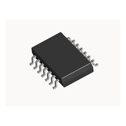
The TLE8209 is typically housed in high-power SMD packages (like the PG-DSO-20) to facilitate heat transfer to the PCB.
| Pin Group | Function | Description |
|---|---|---|
| Power | VS, GND | Main battery supply and power ground. |
| Logic | VCC, AGND | Logic supply and analog ground reference. |
| Output | OUT1, OUT2 | H-Bridge outputs to the DC motor. |
| Control | PWM, DIR | Hardware pins for speed (PWM) and direction (DIR). |
| SPI | CLK, CSN, DI, DO | Standard 4-wire SPI for configuration and diagnostics. |
| Safety | DIS | Disable pin for immediate hardware-level shutdown. |

2.2 Naming Convention & Ordering Codes
Infineon uses specific suffixes to denote package types and revisions.
- TLE8209-2E: Standard version in DSO-20 package.
- TLE8209-4SA: Enhanced thermal or logic variant (refer to specific revision history).
- Note for Procurement: Ensure the "E" or "SA" suffix matches your existing PCB footprint, as lead frame dimensions can vary slightly.
2.3 Available Packages
| Package Type | Dimensions | Common Use Case |
|---|---|---|
| PG-DSO-20 | 15.9 x 11 mm | Standard automotive ECU mounting; excellent thermal dissipation via heat slug. |
3. Design & Integration Guide
Pro Tip: When using the TLE8209 in safety-critical designs, implement a redundant "Watchdog" via the MCU to toggle the DIS (Disable) pin if SPI communication fails.
3.1 Hardware Implementation
Bypass Capacitors: Place a 100nF ceramic capacitor in parallel with a 47µF electrolytic capacitor as close to the VS pin as possible to suppress switching noise.
PCB Layout: Use a "Star Ground" strategy. Separate the Power Ground (PGND) from the Analog Ground (AGND) to prevent high-current motor noise from corrupting SPI data.
Thermal Management: The TLE8209 relies on the PCB copper as a heatsink. Use thermal vias under the exposed pad (if applicable) to pull heat to the bottom ground plane.
3.2 Common Design Challenges
Issue: Thermal derating at high ambient temperatures.
Fix: The TLE8209 features temperature-dependent current reduction. If the junction exceeds 165°C, the current limit drops linearly. To avoid performance loss, ensure your thermal resistance ($\theta_{JA}$) is kept below 30 K/W through optimized PCB copper pour.
Issue: SPI sharing in safety-critical systems.
Fix: Avoid sharing the SPI bus with high-speed sensors. Use a dedicated Chip Select (CSN) and ensure the MCU SPI clock phase (CPHA) and polarity (CPOL) match the TLE8209's 16-bit protocol.
4. Typical Applications & Use Cases
4.1 Real-World Example: Electronic Throttle Control (ETC)
In an ETC system, the TLE8209 drives the motor that opens the butterfly valve.
Input: The MCU receives data from the accelerator pedal sensor.
Control: The MCU sends PWM signals to the TLE8209 to position the valve.
3. Safety: The TLE8209 monitors the motor current. If the valve is jammed, the current limit triggers, and an error flag is sent via SPI, allowing the MCU to enter "Limp Home" mode.
5. Alternatives and Cross-Reference Guide
Given the NRND status of the TLE8209, engineers should consider the following migration paths:
Direct Upgrade (Infineon): TLE9201SG. This is the recommended successor, offering lower RDSon and improved SPI diagnostics in a smaller footprint.
High-Performance Alternative: STMicroelectronics L9960T. Offers advanced safety features and is widely used in modern Euro 6/7 powertrain systems.
Cost-Effective/Industrial: Texas Instruments DRV8873-Q1. Excellent integrated sensing and a smaller form factor for non-powertrain automotive apps.
6. Frequently Asked Questions (FAQ)
Q: Is the TLE8209 pin-compatible with the TLE9201SG?
A: No. While they perform similar functions, the package and pinout differ. A PCB redesign is required.
Q: Can it be used for 24V truck applications?
A: Yes, the 28V maximum rating covers 24V systems, though care must be taken regarding load-dump transients.
Q: How do I read the fault register?
A: Send a 16-bit SPI "Read" command. The device will shift out the status register on the MISO (DO) line during the next SPI frame.
7. Resources
Datasheet: Visit the Infineon website for the latest TLE8209-2E PDF.
Evaluation Kits: Look for the "TLE8209-2E Evaluation Board" for rapid prototyping with Arduino or STM32.
Simulation: SPICE models are available for thermal and electrical transient analysis.
Disclaimer: The TLE8209 is marked as NRND. Always consult with an authorized distributor for current lead times and end-of-life (EOL) notifications.
Specifications
Parts with Similar Specs
- ImagePart NumberManufacturerPackage / CaseNumber of PinsRoHS StatusFunctionECCN CodeLogic FunctionPart StatusMotor Type - AC, DCView Compare
![TLE82092SAAUMA1]()
TLE82092SAAUMA1
20-SOIC (0.433, 11.00mm Width) Exposed Pad
20
ROHS3 Compliant
Driver - Fully Integrated, Control and Power Stage
EAR99
AND
Active
Brushless DC (BLDC) Servo, Brushed DC Servo
![DRV8800RTYT]()
16-DIP (0.300, 7.62mm)
16
ROHS3 Compliant
Driver - Fully Integrated, Control and Power Stage
EAR99
AND
Active
Brushed DC
![L293NE]()
16-WQFN Exposed Pad
16
ROHS3 Compliant
Driver - Fully Integrated, Control and Power Stage
EAR99
AND
Active
Brushed DC
![L293DNE]()
16-DIP (0.300, 7.62mm)
16
ROHS3 Compliant
Driver - Fully Integrated, Control and Power Stage
EAR99
AND
Active
Brushed DC
![L293DNEE4]()
16-DIP (0.300, 7.62mm)
16
ROHS3 Compliant
Driver - Fully Integrated, Control and Power Stage
EAR99
AND
Active
Brushed DC


Datasheet PDF
- Datasheets :
- PCN Packaging :
- Other Related Documents :
- PCN Design/Specification :
- ConflictMineralStatement :
 PESD2CAN TVS Diode: SOT-23, CAN Bus, Datasheet and Pinout
16 February 20225105
 A1222 Sensor: Datasheet, Application, Function
23 August 2021753
 STM32WB55RGV7 vs STM32G4 Series Performance Comparison
07 June 2025538
![SI7201-B-05-IV MAGNETIC SWITCH OMNIPOL SOT23-3[FAQ]: Datasheet, Pinout, and Applications](https://res.utmel.com/Images/Article/711cc007-3bfa-4a59-b189-a4f28ce12b3e.jpg) SI7201-B-05-IV MAGNETIC SWITCH OMNIPOL SOT23-3[FAQ]: Datasheet, Pinout, and Applications
SI7201-B-05-IV MAGNETIC SWITCH OMNIPOL SOT23-3[FAQ]: Datasheet, Pinout, and Applications09 March 20221339
![MSP430 Mixed-Signal Microcontroller: MSP430 Features, Pinout and Datasheet [FAQ]](https://res.utmel.com/Images/Article/099de344-e17e-49b9-9c53-cfa31c7fa36e.jpg) MSP430 Mixed-Signal Microcontroller: MSP430 Features, Pinout and Datasheet [FAQ]
MSP430 Mixed-Signal Microcontroller: MSP430 Features, Pinout and Datasheet [FAQ]13 January 20224821
 TLV62568DRLT: Datasheet, Pinout, Step-down
12 February 2022968
 MIC2545A Programmable Current-Limit High-Side Switch: Pinout, Equivalent and Datasheet
29 March 2022793
 DW01A Battery Protection IC: Datasheet pdf, Schematic and Alternatives
19 November 202117751
 HDMI RF Modulators: Architecture, Setup, Types, and Commercial Applications
18 May 2026908
 MLCC: Applications and Future Development
20 December 202110574
 Understanding Electronic Speed Controllers (ESCs): Working Principles, Key Specifications, and Sourcing Guide
15 June 20261363
 MSL and Floor Life: A Receiving-to-Reflow Checklist for ICs
22 September 2026336
 sar-adc-reference-driver-selection-managing-dynamic-kickback-noise-loop-stability
17 September 2026463
 Introduction to the Types of SDRAM
13 July 202115086
 Sourcing GaN Power Devices for AI Servers, EVs, and Industrial Applications
10 July 2026382
 What is the Ripple of the Power Supply, How to Measure its Value, and How to Suppress it?
23 November 202110694
Infineon Technologies
In Stock
Minimum: 1 Multiples: 1
Qty
Unit Price
Ext Price
1
$4.351917
$4.35
10
$4.105582
$41.06
100
$3.873190
$387.32
500
$3.653953
$1,826.98
1000
$3.447126
$3,447.13
Not the price you want? Send RFQ Now and we'll contact you ASAP.
Inquire for More Quantity
![TLE62086GXUMA2]() TLE62086GXUMA2
TLE62086GXUMA2Infineon Technologies
![TLE4209GXUMA2]() TLE4209GXUMA2
TLE4209GXUMA2Infineon Technologies
![TLE4207GXUMA2]() TLE4207GXUMA2
TLE4207GXUMA2Infineon Technologies
![IRSM836-025MA]() IRSM836-025MA
IRSM836-025MAInfineon Technologies
![IR2238QPBF]() IR2238QPBF
IR2238QPBFInfineon Technologies
![TLE42062GXUMA2]() TLE42062GXUMA2
TLE42062GXUMA2Infineon Technologies
![TLE4205GXUMA1]() TLE4205GXUMA1
TLE4205GXUMA1Infineon Technologies
![TLE7184FXUMA2]() TLE7184FXUMA2
TLE7184FXUMA2Infineon Technologies
![TLE8444SLXUMA1]() TLE8444SLXUMA1
TLE8444SLXUMA1Infineon Technologies


