

 Product
 Brand
Brand Articles
 Tools
Tools
Thermal Management in AI Servers: Specifying Class 2 MLCCs (X7R/X7S) for Liquid Cooling Environments
Quick answer: As AI server racks move from air cooling to direct-to-chip cold plates and immersion cooling, the thermal environment around decoupling capacitors changes in ways that catch many designs off guard. Bulk junction temperatures drop, but localized gradients near cold plate edges and microchannel lids can fluctuate sharply during training bursts. This is why design engineers increasingly specify Class 2 MLCCs with X7R and X7S dielectrics (rated −55°C to +125°C) instead of X5R parts (rated only to +85°C) for power delivery networks on GPU baseboards and power shelves. X7R offers tighter capacitance stability (±15% over temperature); X7S trades a wider tolerance (±22%) for higher capacitance density in the same footprint — often the deciding factor when board space next to the processor is measured in millimeters.
Why liquid cooling changed the capacitor question
For most of the data center era, capacitor selection on server boards was a solved problem. Air-cooled systems had predictable airflow, component temperatures stayed comfortably inside X5R limits, and thermal margins were generous.
AI accelerators broke that assumption. With per-GPU power now commonly cited in the 700 W to 1,000 W+ range and rack densities pushing well past what air can dissipate, direct-to-chip (D2C) cold plates and immersion cooling have moved from exotic to mainstream. Schneider Electric, HPE, and Google Cloud have all published deployment guidance for single-phase direct liquid cooling in AI data centers over the past two years — a sign of how quickly this transition has become standard practice.
Here is the part that matters for passive component selection: liquid cooling lowers average temperatures but reshapes the thermal map.
Three effects stand out:
1. Reduced incidental airflow. In an air-cooled chassis, every component benefits from bulk airflow. Once the primary heat load moves into a coolant loop, fan capacity is often reduced or redistributed. Components not attached to cold plates — VRMs, memory power rails, and the MLCC arrays around them — may see less convective cooling than they did in the air-cooled design they were copied from. Industry coverage has started calling this the "hidden cooling bottleneck" of liquid-cooled AI systems, and it is exactly where decoupling capacitors live.
2. Steep localized gradients at cold plate edges. The board area directly under a cold plate runs cool. The perimeter — where MLCC banks typically sit to minimize loop inductance to the die — sees a sharp transition zone. During heavy LLM training bursts, transient power steps of hundreds of amps translate into rapid local temperature swings near the microchannel lids. A capacitor rated to 85°C with soft derating behavior above that point is a poor fit for this zone.
3. Mechanical stress from clamping and thermal cycling. Cold plate assemblies apply significant clamping pressure through thermal interface materials to maintain contact with the die. Ceramic is brittle. MLCCs adjacent to the clamped zone endure board flex and repeated thermal cycling, which raises the risk of flex cracks — a failure mode that can progress to a short circuit on a power rail. This is why flexible-termination (soft-termination) variants are worth considering for parts nearest the cold plate mounting points.
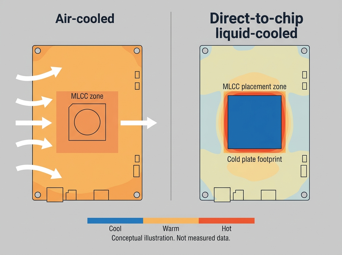
Liquid cooling lowers peak die temperature but creates a steep gradient at the cold plate perimeter — precisely where decoupling MLCCs are placed.
X5R vs X7R vs X7S: what the EIA codes actually tell you
The three-character EIA code encodes the rated temperature range and the maximum capacitance change over that range — nothing more. It says nothing about DC bias behavior, voltage rating, or aging, which is where many selection mistakes happen.
| Characteristic | X5R | X7R | X7S |
|---|---|---|---|
| Rated temperature range | −55°C to +85°C | −55°C to +125°C | −55°C to +125°C |
| Capacitance change over range | ±15% | ±15% | ±22% |
| Typical strength | Cost, high capacitance density | Best stability-to-density balance at 125°C rating | Highest capacitance density among 125°C-rated Class 2 options |
| Typical AI server role | Legacy / lower-stress rails | Core decoupling on GPU/CPU power rails, VRM output | Bulk decoupling where board space is critical |
| Main caution | 85°C ceiling is marginal near cold plate edges | Moderate DC bias derating — check curves | Wider TCC tolerance; verify effective capacitance at bias and temperature |
Two practical points behind the table:
The X5R problem is the ceiling, not the tolerance. X5R and X7R share the same ±15% specification — over their respective rated ranges. The issue in liquid-cooled AI hardware is that local hot zones can approach or exceed the 85°C boundary where X5R's rating simply ends. Operating a dielectric at or beyond its rated ceiling accelerates aging and erodes any margin your power integrity simulation assumed.
X7S is a density play, not a stability play. Compared with X7R, X7S accepts a wider capacitance window (±22%) in exchange for packing more capacitance into the same case size at the full 125°C rating. On a Rubin-class GPU baseboard where hundreds of capacitors compete for millimeters of real estate around the die, that volumetric efficiency is frequently the deciding constraint. If your PDN simulation has slack in effective capacitance, X7S buys you space; if the design is sensitive to capacitance variation, X7R keeps the tolerance band tighter.
The decision framework: matching dielectric to thermal zone
Rather than specifying one dielectric board-wide, it helps to segment the board into thermal zones and select accordingly.
Zone 1 — cold plate perimeter and microchannel lid proximity (highest stress). Sustained elevated temperatures, rapid transients during workload bursts, mechanical clamping stress nearby. Specify X7R or X7S with soft/flexible terminations. Verify effective capacitance at the actual rail voltage and the worst-case local temperature, not at datasheet nominal conditions.
Zone 2 — VRM and power shelf areas. High ripple current and self-heating on top of ambient. X7R is the common default here; check the manufacturer's ripple current guidance and thermal derating curves rather than assuming the temperature rating alone covers self-heating.
Zone 3 — general board areas with adequate residual airflow. Lower-stress rails may tolerate X5R on cost grounds, but confirm this against the measured (not assumed) airflow of the liquid-cooled chassis. A component copied from an air-cooled reference design inherits the old thermal assumption, not the new reality.
Immersion cooling adds its own gate. If the system is single-phase or two-phase immersion rather than D2C, every submerged component needs material compatibility validation with the dielectric fluid — termination finishes, coatings, and marking inks included. Fluid compatibility is a qualification question for the capacitor manufacturer and fluid vendor, not something to infer from the EIA code.
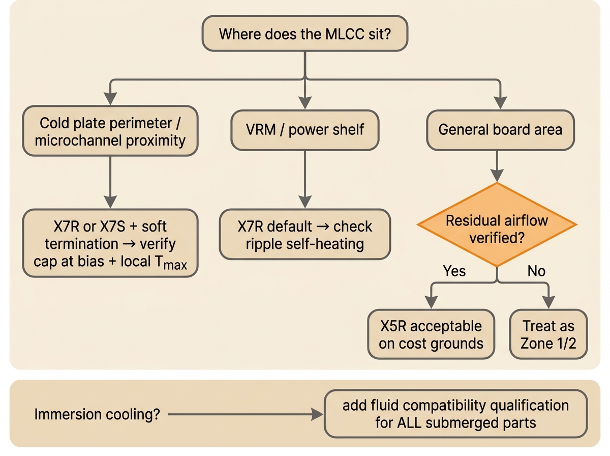
A zone-based selection flow prevents the two most common mistakes: over-specifying the whole board or under-specifying the cold plate edge.
Beyond temperature: DC bias, acoustic noise, and aging
Class 2 dielectrics are ferroelectric, and three of their behaviors matter more in AI servers than in almost any other application.
DC bias derating compounds with temperature. A Class 2 MLCC's effective capacitance drops as DC voltage is applied — sometimes dramatically. On 48 V distribution and the intermediate rails feeding GPU VRMs, a capacitor can deliver a fraction of its labeled capacitance. Temperature shift and bias derating stack. The only reliable approach is to pull the manufacturer's capacitance-vs-bias curve at the operating temperature and design the PDN around the effective value. Two "22 µF" parts from different vendors can differ meaningfully under identical bias conditions.
Acoustic noise (singing capacitors) tracks workload rhythm. The piezoelectric nature of Class 2 ceramics means voltage ripple in the audible band physically vibrates the capacitor and the board. AI training workloads are periodic — token batches, synchronization barriers, checkpoint cycles — which can concentrate ripple energy at specific frequencies and make boards audibly sing. In a dense rack this is more than an annoyance: sustained vibration adds mechanical fatigue. Mitigations include low-acoustic-noise MLCC variants, metal-terminal (lead-frame) constructions that decouple the ceramic body from the PCB, symmetric placement on both board sides to cancel flexure, and spreading capacitance across more, smaller parts.
Aging is a scheduled, predictable loss. Class 2 dielectrics lose a few percent of capacitance per decade-hour after their last heating above the Curie point. For servers designed to run at high utilization for five or more years, aging belongs in the end-of-life PDN margin calculation, not in a footnote.
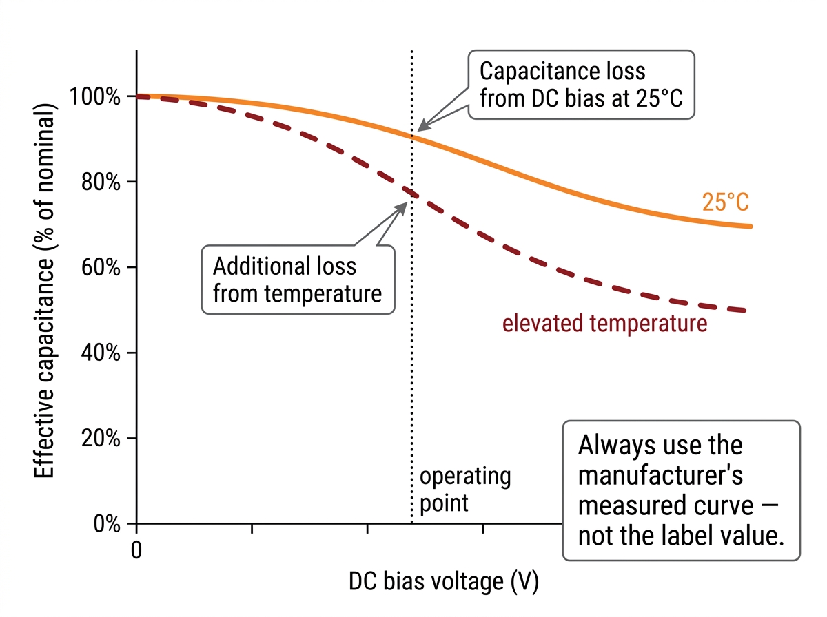
Labeled capacitance is a starting point, not a design value: bias and temperature effects stack, and curves differ between vendors.
Sourcing Class 2 MLCCs during a demand super-cycle
The same AI build-out driving liquid cooling adoption is straining the passive component supply chain. UTMEL's analysis of NVIDIA Rubin-class rack architectures estimates capacitor consumption at over 600,000 pieces per rack — and whatever the exact figure for any given configuration, the direction is clear: high-capacitance, high-temperature Class 2 parts are concentrated demand items. Their earlier deep-dive, AI Server MLCCs: Why NVIDIA Rubin Racks Require Over 600,000 Capacitors, walks through where those parts land on the power shelf and baseboard.
Three sourcing risks deserve attention in this environment:
Counterfeit remarking risk rises with spot prices. When high-temperature parts command a premium and extended lead times, the incentive appears to remark cheaper X5R stock as X7S. The two are visually identical. Externally, only traceability protects you: buy from franchised or authorized channels, demand full manufacturer lot codes and certificates of conformance, and for critical builds, consider incoming inspection with capacitance-versus-temperature verification on samples — an X5R masquerading as X7S reveals itself above 85°C.
Lead times and pricing are volatile — verify at order time. Extended lead times for specialized high-capacitance MLCCs have been widely reported during this cycle, but quoting any specific week count in a design document is a mistake; conditions shift quarter to quarter. Build schedule buffers, qualify second sources across at least two Tier-1 manufacturers early in the design phase, and lock allocations before board spins rather than after.
Cross-vendor "equivalents" are not automatic. Two parts sharing case size, capacitance, voltage, and dielectric code can still differ in DC bias curves, ESL, flex robustness, and acoustic behavior. Treat any substitution as a parametric review against both datasheets, not a line-item swap.
For teams sourcing under these constraints, UTMEL Electronics stocks original X7R ceramic capacitors and high-capacitance X7S MLCCs from Tier-1 manufacturers with full traceability, alongside the inductors and liquid cooling thermal pads that populate the same power delivery designs — useful when a build needs the whole BOM cluster from one accountable channel rather than piecemeal spot purchases.
The passive shortage is also intertwined with what is happening on the active side. Wide-bandgap power stages are raising switching frequencies and transient slew rates across AI power architectures, which feeds directly back into MLCC requirements — context covered in SiC and GaN in 2026: How SiC and GaN Power Devices Are Redefining AI Data Centers and 800V EVs.
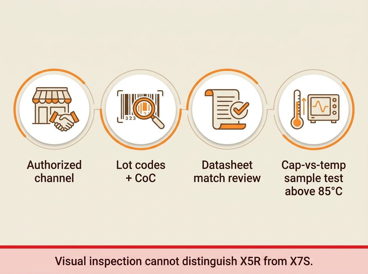
X5R and X7S parts look identical; only traceability and thermal verification separate them.
Common mistakes when moving a design from air to liquid cooling
Copying the air-cooled BOM. The most frequent failure path. The old design's X5R selections were validated against airflow that no longer exists.
Designing to labeled capacitance. Bias and temperature derating can leave a rail with far less effective decoupling than the schematic implies.
Ignoring the cold plate mechanical environment. Clamping stress and thermal cycling near mounting points call for soft-termination parts; standard terminations there invite flex cracks.
Treating immersion as "just better cooling." Submersion is a materials compatibility problem before it is a thermal one.
Qualifying a single source. In a constrained market, a sole-source Class 2 MLCC on a critical rail is a schedule risk hiding in the BOM.
Skipping acoustic evaluation. Periodic AI workloads excite audible ripple in ways synthetic load tests often miss; evaluate with representative training traffic.
FAQ
Do X7R and X7S have the same temperature range?Yes — both are rated −55°C to +125°C. The difference is the allowed capacitance change over that range: ±15% for X7R versus ±22% for X7S. X7S generally offers higher capacitance density in the same case size at the full 125°C rating.
Why not just use X5R if liquid cooling lowers temperatures?Liquid cooling lowers average and peak die temperatures, but it also reduces incidental airflow to board areas outside the cold plate and creates sharp gradients at the plate perimeter — where decoupling MLCCs sit. Local conditions there can approach X5R's 85°C ceiling, and operating a dielectric at its rating boundary erodes reliability margin.
Is X7S "better" than X7R?Neither is universally better. X7R holds a tighter capacitance window; X7S packs more capacitance into the same footprint at the same 125°C rating. Board-space-constrained bulk decoupling favors X7S; stability-sensitive rails favor X7R. Many AI baseboards use both.
Do MLCCs need special qualification for immersion cooling?Yes. Terminations, coatings, and markings must be validated for compatibility with the specific dielectric fluid. Confirm with both the capacitor manufacturer and the fluid vendor; the EIA temperature code says nothing about fluid exposure.
How can I tell if a "X7S" part is actually a remarked X5R?Not visually. Rely on authorized-channel sourcing, manufacturer lot traceability, and certificates of conformance. For critical builds, sample-test capacitance versus temperature: a genuine X7S holds its rating to 125°C, while a remarked X5R degrades past 85°C.
Does DC bias derating affect X7R and X7S equally?Both are Class 2 ferroelectric dielectrics and both derate under bias, but the curves vary significantly by manufacturer, case size, and voltage rating. Always compare the specific parts' measured bias curves at your operating voltage and temperature rather than assuming dielectric-code-level equivalence.
Final checklist before you freeze the BOM
Board segmented into thermal zones with measured or simulated local temperatures under liquid cooling — not inherited from the air-cooled design
Effective capacitance verified from manufacturer bias-and-temperature curves at each rail's actual operating point
Soft/flexible termination specified for MLCCs near cold plate clamping zones
Immersion fluid compatibility documented for every submerged part (if applicable)
Acoustic noise evaluated under representative AI workload patterns, with low-noise or metal-terminal variants identified as fallbacks
Aging derated into end-of-life PDN margin for the full service life
At least two qualified sources per critical Class 2 MLCC line item
All parts sourced through authorized channels with lot traceability and certificates of conformance; sample thermal verification planned for critical builds
Current lead times and pricing confirmed at order time, with schedule buffers for extended-lead-time items
Sources and references used for this guide
AI Server MLCCs: Why NVIDIA Rubin Racks Require Over 600,000 Capacitors (UTMEL)
Source type: Distributor technical blog Used for: Rubin-class rack capacitor demand context, X7R/X7S specification trend near liquid cooling microchannels, counterfeit remarking risk background
Caution: Distributor-authored; demand estimates and market figures reflect UTMEL's own analysis and should be treated as directional context rather than independent measurement.
Source type: Academic review paper Used for: MLCC functional roles in AI power delivery networks (noise suppression, peak current buffering, filtering), miniaturization and low-ESR/ESL requirements
Caution: Preprint-hosted copy; cross-check against the journal version where specific figures are quoted.
Single-phase direct liquid cooling for efficient AI data centers (Schneider Electric)
Source type: Vendor engineering blog Used for: Direct-to-chip liquid cooling deployment context and airflow-change implications for non-cold-plate components
Caution: Vendor content; used for technology description, not comparative product claims.
The Hidden Cooling Bottleneck Inside Liquid-Cooled AI Data Centers (All About Circuits)
Source type: Industry engineering publication Used for: The residual air-cooling problem for components outside the cold plate loop
Caution: Industry article format; sponsored-content provenance should be checked before quoting specific figures.
Source type: Peer-reviewed journal Used for: General evidence that liquid cooling reduces component temperatures and improves energy efficiency in AI workloads
Caution: Specific percentage results apply to the tested configuration and are not quoted as universal figures in this guide.
Direct Liquid Cooling solutions (HPE)
Source type: Vendor product page Used for: Confirmation of mainstream D2C liquid cooling availability in commercial AI server platforms
Caution: Marketing page; used only to establish technology adoption, not performance claims.
Component specifications, availability, and lead times change quickly during high-demand cycles. Verify all parameters against current manufacturer datasheets, and confirm stock and pricing with your distributor at order time. Browse in-stock X7R and X7S ceramic capacitors from Tier-1 manufacturers at UTMEL Electronics.
 UTMEL
UTMEL
We are the professional distributor of electronic components, providing a large variety of products to save you a lot of time, effort, and cost with our efficient self-customized service. careful order preparation fast delivery service
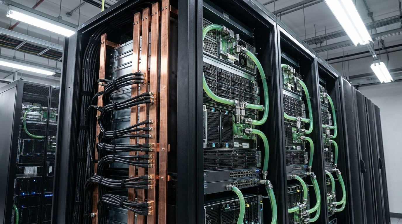 AI Server MLCCs: Why NVIDIA Rubin Racks Require Over 600,000 CapacitorsUTMEL02 June 20263605
Next-generation AI servers like NVIDIA's Rubin architecture require over 600,000 MLCCs per rack due to extreme power densities exceeding 120kW. This transition from GB300 demands high-capacitance, low-ESR capacitors with X7R/X7S dielectrics to handle intense transient responses and thermal loads, forcing procurement teams to navigate extended 24-week lead times for these specialized components.
Read More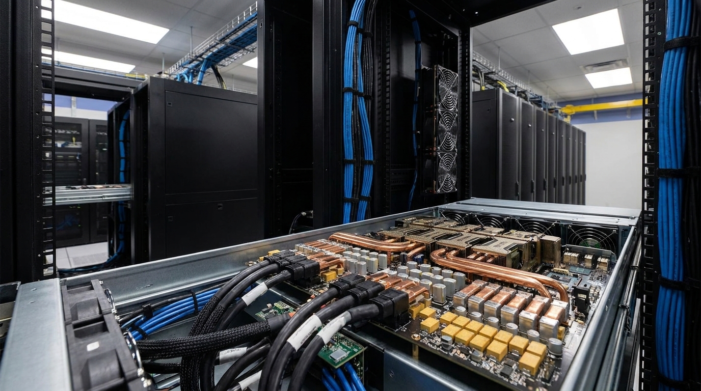 MLCC vs Polymer Tantalum Capacitors: Overcoming 2026 Shortages in AI Server PDNsUTMEL07 August 2026776
Facing 2026 MLCC lead times of up to 24 weeks driven by AI server demand, hardware engineers are substituting multi-layer ceramic capacitors with conductive polymer tantalum capacitors. While Class II MLCCs suffer severe DC bias capacitance loss and acoustic noise, polymer tantalums offer voltage stability and low ESR. Implementing a division-of-labor strategy—using polymer tantalums for bulk decoupling and MLCCs for point-of-load—optimizes PDN performance and bypasses supply bottlenecks.
Read More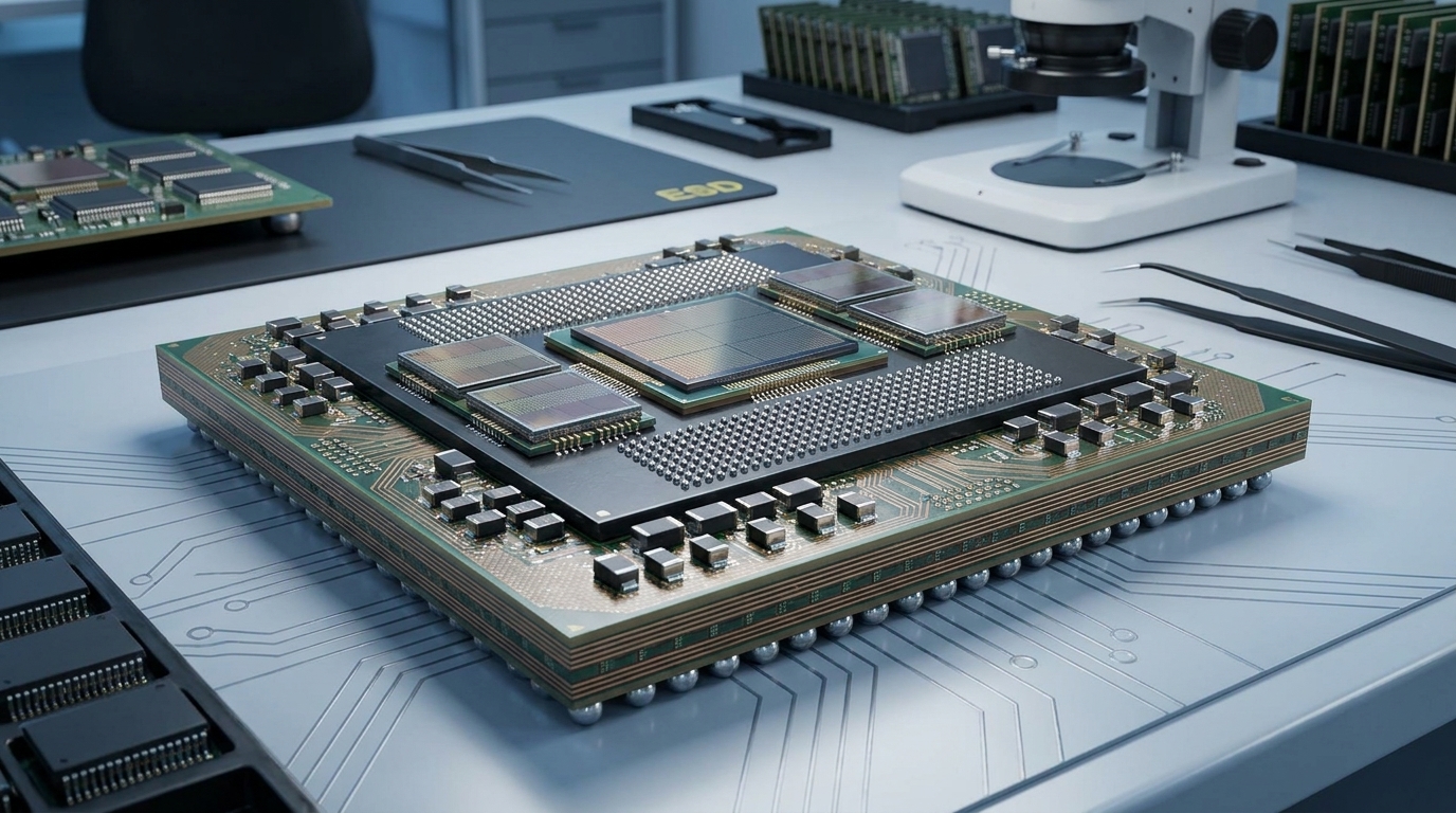 Sourcing Silicon Capacitors and MLCCs in the AI Hardware EraUTMEL13 August 2026652
Modern AI hardware requires a hybrid Power Delivery Network (PDN) to maintain low-voltage stability under extreme transient currents. Deep Trench Silicon Capacitors (DTCs) integrate directly into advanced packages to deliver ultra-low ESL and stable performance for high-frequency transient suppression. Meanwhile, Multilayer Ceramic Capacitors (MLCCs) provide essential bulk energy storage on the motherboard, making both technologies complementary across the AI power stack.
Read More MLCC DC Bias Derating: How to Calculate and Compare Effective Capacitance Before Component SelectionUTMEL11 September 2026661
Class II ceramic capacitors suffer significant capacitance loss under DC voltage due to ferroelectric domain saturation and high electric field intensity. This comprehensive engineering guide explains how to calculate true worst-case effective capacitance by compounding DC bias, temperature, tolerance, and aging. It provides multi-vendor simulation workflows, benchtop impedance measurement techniques, and practical guidelines to maintain power supply stability and avoid costly design failures.
Read More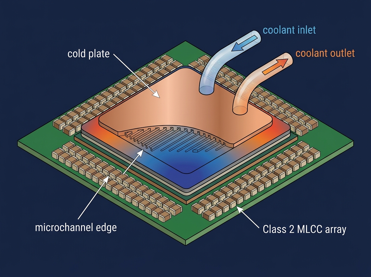 Thermal Management in AI Servers: Specifying Class 2 MLCCs (X7R/X7S) for Liquid Cooling EnvironmentsUTMEL13 July 2026435
Explore how the transition from traditional air-cooling to liquid cooling (direct-to-chip and immersion) in high-density AI server racks alters component thermal profiles. Focus on why design engineers are increasingly specifying Class 2 MLCCs (X7R and X7S dielectrics) over standard X5R variants to prevent thermal degradation near the liquid cooling microchannels. Explain how these capacitors mitigate acoustic noise and voltage bias degradation under heavy workloads. Provide sourcing advice for high-reliability passives via UTMEL during this high-demand memory and passive component super-cycle.
Read More
Subscribe to Utmel !
![MIKROE-4905]() MIKROE-4905
MIKROE-4905MikroElektronika
![STEVAL-CCA058V1]() STEVAL-CCA058V1
STEVAL-CCA058V1STMicroelectronics
![DEV-18721]() DEV-18721
DEV-18721SparkFun Electronics
![MIKROE-4915]() MIKROE-4915
MIKROE-4915MikroElektronika
![MIKROE-4888]() MIKROE-4888
MIKROE-4888MikroElektronika
![MIKROE-4828]() MIKROE-4828
MIKROE-4828MikroElektronika
![EVAL-ADUM4165EBZ]() EVAL-ADUM4165EBZ
EVAL-ADUM4165EBZAnalog Devices Inc.
![FSP-PIC18-Q10-ISO26262]() FSP-PIC18-Q10-ISO26262
FSP-PIC18-Q10-ISO26262Microchip Technology
![FBP-PIC16F184XX-ISO26262]() FBP-PIC16F184XX-ISO26262
FBP-PIC16F184XX-ISO26262Microchip Technology
![LPC5536-EVK]() LPC5536-EVK
LPC5536-EVKNXP USA Inc.
