
 Product
 Brand
Brand Articles
 Tools
Tools
What is An Optoisolator?
Digital Electronics: Optocoupler | Optoisolator - Driving a high-current CREE XLamp XR-C LED
Catalog
| I. Working principle |
| II. Types |
| III. Applications |
I. Working principle
The optoisolator mainly uses the Faraday effect of the magneto-optical crystal. The Faraday effect is the first observation by Faraday in 1845 that a non-optically active material rotates the polarization direction of light passing through the material under the action of a magnetic field. It is also called the magneto-optical rotation effect. For polarized light transmitted in the direction of the magnetic field, the rotation angle θ of the polarization direction and the product of the magnetic field strength B and the material length L are proportional.
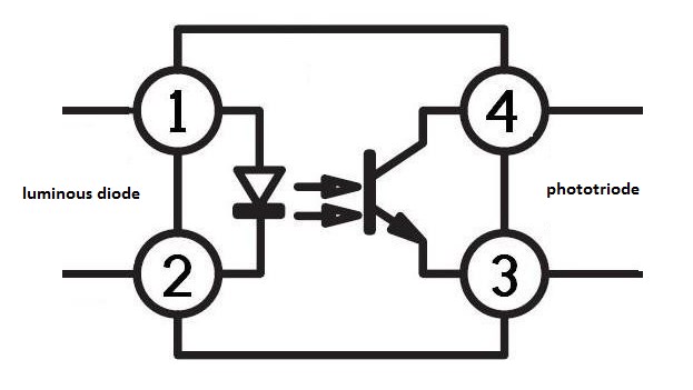
When the input electrical signal is applied to the input light-emitting device LED, the LED emits light, the light receiving device receives the light signal and converts it into an electrical signal, and then directly outputs the electrical signal, or amplifies the electrical signal to a standard digital level output, so that The conversion and transmission of "electricity-optical-electricity" are realized. Light is the transmission medium, so the input end and the output end are electrically insulated, which is also called electrical isolation.
For the signal light incident in the forward direction, it becomes linearly polarized light after passing through the polarizer. Together with the external magnetic field, the Faraday gyromagnetic medium rotates the polarization direction of the signal light by 45 degrees to the right, and makes the low loss pass and the polarizer 45 degrees. Degree of analyzer placed. For reverse light, when the linearly polarized light exiting the analyzer passes through the placement medium, the deflection direction is also rotated 45 degrees to the right, so that the polarization direction of the reverse light is orthogonal to the direction of the polarizer, completely blocking the transmission of reflected light.
Faraday's magnetic medium usually uses yttrium iron garnet (YIG) single crystal with low optical loss in the wavelength range of 1 μm to 2 μm. The optoisolator with the new pigtail input and output has quite good performance, the lowest insertion loss is about 0.5dB, the isolation is 35-60dB, and the highest can reach 70dB.
The signal transmitted by the optoisolator can be a digital signal or an analog signal, but the requirements for the device are different, so the corresponding optoisolator should be selected for the input signal. The optoisolator used for analog signals is often called a linear optoisolator. The principle of signal transmission is the same as the isolation transformer, but it is small in size, high in transmission frequency, and easy to use. Optoisolators are generally DIP packaged.
The light-emitting device of the optoisolator used to transmit analog signals is a diode, and the light receiver is a photosensitive triode. When a current flows through the light-emitting diode, a light source is formed. The light source illuminates the surface of the phototransistor, causing the phototransistor to generate collector current. The magnitude of the current is related to the intensity of the light, that is, the forward current flowing through the diode. The size is proportional. Since the optical signal is transmitted between the input end and the output end of the optoisolator, the two parts are electrically isolated completely without feedback and interference of electrical signals, so the performance is stable and the anti-interference ability is strong. The coupling capacitance between the luminous tube and the photosensitive tube is small (about 2pf), and the withstand voltage is high (about 2.5KV), so the common-mode rejection ratio is very high. The electrical isolation between input and output depends on the insulation resistance between the two parts of the power supply. In addition, because of its low input resistance (about 10Ω), the noise to the high internal resistance source is equivalent to being shorted. Therefore, the analog signal isolation circuit composed of optoisolators has excellent electrical performance.
In fact, the optoisolator is a current transfer device controlled by photocurrent. Its output characteristics are similar to those of ordinary bipolar transistors. Therefore, it can be used as an ordinary amplifier to directly form an analog amplifier circuit, and the input and output Can achieve electrical isolation. However, this kind of amplifier circuit has poor working stability and is of no practical value. There are two main reasons for this: First, the linear working range of the optoisolator is narrow, and changes with temperature; the second is the common-emitter current transfer coefficient β of the optoisolator and the collector reverse saturation current ICBO (ie dark Current) is obviously affected by temperature changes. Therefore, in practical applications, in addition to choosing an optoisolator with a wide linear range and high linearity to achieve analog signal isolation, effective measures must also be taken on the circuit to minimize the impact of temperature changes on the working state of the amplifier circuit.
It can be seen from the relationship between the transfer characteristics of the optoisolator and the temperature that if the analog isolation circuit formed by the optoisolator is stable and practical, the effect of dark current (ICBO) should be eliminated as much as possible to improve linearity and achieve a static operating point IFQ automatically adjusts with temperature changes to keep the output signal symmetrical, and the dynamic range of the input signal changes automatically with temperature changes to offset the effect of the β value with temperature changes and ensure the stability of the circuit's working state.
II. Types
As there are many varieties and types of optoisolators, they can usually be classified as follows:
1. According to the optical path, it can be divided into an external optical path optoisolator (also known as photoelectric interruption detector) and internal optical path optoisolator.
2. According to the output form, it can be divided into:
(1) Photosensitive device output type, including photodiode output type, phototransistor output type, photocell output type, phototriac output type, etc.
(2) NPN triode output type, including AC input type, DC input type, complementary output type, etc.
(3) Darlington transistor output type, including AC input type and DC input type.
(4) Logic gate circuit output type, including gate circuit output type, Schmitt trigger output type, tri-state gate circuit output type, etc.
(5) low-conduction output type (output low-level millivolts).
(6) optical switch output type (on-resistance is less than 10Ω).
(7) power output type (IGBT/MOSFET, etc. output).
3. According to the package type, it can be divided into coaxial type, dual in-line type, TO package type, flat package type, chip package type, and optical fiber transmission type.
4. According to the transmission signal, it can be divided into digital optoisolator (OC gate output type, totem pole output type and tri-state gate circuit output type, etc.) and linear optoisolator (can be divided into low drift type, high linearity Type, broadband type, single power supply type, dual power supply type, etc.).
5. According to speed, it can be divided into low-speed optoisolator (optoisolator, photocell, etc. output type) and high-speed optoisolator (photodiode with signal processing circuit or photosensitive integrated circuit output type).
6. According to the channel, it can be divided into a single channel, dual-channel, and multi-channel optoisolator.
7. According to the isolation characteristics, it can be divided into ordinary isolation optoisolators (generally optical glue potting is less than 5000V, and the empty seal is less than 2000V) and high voltage isolation optoisolators (can be divided into 10kV, 20kV, 30kV, etc.).
8. According to the working voltage, it can be divided into low power supply voltage type optoisolator (generally 5~15V) and high power supply voltage type optoisolator (generally greater than 30V).
III. Applications
(1) Application in the logic circuit
Optoisolators can form various logic circuits. Since the anti-interference performance and isolation performance of optoisolators are better than transistors, the logic circuits formed by them are more reliable.
(2) As a solid switch application
In the switch circuit, it is often required to have good electrical isolation between the control circuit and the switch, which is difficult to achieve for general electronic switches, but it is easy to achieve with an optoisolator.
(3) Application in the trigger circuit
The optoisolator is used in the bistable output circuit because the light-emitting diodes can be connected in series to the two emitter loops, which can effectively solve the problem of output and load isolation.
(4) Application in the pulse amplifier circuit
Optoisolators are used in digital circuits to amplify pulse signals.
(5) Application in linear circuit
Linear optoisolators are used in linear circuits and have high linearity and excellent electrical isolation performance.
(6) Application on special occasions
Optoisolators can also be used in high-voltage control, replacing transformers, replacing contact relays, and used in A/D circuits and other occasions.
 UTMEL
UTMEL
We are the professional distributor of electronic components, providing a large variety of products to save you a lot of time, effort, and cost with our efficient self-customized service. careful order preparation fast delivery service
What is difference between optocoupler and opto isolator?
An optocoupler also called opto-isolator, photocoupler, or optical isolator is a component that transfers electrical signals between two isolated circuits by using light. A digital CMOS isolator is a component that transfers electrical signals between two isolated circuits by using a high-frequency carrier.
How to test optoisolator?
(1) Part's Required: Multimeter or ohm meter, opto-coupler,100 Ohm resistor,push button,battery or power supply. (2) Turn ON multimeter and select Resistance mode. - Now, Connect the multimeter ( X1K Ohm or X10K Ohm ) between emitter and collector like this: red probe to collector and black probe to emitter. - Now, connect a resistor of a few hundred ohms (100 ohms) in series with the LED anode, after this turn on the power supply, press the push button and start increasing the voltage from 0 to 2…5 volts, and you should be able to see on the ohmmeter how the output resistance decreases as the input voltage increases and viceversa. - the optoisolator IC is Good. else if the optoisolator IC is Bad.
How do I choose an optoisolator?
Start by choosing a "gate drive" push-pull optoisolator and you almost can't go wrong. I would choose one with a supply voltage of 30 volts or so to give yourself some margin running a motor. You may need a resistor on the input side to limit diode current.
Why is optoisolator used in SMPS?
Optoisolators are frequently used in isolated switch-mode power supplies (SMPS) for galvanic separation between the primary and secondary sides as well as from the feedback generator.
 What is a Great Choice for Digital Isolators to Build Isolation Barriers?UTMEL31 March 20225243
Hello everyone, I am Rose. Welcome to the new post today. A digital isolator is a chip that has high resistance isolation characteristics when digital signals and analog signals are transmitted in an electronic system to realize the isolation between the electronic system and the user. and capacitive isolation to achieve.
Read More How to Select a Digital Isolator?UTMEL12 April 20217136
A digital isolator is a chip used to make the electronic system have high resistance isolation when signals and analog signals are transmitted, so as to realize the isolation between the electronic system and its users. The reason why designers introduce isolation is to meet safety regulations or reduce ground loop noise.
Read More Vibration Isolator: Types and ApplicationsUTMEL13 January 202112697
A vibration isolator is an elastic element connecting equipment and foundation to reduce and eliminate the vibration force transmitted from the equipment to the foundation and the vibration transmitted from the foundation to the equipment. This article will introduce some of the types of vibration isolators and their applications to you.
Read More What is An Optoisolator?UTMEL09 January 20218404
An optoisolator, also called optical coupler, optocoupler, and opto-isolator, is a device that encapsulates the infrared light-emitting device, the infrared light receiving device, and the signal processing circuit in the same tube socket.
Read More
Subscribe to Utmel !
