6N138 Optocouplers: Features, Pinout, and Datasheet
OPTOISO 5KV DARL W/BASE 8DIP
The 6N138 optocouplers consist of an AlGaAs LED optically coupled to a high gain split Darlington photodetector. This article mainly introduces features, pinout, datasheet and other detailed information about ON Semiconductor 6N138.

MIDI Opto Isolators, 6N138 and 4N25
6N138 Description
The 6N138 optocouplers consist of an AlGaAs LED optically coupled to a high gain split Darlington photodetector. With a split Darlington phototransistor optocoupler, the input photodiode and first stage gain are separated from the output transistor, allowing for lower output saturation voltage and faster operation than with a normal Darlington phototransistor optocoupler.
The combination of a low input current of 0.5mA and a high current transfer ratio of 2000 percent makes this family ideal for input interface to MOS, CMOS, LSTTL, and EIA RS232C, while output compatibility with CMOS and high fan-out TTL needs is ensured. A 10 kV/s common-mode rejection is achieved thanks to an inbuilt noise shield.
6N138 Pinout
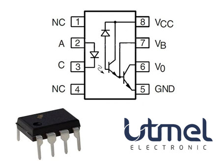
Pinout
6N138 CAD Model
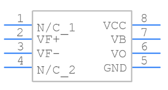
Symbol
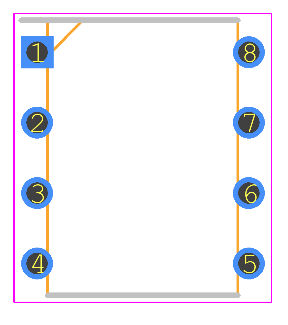
Footprint
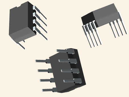
3D Model
6N138 Features
• Low current – 0.5mA
• Superior CTR-2000%
• Superior CMR-10kV/μs
• CTR guaranteed 0–70°C
• U.L. recognized (File # E90700)
• VDE recognized (File # 120915) Ordering option V, e.g., 6N138V
• Dual Channel – HCPL2730, HCPL2731
Specifications
- TypeParameter
- Lifecycle Status
Lifecycle Status refers to the current stage of an electronic component in its product life cycle, indicating whether it is active, obsolete, or transitioning between these states. An active status means the component is in production and available for purchase. An obsolete status indicates that the component is no longer being manufactured or supported, and manufacturers typically provide a limited time frame for support. Understanding the lifecycle status is crucial for design engineers to ensure continuity and reliability in their projects.
ACTIVE (Last Updated: 11 hours ago) - Factory Lead Time5 Weeks
- Contact Plating
Contact plating (finish) provides corrosion protection for base metals and optimizes the mechanical and electrical properties of the contact interfaces.
Tin - Mount
In electronic components, the term "Mount" typically refers to the method or process of physically attaching or fixing a component onto a circuit board or other electronic device. This can involve soldering, adhesive bonding, or other techniques to secure the component in place. The mounting process is crucial for ensuring proper electrical connections and mechanical stability within the electronic system. Different components may have specific mounting requirements based on their size, shape, and function, and manufacturers provide guidelines for proper mounting procedures to ensure optimal performance and reliability of the electronic device.
Through Hole - Mounting Type
The "Mounting Type" in electronic components refers to the method used to attach or connect a component to a circuit board or other substrate, such as through-hole, surface-mount, or panel mount.
Through Hole - Package / Case
refers to the protective housing that encases an electronic component, providing mechanical support, electrical connections, and thermal management.
8-DIP (0.300, 7.62mm) - Number of Pins8
- Supplier Device Package
The parameter "Supplier Device Package" in electronic components refers to the physical packaging or housing of the component as provided by the supplier. It specifies the form factor, dimensions, and layout of the component, which are crucial for compatibility and integration into electronic circuits and systems. The supplier device package information typically includes details such as the package type (e.g., DIP, SOP, QFN), number of pins, pitch, and overall size, allowing engineers and designers to select the appropriate component for their specific application requirements. Understanding the supplier device package is essential for proper component selection, placement, and soldering during the manufacturing process to ensure optimal performance and reliability of the electronic system.
8-DIP - Weight891mg
- Current Transfer Ratio-Min300% @ 1.6mA
- Number of Elements1
- Operating Temperature
The operating temperature is the range of ambient temperature within which a power supply, or any other electrical equipment, operate in. This ranges from a minimum operating temperature, to a peak or maximum operating temperature, outside which, the power supply may fail.
-40°C~100°C - Packaging
Semiconductor package is a carrier / shell used to contain and cover one or more semiconductor components or integrated circuits. The material of the shell can be metal, plastic, glass or ceramic.
Tube - Published2014
- Part Status
Parts can have many statuses as they progress through the configuration, analysis, review, and approval stages.
Active - Moisture Sensitivity Level (MSL)
Moisture Sensitivity Level (MSL) is a standardized rating that indicates the susceptibility of electronic components, particularly semiconductors, to moisture-induced damage during storage and the soldering process, defining the allowable exposure time to ambient conditions before they require special handling or baking to prevent failures
1 (Unlimited) - Max Operating Temperature
The Maximum Operating Temperature is the maximum body temperature at which the thermistor is designed to operate for extended periods of time with acceptable stability of its electrical characteristics.
100°C - Min Operating Temperature
The "Min Operating Temperature" parameter in electronic components refers to the lowest temperature at which the component is designed to operate effectively and reliably. This parameter is crucial for ensuring the proper functioning and longevity of the component, as operating below this temperature may lead to performance issues or even damage. Manufacturers specify the minimum operating temperature to provide guidance to users on the environmental conditions in which the component can safely operate. It is important to adhere to this parameter to prevent malfunctions and ensure the overall reliability of the electronic system.
-40°C - Max Power Dissipation
The maximum power that the MOSFET can dissipate continuously under the specified thermal conditions.
100mW - Base Part Number
The "Base Part Number" (BPN) in electronic components serves a similar purpose to the "Base Product Number." It refers to the primary identifier for a component that captures the essential characteristics shared by a group of similar components. The BPN provides a fundamental way to reference a family or series of components without specifying all the variations and specific details.
6N138 - Voltage - Isolation
Voltage - Isolation is a parameter in electronic components that refers to the maximum voltage that can be safely applied between two isolated points without causing electrical breakdown or leakage. It is a crucial specification for components such as transformers, optocouplers, and capacitors that require isolation to prevent electrical interference or safety hazards. The voltage isolation rating ensures that the component can withstand the specified voltage without compromising its performance or safety. It is typically measured in volts and is an important consideration when designing circuits that require isolation between different parts of the system.
5000Vrms - Output Type
The "Output Type" parameter in electronic components refers to the type of signal or data that is produced by the component as an output. This parameter specifies the nature of the output signal, such as analog or digital, and can also include details about the voltage levels, current levels, frequency, and other characteristics of the output signal. Understanding the output type of a component is crucial for ensuring compatibility with other components in a circuit or system, as well as for determining how the output signal can be utilized or processed further. In summary, the output type parameter provides essential information about the nature of the signal that is generated by the electronic component as its output.
Darlington with Base - Number of Channels1
- Power Dissipation
the process by which an electronic or electrical device produces heat (energy loss or waste) as an undesirable derivative of its primary action.
100mW - Voltage - Forward (Vf) (Typ)
The parameter "Voltage - Forward (Vf) (Typ)" in electronic components refers to the typical forward voltage drop across the component when it is conducting current in the forward direction. It is a crucial characteristic of components like diodes and LEDs, indicating the minimum voltage required for the component to start conducting current. The forward voltage drop is typically specified as a typical value because it can vary slightly based on factors such as temperature and manufacturing tolerances. Designers use this parameter to ensure that the component operates within its specified voltage range and to calculate power dissipation in the component.
1.3V - Input Type
Input type in electronic components refers to the classification of the signal or data that a component can accept for processing or conversion. It indicates whether the input is analog, digital, or a specific format such as TTL or CMOS. Understanding input type is crucial for ensuring compatibility between different electronic devices and circuits, as it determines how signals are interpreted and interacted with.
DC - Forward Current
Current which flows upon application of forward voltage.
20mA - Max Output Voltage
The maximum output voltage refers to the dynamic area beyond which the output is saturated in the positive or negative direction, and is limited according to the load resistance value.
7V - Data Rate
Data Rate is defined as the amount of data transmitted during a specified time period over a network. It is the speed at which data is transferred from one device to another or between a peripheral device and the computer. It is generally measured in Mega bits per second(Mbps) or Mega bytes per second(MBps).
100 kbps - Output Current per Channel
Output Current per Channel is a specification commonly found in electronic components such as amplifiers, audio interfaces, and power supplies. It refers to the maximum amount of electrical current that can be delivered by each individual output channel of the component. This parameter is important because it determines the capacity of the component to drive connected devices or loads. A higher output current per channel means the component can deliver more power to connected devices, while a lower output current may limit the performance or functionality of the component in certain applications. It is crucial to consider the output current per channel when selecting electronic components to ensure they can meet the power requirements of the intended system or setup.
60mA - Rise Time
In electronics, when describing a voltage or current step function, rise time is the time taken by a signal to change from a specified low value to a specified high value.
35μs - Forward Voltage
the amount of voltage needed to get current to flow across a diode.
1.7V - Fall Time (Typ)
Fall Time (Typ) is a parameter used to describe the time it takes for a signal to transition from a high level to a low level in an electronic component, such as a transistor or an integrated circuit. It is typically measured in nanoseconds or microseconds and is an important characteristic that affects the performance of the component in digital circuits. A shorter fall time indicates faster switching speeds and can result in improved overall circuit performance, such as reduced power consumption and increased data transmission rates. Designers often consider the fall time specification when selecting components for their circuits to ensure proper functionality and efficiency.
10 μs - Reverse Breakdown Voltage
Reverse Breakdown Voltage is the maximum reverse voltage a semiconductor device can withstand before it starts to conduct heavily in the reverse direction. It is a critical parameter in diodes and other components, indicating the threshold at which the material's insulating properties fail. Beyond this voltage, the device may enter a breakdown region, leading to potential damage if not properly managed. This parameter is essential for ensuring safe operation and reliability in electronic circuits.
5V - Max Input Current
Max Input Current is a parameter that specifies the maximum amount of electrical current that can safely flow into an electronic component without causing damage. It is an important consideration when designing or using electronic circuits to ensure that the component operates within its specified limits. Exceeding the maximum input current can lead to overheating, component failure, or even pose safety risks. Manufacturers provide this parameter in datasheets to help engineers and users understand the limitations of the component and ensure proper operation within the specified parameters.
20mA - Current - DC Forward (If) (Max)
The parameter "Current - DC Forward (If) (Max)" in electronic components refers to the maximum forward current that can safely pass through the component without causing damage. This parameter is typically specified in datasheets for diodes and LEDs, indicating the maximum current that can flow through the component in the forward direction. Exceeding this maximum current rating can lead to overheating and potentially permanent damage to the component. It is important to ensure that the current flowing through the component does not exceed this specified maximum to maintain proper functionality and reliability.
20mA - Turn On / Turn Off Time (Typ)
Turn On / Turn Off Time (Typ) in electronic components refers to the time it takes for a device to switch from a non-conducting state to a conducting state (Turn On) and vice versa (Turn Off). This parameter is crucial for understanding the speed and responsiveness of the component in switching applications. It typically indicates the average time under specified conditions and is essential for optimizing the performance in circuits where rapid switching is required, such as in power electronics and digital logic devices.
1μs, 7.3μs - Current Transfer Ratio
Current Transfer Ratio (CTR) is the gain of the optocoupler. It is the ratio of the phototransistor collector current to the IRED forward current. CTR = (IC / IF) * 100 It is expressed as a percentage (%).
1600 % - Radiation Hardening
Radiation hardening is the process of making electronic components and circuits resistant to damage or malfunction caused by high levels of ionizing radiation, especially for environments in outer space (especially beyond the low Earth orbit), around nuclear reactors and particle accelerators, or during nuclear accidents or nuclear warfare.
No - RoHS Status
RoHS means “Restriction of Certain Hazardous Substances” in the “Hazardous Substances Directive” in electrical and electronic equipment.
ROHS3 Compliant
Parts with Similar Specs
- ImagePart NumberManufacturerPackage / CaseNumber of PinsNumber of ChannelsVoltage - IsolationCurrent Transfer RatioCurrent Transfer Ratio (Min)Rise TimeMax Output VoltageForward VoltageView Compare
6N138M
8-DIP (0.300, 7.62mm)
8
1
5000Vrms
1600 %
300% @ 1.6mA
35 μs
7 V
1.7 V
8-DIP (0.300, 7.62mm)
8
-
3750Vrms
-
-
50 ns
-
-
8-DIP (0.300, 7.62mm)
8
1
5300Vrms
2000 %
500% @ 1.6mA
60 μs
18 V
1.4 V
6N138 Schematic
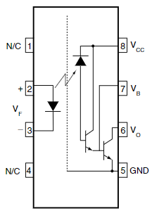
Schematic
6N138 Test Circuits

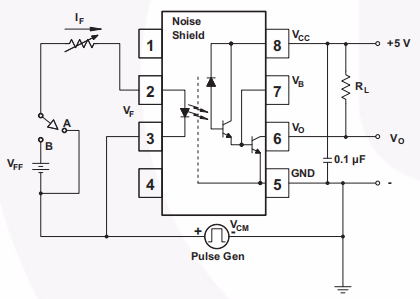
Test Circuits
6N138 vs 6N139
With a 2.2 k pull-up resistor, the 6N138 is appropriate for TTL applications since it has a 300 percent minimum current transfer ratio and an LED current of 1.6 mA, allowing operation with one unit load-in and one unit load-out. The 6N139 is best used in CMOS and TTL logic applications that require little power.
6N138 Alternatives
| Part Number | Description | Manufacturer |
| HCPL-4562#020OPTOELECTRONICS | Linear IC Output Optocoupler, 1-Element, 5000V Isolation, 0.300 INCH, DIP-8 | Agilent Technologies Inc |
| HCPL-0466-500EOPTOELECTRONICS | Logic IC Output Optocoupler, 1-Element, 3750V Isolation, LEAD FREE, SOP-8 | Broadcom Limited |
| PS8601-AOPTOELECTRONICS | Logic IC Output Optocoupler, 1-Element, 5000V Isolation, PLASTIC, DIP-8 | NEC Compound Semiconductor Devices Ltd |
| HCPL-0452#500OPTOELECTRONICS | Logic IC Output Optocoupler, 1-Element, 2500V Isolation, 1MBps, SO-8 | Hewlett Packard Co |
| HCPL-0501.R1OPTOELECTRONICS | Logic IC Output Optocoupler, 1-Element, 2500V Isolation, 1MBps, SOP-8 | Fairchild Semiconductor Corporation |
| HCPL-0453#060OPTOELECTRONICS | 1 CHANNEL LOGIC OUTPUT OPTOCOUPLER, 1Mbps, SOP-8 | Avago Technologies |
| HCPL-0452OPTOELECTRONICS | 1 CHANNEL LOGIC OUTPUT OPTOCOUPLER, 1 Mbps, LEAD FREE, SOIC-8 | Fairchild Semiconductor Corporation |
| HCPL2530OPTOELECTRONICS | 8-Pin DIP 1Mbit/s Dual-Channel High Speed Transistor Output Optocoupler (Not recommend for new design. The new equivalent part number is HCPL253xM), 1000-TUBE | onsemi |
| 4N46-500EOPTOELECTRONICS | 1 CHANNEL LOGIC OUTPUT OPTOCOUPLER, 0.300 INCH, ROHS COMPLIANT, SURFACE MOUNT, DIP-6 | Avago Technologies |
| HCPL-0501OPTOELECTRONICS | Logic IC Output Optocoupler, 1-Element, 2500V Isolation, 1MBps, SO-8 | Agilent Technologies Inc |
6N138 Applications
• Digital Logic Ground Isolation
• Telephone Ring Detector
• EIA-RS-232C Line Receiver
• High Common Mode Noise Line Receiver
• μP Bus Isolation
• Current Loop Receiver
6N138 Package
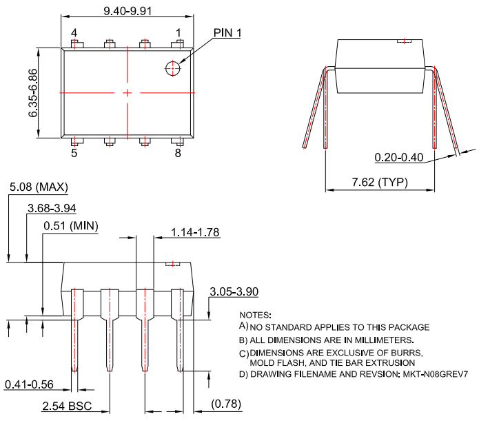
Package
6N138 Manufacturer
ON Semiconductor (Nasdaq: ON) is a disruptive technology firm that is helping to build a brighter future. It was founded in 1999. With an emphasis on automotive and industrial end-markets, the firm is speeding change in megatrends like as vehicle electrification and safety, sustainable energy grids, industrial automation, and 5G and cloud infrastructure. Through a highly specialized and unique product range, Onsemi provides intelligent power and sensor solutions that address the world's most pressing concerns and pave the path for a safer, cleaner, and smarter world.
For automotive, communications, computer, consumer, industrial, LED lighting, medical, military/aerospace, and power applications, products include power and signal management, logic, discrete, and bespoke devices.
Datasheet PDF
- Datasheets :
- Environmental Information :
- PCN Design/Specification :
- PCN Packaging :
 IRF840 N-Channel Power MOSFET: Pinout, Alternative, Test Circuit
03 August 202111071
 IL511 Digital Isolators: Datasheet, Pinout and Applications
28 August 2021389
![CR1216 Battery: What Battery Can Replace CR1216? [FAQ]](https://res.utmel.com/Images/Article/64d95785-90b8-4feb-91f6-240b0cd4cfa7.jpg) CR1216 Battery: What Battery Can Replace CR1216? [FAQ]
CR1216 Battery: What Battery Can Replace CR1216? [FAQ]01 August 202234069
 A Comprehensive Guide to LTC6943IGN#PBF PMIC Voltage Regulator
06 March 2024192
 RS-1205S Regulated Converter: Pinout, Features, Circuit
26 July 20211413
 A Deep Dive into LTC6909CMS#TRPBF Programmable Timer and Oscillator
06 March 2024286
 Renesas DF2317VTF25V Microcontroller: A Technical Overview
29 February 2024110
 LM318 OP-AMP: Datasheet, Pinout, Alternatives and Circuit
09 September 20215856
 Role of Direct Memory Access in Modern Computing
12 November 20243203
 Hybrid Sources Powered Electric Vehicles - Part 2
20 March 20232621
 How does an Inverter Work?
06 April 20218183
 What is RF Switch?
16 November 20215310
 How do Transistors Work?
10 August 202012926
 Network Interface Card: Types, Functions and Buying Guide
17 August 20218245
 Structure and Working Principle of Field Effect Transistors
07 April 202535729
 What is FIR Filter?
24 September 202015623
ON Semiconductor
In Stock: 50
Minimum: 1 Multiples: 1
Qty
Unit Price
Ext Price
1
$0.763045
$0.76
10
$0.719854
$7.20
100
$0.679108
$67.91
500
$0.640668
$320.33
1000
$0.604403
$604.40
Not the price you want? Send RFQ Now and we'll contact you ASAP.
Inquire for More Quantity


