
 Product
 Brand
Brand Articles
 Tools
Tools
A Comprehensive Guide to LTC6421IUDC-20#TRPBF ADC Driver

Linear Technology/Analog Devices
0.5mm 3V 20 Amplifier LTC6421 3V 20-WFQFN Exposed Pad
Unit Price: $38.046094
Ext Price: $38.05


0.5mm 3V 20 Amplifier LTC6421 3V 20-WFQFN Exposed Pad
This technical article provides an in-depth analysis of the LTC6421IUDC-20#TRPBF ADC Driver, manufactured by Linear Technology/Analog Devices. It covers the product description, features, applications, reference designs, alternative parts, and frequently asked questions to help electronic engineers understand and utilize this specialized amplifier effectively.
Product Introduction
1. Description:
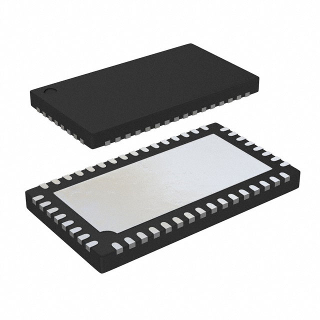
The LTC6421IUDC-20#TRPBF is an ADC Driver specifically designed for data acquisition applications. It is a dual-channel amplifier with a supply voltage of 3V and a maximum supply current of 50mA. The amplifier comes in a compact 20-WFQFN package with an exposed pad for surface mounting. With a wide operating temperature range of -40°C to 85°C and a slew rate of 4500 V/μs, this ADC driver is suitable for industrial applications requiring high-speed and precision signal processing.
2. Features:
- Dual-channel ADC Driver
- Supply Voltage: 3V
- Maximum Supply Current: 50mA
- Slew Rate: 4500 V/μs
- Common Mode Rejection Ratio: 68 dB
- Supply Voltage Limit: 3.6V
- Compact 20-WFQFN Package with Exposed Pad
- Wide Operating Temperature Range: -40°C to 85°C
3. Applications:
Primary Applications:
- Data Acquisition Systems
- Industrial Automation
- Signal Processing Equipment
Secondary Applications:
- Instrumentation Amplifiers
- Medical Devices
- Communication Systems
Applicable Specific Modules:
- High-speed ADC Interfaces
- Sensor Signal Conditioning Circuits
- Precision Measurement Equipment
4. Reference Designs:
The LTC6421IUDC-20#TRPBF ADC Driver is commonly used in the following reference designs:
- High-Speed Data Acquisition System
- Precision Instrumentation Amplifier
- Industrial Control System
5. Alternative Parts:
For engineers looking for alternative options to the LTC6421IUDC-20#TRPBF ADC Driver, the following parts can be considered:
- AD8138
- THS4521
- MAX9632
6. FAQs:
Q: What is the maximum supply voltage supported by the LTC6421IUDC-20#TRPBF ADC Driver?
A: The maximum supply voltage for this ADC Driver is 3.6V.
Q: What is the operating temperature range of the LTC6421IUDC-20#TRPBF ADC Driver?
A: The operating temperature range is -40°C to 85°C, making it suitable for industrial applications.
Q: Can the LTC6421IUDC-20#TRPBF ADC Driver be used in medical devices?
A: Yes, the ADC Driver can be used in medical devices requiring high-speed and precision signal processing.
In conclusion, the LTC6421IUDC-20#TRPBF ADC Driver is a versatile and high-performance amplifier suitable for a wide range of data acquisition and signal processing applications. With its compact design, wide operating temperature range, and dual-channel functionality, it is a reliable choice for engineers working on precision measurement and control systems.
Specifications
- TypeParameter
- Factory Lead Time12 Weeks
- Mounting Type
The "Mounting Type" in electronic components refers to the method used to attach or connect a component to a circuit board or other substrate, such as through-hole, surface-mount, or panel mount.
Surface Mount - Package / Case
refers to the protective housing that encases an electronic component, providing mechanical support, electrical connections, and thermal management.
20-WFQFN Exposed Pad - Surface Mount
having leads that are designed to be soldered on the side of a circuit board that the body of the component is mounted on.
YES - Operating Temperature (Max.)85°C
- Operating Temperature (Min.)-40°C
- Packaging
Semiconductor package is a carrier / shell used to contain and cover one or more semiconductor components or integrated circuits. The material of the shell can be metal, plastic, glass or ceramic.
Tape & Reel (TR) - Published2010
- JESD-609 Code
The "JESD-609 Code" in electronic components refers to a standardized marking code that indicates the lead-free solder composition and finish of electronic components for compliance with environmental regulations.
e3 - Part Status
Parts can have many statuses as they progress through the configuration, analysis, review, and approval stages.
Active - Moisture Sensitivity Level (MSL)
Moisture Sensitivity Level (MSL) is a standardized rating that indicates the susceptibility of electronic components, particularly semiconductors, to moisture-induced damage during storage and the soldering process, defining the allowable exposure time to ambient conditions before they require special handling or baking to prevent failures
1 (Unlimited) - Number of Terminations20
- ECCN Code
An ECCN (Export Control Classification Number) is an alphanumeric code used by the U.S. Bureau of Industry and Security to identify and categorize electronic components and other dual-use items that may require an export license based on their technical characteristics and potential for military use.
EAR99 - TypeADC Driver
- Terminal Finish
Terminal Finish refers to the surface treatment applied to the terminals or leads of electronic components to enhance their performance and longevity. It can improve solderability, corrosion resistance, and overall reliability of the connection in electronic assemblies. Common finishes include nickel, gold, and tin, each possessing distinct properties suitable for various applications. The choice of terminal finish can significantly impact the durability and effectiveness of electronic devices.
Matte Tin (Sn) - Applications
The parameter "Applications" in electronic components refers to the specific uses or functions for which a component is designed. It encompasses various fields such as consumer electronics, industrial automation, telecommunications, automotive, and medical devices. Understanding the applications helps in selecting the right components for a particular design based on performance, reliability, and compatibility requirements. This parameter also guides manufacturers in targeting their products to relevant markets and customer needs.
Data Acquisition - HTS Code
HTS (Harmonized Tariff Schedule) codes are product classification codes between 8-1 digits. The first six digits are an HS code, and the countries of import assign the subsequent digits to provide additional classification. U.S. HTS codes are 1 digits and are administered by the U.S. International Trade Commission.
8542.33.00.01 - Terminal Position
In electronic components, the term "Terminal Position" refers to the physical location of the connection points on the component where external electrical connections can be made. These connection points, known as terminals, are typically used to attach wires, leads, or other components to the main body of the electronic component. The terminal position is important for ensuring proper connectivity and functionality of the component within a circuit. It is often specified in technical datasheets or component specifications to help designers and engineers understand how to properly integrate the component into their circuit designs.
QUAD - Terminal Form
Occurring at or forming the end of a series, succession, or the like; closing; concluding.
NO LEAD - Peak Reflow Temperature (Cel)
Peak Reflow Temperature (Cel) is a parameter that specifies the maximum temperature at which an electronic component can be exposed during the reflow soldering process. Reflow soldering is a common method used to attach electronic components to a circuit board. The Peak Reflow Temperature is crucial because it ensures that the component is not damaged or degraded during the soldering process. Exceeding the specified Peak Reflow Temperature can lead to issues such as component failure, reduced performance, or even permanent damage to the component. It is important for manufacturers and assemblers to adhere to the recommended Peak Reflow Temperature to ensure the reliability and functionality of the electronic components.
260 - Number of Functions2
- Supply Voltage
Supply voltage refers to the electrical potential difference provided to an electronic component or circuit. It is crucial for the proper operation of devices, as it powers their functions and determines performance characteristics. The supply voltage must be within specified limits to ensure reliability and prevent damage to components. Different electronic devices have specific supply voltage requirements, which can vary widely depending on their design and intended application.
3V - Terminal Pitch
The center distance from one pole to the next.
0.5mm - Time@Peak Reflow Temperature-Max (s)
Time@Peak Reflow Temperature-Max (s) refers to the maximum duration that an electronic component can be exposed to the peak reflow temperature during the soldering process, which is crucial for ensuring reliable solder joint formation without damaging the component.
30 - Base Part Number
The "Base Part Number" (BPN) in electronic components serves a similar purpose to the "Base Product Number." It refers to the primary identifier for a component that captures the essential characteristics shared by a group of similar components. The BPN provides a fundamental way to reference a family or series of components without specifying all the variations and specific details.
LTC6421 - Pin Count
a count of all of the component leads (or pins)
20 - JESD-30 Code
JESD-30 Code refers to a standardized descriptive designation system established by JEDEC for semiconductor-device packages. This system provides a systematic method for generating designators that convey essential information about the package's physical characteristics, such as size and shape, which aids in component identification and selection. By using JESD-30 codes, manufacturers and engineers can ensure consistency and clarity in the specification of semiconductor packages across various applications and industries.
R-PQCC-N20 - Qualification Status
An indicator of formal certification of qualifications.
Not Qualified - Power Supplies
an electronic circuit that converts the voltage of an alternating current (AC) into a direct current (DC) voltage.?
3V - Temperature Grade
Temperature grades represent a tire's resistance to heat and its ability to dissipate heat when tested under controlled laboratory test conditions.
INDUSTRIAL - Supply Current-Max
Supply Current-Max refers to the maximum amount of current that an electronic component or circuit can draw from its power supply under specified operating conditions. It is a critical parameter that determines the power consumption and thermal performance of the device. Exceeding this limit can lead to overheating, potential damage, or failure of the component. Knowing the Supply Current-Max helps in designing circuits that ensure proper operation and reliability.
50mA - Slew Rate
the maximum rate of output voltage change per unit time.
4500 V/us - Common Mode Rejection Ratio
Common Mode Rejection Ratio (CMRR) is a measure of the ability of a differential amplifier to reject input signals that are common to both input terminals. It is defined as the ratio of the differential gain to the common mode gain. A high CMRR indicates that the amplifier can effectively eliminate noise and interference that affects both inputs simultaneously, enhancing the fidelity of the amplified signal. CMRR is typically expressed in decibels (dB), with higher values representing better performance in rejecting common mode signals.
68 dB - Supply Voltage Limit-Max
The parameter "Supply Voltage Limit-Max" in electronic components refers to the maximum voltage that the component can safely handle without getting damaged. This specification is crucial for ensuring the reliable operation and longevity of the component within a given electrical system. Exceeding the maximum supply voltage limit can lead to overheating, electrical breakdown, or permanent damage to the component. It is important to carefully adhere to this limit when designing and operating electronic circuits to prevent potential failures and ensure the overall system's performance and safety.
3.6V - Input Offset Voltage-Max
The parameter "Input Offset Voltage-Max" in electronic components refers to the maximum allowable difference in voltage between the input terminals of an operational amplifier or other analog circuitry before the output is affected. It is a measure of the device's ability to maintain precise and accurate signal processing. A higher Input Offset Voltage-Max value indicates a greater potential for error in the output signal due to input voltage differences. Designers must consider this parameter when selecting components to ensure the desired level of accuracy and performance in their circuits.
2000μV - Length4mm
- Height Seated (Max)
Height Seated (Max) is a parameter in electronic components that refers to the maximum allowable height of the component when it is properly seated or installed on a circuit board or within an enclosure. This specification is crucial for ensuring proper fit and alignment within the overall system design. Exceeding the maximum seated height can lead to mechanical interference, electrical shorts, or other issues that may impact the performance and reliability of the electronic device. Manufacturers provide this information to help designers and engineers select components that will fit within the designated space and function correctly in the intended application.
0.8mm - Width3mm
- RoHS Status
RoHS means “Restriction of Certain Hazardous Substances” in the “Hazardous Substances Directive” in electrical and electronic equipment.
ROHS3 Compliant
Parts with Similar Specs
Datasheet PDF
- Datasheets :
 MCP4822 Digital-to-Analog Converter: Datasheet, Pinout and MCP4822 Arduino
25 November 20215640
 Unveiling the SANYO LC87F5R96B 8-Bit Microcontroller: An In-depth Exploration
29 February 2024149
 MPSA05 NPN Transistor: Datasheet, Test Circuit and Equivalent
09 November 20213955
 LTC6950IUHH#TRPBF Clock Generator: A Comprehensive Overview
06 March 2024260
 INA219AIDCNR Amplifier: Pinout, Datasheet, INA219
10 March 20223248
 AT24C16C I²C-Compatible Serial EEPROM: Pinout, Equivalent and Datasheet
07 March 2022605
 1N5404 Rectifier : Pinout, Price, Datasheet
25 August 20211886
 IRFP460A Power MOSFET: Datasheet, Equivalents, Application
11 October 20217063
 Elon Musk: The Neuralink Brain Chip Developed By Its Company Could Help Treat Morbid Obesity
24 April 20222604
 SEMI: Semiconductor Materials Market to Exceed US$70 Billion By 2023
27 September 20222660
 2026 Passive Components Market Update: Sourcing Tactics Amid Price Hikes and Lead Time Extensions
15 June 20261781
 What is a Fixed Inductor?
15 April 202113180
 What is Instrument Transformer?
08 January 20227714
 Basic Introduction to System on a Chip
02 December 20204626
 A Guide to the Best AG13 Battery Substitutes
27 May 20252633
 The Introduction of Car Fuse
09 October 20216652
Linear Technology/Analog Devices
In Stock: 1000
Minimum: 1 Multiples: 1
Qty
Unit Price
Ext Price
1
$38.046094
$38.05
10
$35.892542
$358.93
100
$33.860888
$3,386.09
500
$31.944234
$15,972.12
1000
$30.136070
$30,136.07
Not the price you want? Send RFQ Now and we'll contact you ASAP.
Inquire for More Quantity
![AD8138ARZ]() AD8138ARZ
AD8138ARZAnalog Devices Inc.
![AD8138ARMZ]() AD8138ARMZ
AD8138ARMZAnalog Devices Inc.
![AD8310ARMZ]() AD8310ARMZ
AD8310ARMZAnalog Devices Inc.
![ADA4941-1YRZ]() ADA4941-1YRZ
ADA4941-1YRZAnalog Devices Inc.
![AD8309ARUZ]() AD8309ARUZ
AD8309ARUZAnalog Devices Inc.
![AD8331ARQZ]() AD8331ARQZ
AD8331ARQZAnalog Devices Inc.
![AD8138ARZ-R7]() AD8138ARZ-R7
AD8138ARZ-R7Analog Devices Inc.
![AD8138ARMZ-REEL7]() AD8138ARMZ-REEL7
AD8138ARMZ-REEL7Analog Devices Inc.
![AD8310ARMZ-REEL7]() AD8310ARMZ-REEL7
AD8310ARMZ-REEL7Analog Devices Inc.
![AD8307ARZ]() AD8307ARZ
AD8307ARZAnalog Devices Inc.


