
 Product
 Brand
Brand Articles
 Tools
Tools
A1266 3D Hall-Effect Switch: Datasheet, Equivalent and Pinout

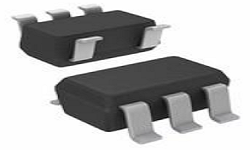
Open Drain 2.5V~5.5V -40°C~85°C TA Omnipolar Switch North Pole, South Pole ±4mT Trip, ±0.5mT Release SOT-23-5 Thin, TSOT-23-5
Unit Price: $0.737381
Ext Price: $0.74


Open Drain 2.5V~5.5V -40°C~85°C TA Omnipolar Switch North Pole, South Pole ±4mT Trip, ±0.5mT Release SOT-23-5 Thin, TSOT-23-5
A1266 is a Micropower Ultrasensitive 3D Hall-Effect Switch. This article mainly covers equivalent, power, datasheet, pinout, and other details about A1266. Furthermore, there is a huge range of semiconductors, capacitors, resistors, and ICs in stock. Welcome your RFQ!

How to use Hall Effect Switches
What is A1266?
The A1266 integrated circuit is an ultrasensitive Hall-effect switch with 3D omnipolar magnetic actuation. When a magnetic field of sufficient strength is applied to the sensor in either orientation, the device outputs switch on. The output will be turned off if the magnetic field is removed.
A1266 Pinout

A1266 Pinout
| Pin Number | Symbol | Description |
| 1 | VDD | Power Supply |
| 2 | OUT | X+Y+Z Output |
| 3 | NC | No connection |
| 4 | GND | Ground |
| 5 | NC | No connection |
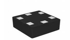
A1266 CAD Model
Footprint

A1266 Footprint
A1266 Functional Block Diagram

A1266 Functional Block Diagram
Specifications
- TypeParameter
- Factory Lead Time8 Weeks
- Mounting Type
The "Mounting Type" in electronic components refers to the method used to attach or connect a component to a circuit board or other substrate, such as through-hole, surface-mount, or panel mount.
Surface Mount - Package / Case
refers to the protective housing that encases an electronic component, providing mechanical support, electrical connections, and thermal management.
SOT-23-5 Thin, TSOT-23-5 - Surface Mount
having leads that are designed to be soldered on the side of a circuit board that the body of the component is mounted on.
YES - Test Conditions-40°C ~ 85°C
- Operating Temperature
The operating temperature is the range of ambient temperature within which a power supply, or any other electrical equipment, operate in. This ranges from a minimum operating temperature, to a peak or maximum operating temperature, outside which, the power supply may fail.
-40°C~85°C TA - Packaging
Semiconductor package is a carrier / shell used to contain and cover one or more semiconductor components or integrated circuits. The material of the shell can be metal, plastic, glass or ceramic.
Tape & Reel (TR) - Published2015
- Part Status
Parts can have many statuses as they progress through the configuration, analysis, review, and approval stages.
Active - Moisture Sensitivity Level (MSL)
Moisture Sensitivity Level (MSL) is a standardized rating that indicates the susceptibility of electronic components, particularly semiconductors, to moisture-induced damage during storage and the soldering process, defining the allowable exposure time to ambient conditions before they require special handling or baking to prevent failures
1 (Unlimited) - Number of Terminations5
- HTS Code
HTS (Harmonized Tariff Schedule) codes are product classification codes between 8-1 digits. The first six digits are an HS code, and the countries of import assign the subsequent digits to provide additional classification. U.S. HTS codes are 1 digits and are administered by the U.S. International Trade Commission.
8542.39.00.01 - Voltage - Supply
Voltage - Supply refers to the range of voltage levels that an electronic component or circuit is designed to operate with. It indicates the minimum and maximum supply voltage that can be applied for the device to function properly. Providing supply voltages outside this range can lead to malfunction, damage, or reduced performance. This parameter is critical for ensuring compatibility between different components in a circuit.
2.5V~5.5V - Terminal Position
In electronic components, the term "Terminal Position" refers to the physical location of the connection points on the component where external electrical connections can be made. These connection points, known as terminals, are typically used to attach wires, leads, or other components to the main body of the electronic component. The terminal position is important for ensuring proper connectivity and functionality of the component within a circuit. It is often specified in technical datasheets or component specifications to help designers and engineers understand how to properly integrate the component into their circuit designs.
DUAL - Terminal Form
Occurring at or forming the end of a series, succession, or the like; closing; concluding.
GULL WING - Peak Reflow Temperature (Cel)
Peak Reflow Temperature (Cel) is a parameter that specifies the maximum temperature at which an electronic component can be exposed during the reflow soldering process. Reflow soldering is a common method used to attach electronic components to a circuit board. The Peak Reflow Temperature is crucial because it ensures that the component is not damaged or degraded during the soldering process. Exceeding the specified Peak Reflow Temperature can lead to issues such as component failure, reduced performance, or even permanent damage to the component. It is important for manufacturers and assemblers to adhere to the recommended Peak Reflow Temperature to ensure the reliability and functionality of the electronic components.
NOT SPECIFIED - Supply Voltage
Supply voltage refers to the electrical potential difference provided to an electronic component or circuit. It is crucial for the proper operation of devices, as it powers their functions and determines performance characteristics. The supply voltage must be within specified limits to ensure reliability and prevent damage to components. Different electronic devices have specific supply voltage requirements, which can vary widely depending on their design and intended application.
3.3V - Terminal Pitch
The center distance from one pole to the next.
0.95mm - Time@Peak Reflow Temperature-Max (s)
Time@Peak Reflow Temperature-Max (s) refers to the maximum duration that an electronic component can be exposed to the peak reflow temperature during the soldering process, which is crucial for ensuring reliable solder joint formation without damaging the component.
NOT SPECIFIED - JESD-30 Code
JESD-30 Code refers to a standardized descriptive designation system established by JEDEC for semiconductor-device packages. This system provides a systematic method for generating designators that convey essential information about the package's physical characteristics, such as size and shape, which aids in component identification and selection. By using JESD-30 codes, manufacturers and engineers can ensure consistency and clarity in the specification of semiconductor packages across various applications and industries.
R-PDSO-G5 - Function
The parameter "Function" in electronic components refers to the specific role or purpose that the component serves within an electronic circuit. It defines how the component interacts with other elements, influences the flow of electrical signals, and contributes to the overall behavior of the system. Functions can include amplification, signal processing, switching, filtering, and energy storage, among others. Understanding the function of each component is essential for designing effective and efficient electronic systems.
Omnipolar Switch - Output Type
The "Output Type" parameter in electronic components refers to the type of signal or data that is produced by the component as an output. This parameter specifies the nature of the output signal, such as analog or digital, and can also include details about the voltage levels, current levels, frequency, and other characteristics of the output signal. Understanding the output type of a component is crucial for ensuring compatibility with other components in a circuit or system, as well as for determining how the output signal can be utilized or processed further. In summary, the output type parameter provides essential information about the nature of the signal that is generated by the electronic component as its output.
Open Drain - Max Output Current
The maximum current that can be supplied to the load.
3mA - Supply Voltage-Max (Vsup)
The parameter "Supply Voltage-Max (Vsup)" in electronic components refers to the maximum voltage that can be safely applied to the component without causing damage. It is an important specification to consider when designing or using electronic circuits to ensure the component operates within its safe operating limits. Exceeding the maximum supply voltage can lead to overheating, component failure, or even permanent damage. It is crucial to adhere to the specified maximum supply voltage to ensure the reliable and safe operation of the electronic component.
5.5V - Supply Voltage-Min (Vsup)
The parameter "Supply Voltage-Min (Vsup)" in electronic components refers to the minimum voltage level required for the component to operate within its specified performance range. This parameter indicates the lowest voltage that can be safely applied to the component without risking damage or malfunction. It is crucial to ensure that the supply voltage provided to the component meets or exceeds this minimum value to ensure proper functionality and reliability. Failure to adhere to the specified minimum supply voltage may result in erratic behavior, reduced performance, or even permanent damage to the component.
2.5V - Analog IC - Other Type
Analog IC - Other Type is a parameter used to categorize electronic components that are integrated circuits (ICs) designed for analog signal processing but do not fall into more specific subcategories such as amplifiers, comparators, or voltage regulators. These ICs may include specialized analog functions such as analog-to-digital converters (ADCs), digital-to-analog converters (DACs), voltage references, or signal conditioning circuits. They are typically used in various applications where precise analog signal processing is required, such as in audio equipment, instrumentation, communication systems, and industrial control systems. Manufacturers provide detailed specifications for these components to help engineers select the most suitable IC for their specific design requirements.
ANALOG CIRCUIT - Polarization
In electronic components, polarization refers to the orientation or alignment of certain properties within the component. This property can affect the behavior and performance of the component in a circuit. For example, in capacitors, polarization refers to the alignment of the electric field within the dielectric material. Polarized capacitors, such as electrolytic capacitors, have a specific orientation for proper functioning. In other components like diodes, polarization refers to the direction of current flow, which is important for their correct operation. Understanding polarization is crucial for proper usage and integration of electronic components in circuits.
North Pole, South Pole - Max Supply Current
Max Supply Current refers to the maximum amount of electrical current that a component can draw from its power supply under normal operating conditions. It is a critical parameter that ensures the component operates reliably without exceeding its thermal limits or damaging internal circuitry. Exceeding this current can lead to overheating, performance degradation, or failure of the component. Understanding this parameter is essential for designing circuits that provide adequate power while avoiding overload situations.
3mA - Sensing Method
The sensing method in electronic components refers to the technique or mechanism used to detect and measure physical phenomena such as temperature, pressure, light, or motion. This includes a variety of technologies such as resistive, capacitive, inductive, and optical sensing methods. The choice of sensing method affects the accuracy, response time, and application suitability of the electronic component. It plays a crucial role in determining how effectively a device can interact with and interpret its environment.
Hall Effect - Sensing Range
The sensing range of position sensors is the displacement between the sensing face of the sensor and the approaching measurement object that triggers a signal change in the sensor.
±4mT Trip, ±0.5mT Release - Length2.98mm
- Height Seated (Max)
Height Seated (Max) is a parameter in electronic components that refers to the maximum allowable height of the component when it is properly seated or installed on a circuit board or within an enclosure. This specification is crucial for ensuring proper fit and alignment within the overall system design. Exceeding the maximum seated height can lead to mechanical interference, electrical shorts, or other issues that may impact the performance and reliability of the electronic device. Manufacturers provide this information to help designers and engineers select components that will fit within the designated space and function correctly in the intended application.
1.13mm - Width1.91mm
- RoHS Status
RoHS means “Restriction of Certain Hazardous Substances” in the “Hazardous Substances Directive” in electrical and electronic equipment.
ROHS3 Compliant
A1266 Features
True 3D sensing
Omnipolar operation with either north or South Pole
2.5 to 5.5 V operations
Low supply current
High sensitivity, BOP typically 25 G
Chopper-stabilized offset cancellation
Superior temperature stability
Extremely low switch point drift
Insensitive to physical stress
Solid-state reliability
Choice of output format
Separate X, Y, and Z outputs
Combined (X+Y+Z) output
Tiny SOT-23 packages
A1266 Applications
Current Transformers
Position Sensing
Keyboard Switch
Computers
Proximity Sensing
Speed Detection
Current Sensing Applications
Tachometers
Anti-Lock Braking Systems
Magnetometers
DC motors
Disk Drives
A1266 Typical Application Circuit
One pin reports the output state from any of the three Hall components for sensors configured with the single output option.

Typical Application Circuit for the Single Output Selection
The three distinct open-drain outputs from the respective Hall elements report the output state for sensors configured with the triple output option.

Typical Application Circuit for the Triple Output Selection
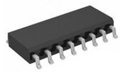
A1266 Package

A1266 Package
A1266 Manufacturer
As a leading company in the development, manufacture, and market of high-performance semiconductors, Allegro MicroSystems, LLC provides high-growth applications for the automotive market and also stays focused on consumer/communications, automation, and industrial solutions. Headquartered in Worcester, Massachusetts (USA) Allegro locates its design, applications, and sales support centers worldwide.
Trend Analysis
Datasheet PDF
- Datasheets :
What is the A1266 used for?
The A1266 can be used also to measure the density of current carriers, their freedom of movement, or mobility, as well as to detect the presence of a current on a magnetic field.
How does A1266 Hall Effect switch work?
A1266 Hall Effect switch turns on in the presence of a magnetic field and turns off when the magnet is removed. A Hall Effect latch turns on (closes) when a positive magnetic field is applied and remains on even when the magnet is removed.
How do you check Hall Effect switch?
Place a magnet near the Hall Effect switch. If the LED lights up and responds to the magnet, then you have a working switch. Note: If the battery is low, and is supplying less than 5 V DC, the Hall Effect switch will stay “ON” all the time or won't work at all.
 LM3900 Norton Op Amp: Circuit, Pinout, and Datasheet
22 April 20224509
 2N3866 Transistor: Datasheet, Equivalent, Pinout
15 November 20216652
 HTS221 Sensor: Datasheet, Pinout and Block Diagram
27 October 20211928
 AD9910 Digital Synthesizer: Datasheet, Schematic and Pinout
26 July 20215019
 SG3525AP IC: Schematic, Applications and Datasheet
03 November 20232301
 SN74LV1T34DBVR Shifter: Pinout, Applications and Datasheet
09 December 20231376
 OPA2134 VS NE5532 How to differentiate the OPA2134 and NE5532
25 March 202213135
 IRF620 N-Channel Power MOSFET: Datasheet pdf, 6A 200V MOSFET and Pinout
24 December 20212829
 FPGA in Industry and Communication: Key Players, Technologies, and Future Trends
07 March 20251967
 MOSFET vs. IGBT: Characteristics, Structure and Market Analysis
25 December 202520788
 What is a Semiconductor?
22 October 20257489
 Hybrid Sources Powered Electric Vehicles - Part 1
08 March 20233309
 What is Low Pass Filter
18 November 20216651
 Google Acquires MicroLED Display Company Raxium, May Boost Its AR Headset
09 May 20221863
 Application of Wide Bandgap Devices in EV Converters
12 April 20231222
 SMD Resistors: Codes, Size, Testing, Tolerance and Selection
23 October 202548006
Allegro MicroSystems
In Stock: 1742
Minimum: 1 Multiples: 1
Qty
Unit Price
Ext Price
1
$0.737381
$0.74
10
$0.695642
$6.96
100
$0.656266
$65.63
500
$0.619119
$309.56
1000
$0.584075
$584.08
Not the price you want? Send RFQ Now and we'll contact you ASAP.
Inquire for More Quantity
![A1180LUA-T]() A1180LUA-T
A1180LUA-TAllegro MicroSystems
![A1106LUA-T]() A1106LUA-T
A1106LUA-TAllegro MicroSystems
![A1104EUA-T]() A1104EUA-T
A1104EUA-TAllegro MicroSystems
![A3213ELHLT-T]() A3213ELHLT-T
A3213ELHLT-TAllegro MicroSystems
![A3214ELHLT-T]() A3214ELHLT-T
A3214ELHLT-TAllegro MicroSystems
![A1120ELHLT-T]() A1120ELHLT-T
A1120ELHLT-TAllegro MicroSystems
![A3213EUA-T]() A3213EUA-T
A3213EUA-TAllegro MicroSystems
![A3212EUA-T]() A3212EUA-T
A3212EUA-TAllegro MicroSystems
![A1102ELHLT-T]() A1102ELHLT-T
A1102ELHLT-TAllegro MicroSystems
![A1102EUA-T]() A1102EUA-T
A1102EUA-TAllegro MicroSystems

