
 Product
 Brand
Brand Articles
 Tools
Tools
AD7878BQ Converter:Pinout, Specification, Datasheet

12 Bit 2.54mm Lead, Tin ADC AD7878 5V 28-CDIP (0.600, 15.24mm)
Unit Price: $148.199628
Ext Price: $148.20


12 Bit 2.54mm Lead, Tin ADC AD7878 5V 28-CDIP (0.600, 15.24mm)
The AD7878BQ is a fast, complete, 12-bit A/D converter with a versatile DSP interface consisting of an 8-word, first-in, first-out (FIFO) memory and associated control logic.
AD7878BQ Pinout


AD7878BQ Description
The FIFO memory allows up to eight samples to be digitized before the microprocessor is required to service the A/D converter. The eight words can then be read out of the FIFO at maximum microprocessor speed. A fast data access time of 41 ns allows direct interfacing to DSP processors and high-speed 16-bit microprocessors.
An on-chip status/control register allows the user to program the effective length of the FIFO and contains the FIFO out of range, FIFO empty, and FIFO word count information.
The analog input of the AD7878 has a bipolar range of ±3 V. The AD7878 can convert full power signals up to 50 kHz and is fully specified for dynamic parameters such as signal-to-noise ratio and harmonic distortion.
The AD7878 is fabricated in Linear Compatible CMOS (LC2 MOS), an advanced, mixed technology process that combines precision bipolar circuits with low power CMOS logic. The part is available in four package styles, 28-pin plastic and hermetic dual-in-line package (DIP), leadless ceramic chip carrier (LCCC), or plastic leaded chip carrier (PLCC).
AD7878BQ Features
Complete ADC with DSP Interface, Comprising: Track/Hold Amplifier with 2 ms Acquisition Time; 7 ms A/D Converter; 3 V Zener Reference; 8-Word FIFO and Interface Logic
72 dB SNR at 10 kHz Input Frequency
Interfaces to High-Speed DSP Processors, e.g., ADSP-2100, TMS32010, TMS32020
41 ns max Data Access Time
Low Power, 60 mW typ
AD7878BQ Advantages
Complete A/D Function with DSP Interface
The AD7878 provides the complete function for digitizing ac signals to 12-bit accuracy. The part features an on-chip track/hold, on-chip reference, and 12-bit A/D converter. The additional feature of an 8-word FIFO reduces the high software overheads associated with servicing interrupts in DSP processors.
Dynamic Specifications for DSP Users
The AD7878 is fully specified and tested for ac parameters, including signal-to-noise ratio, harmonic distortion and intermodulation distortion. Key digital timing parameters are also tested and specified over the full operating temperature range.
Fast Microprocessor Interface
The data access time of 41 ns is the fastest ever achieved in a monolithic A/D converter, and makes the AD7878 compatible with all modern 16-bit microprocessors and digital signal processors.
AD7878BQ Applications
Digital Signal Processing
Speech Recognition and Synthesis
Spectrum Analysis
High-Speed Modems
DSP Servo Control
Specifications
- TypeParameter
- Lifecycle Status
Lifecycle Status refers to the current stage of an electronic component in its product life cycle, indicating whether it is active, obsolete, or transitioning between these states. An active status means the component is in production and available for purchase. An obsolete status indicates that the component is no longer being manufactured or supported, and manufacturers typically provide a limited time frame for support. Understanding the lifecycle status is crucial for design engineers to ensure continuity and reliability in their projects.
PRODUCTION (Last Updated: 5 days ago) - Factory Lead Time8 Weeks
- Contact Plating
Contact plating (finish) provides corrosion protection for base metals and optimizes the mechanical and electrical properties of the contact interfaces.
Lead, Tin - Mount
In electronic components, the term "Mount" typically refers to the method or process of physically attaching or fixing a component onto a circuit board or other electronic device. This can involve soldering, adhesive bonding, or other techniques to secure the component in place. The mounting process is crucial for ensuring proper electrical connections and mechanical stability within the electronic system. Different components may have specific mounting requirements based on their size, shape, and function, and manufacturers provide guidelines for proper mounting procedures to ensure optimal performance and reliability of the electronic device.
Through Hole - Mounting Type
The "Mounting Type" in electronic components refers to the method used to attach or connect a component to a circuit board or other substrate, such as through-hole, surface-mount, or panel mount.
Through Hole - Package / Case
refers to the protective housing that encases an electronic component, providing mechanical support, electrical connections, and thermal management.
28-CDIP (0.600, 15.24mm) - Number of Pins28
- Operating Temperature
The operating temperature is the range of ambient temperature within which a power supply, or any other electrical equipment, operate in. This ranges from a minimum operating temperature, to a peak or maximum operating temperature, outside which, the power supply may fail.
-25°C~85°C - Packaging
Semiconductor package is a carrier / shell used to contain and cover one or more semiconductor components or integrated circuits. The material of the shell can be metal, plastic, glass or ceramic.
Tube - JESD-609 Code
The "JESD-609 Code" in electronic components refers to a standardized marking code that indicates the lead-free solder composition and finish of electronic components for compliance with environmental regulations.
e0 - Pbfree Code
The "Pbfree Code" parameter in electronic components refers to the code or marking used to indicate that the component is lead-free. Lead (Pb) is a toxic substance that has been widely used in electronic components for many years, but due to environmental concerns, there has been a shift towards lead-free alternatives. The Pbfree Code helps manufacturers and users easily identify components that do not contain lead, ensuring compliance with regulations and promoting environmentally friendly practices. It is important to pay attention to the Pbfree Code when selecting electronic components to ensure they meet the necessary requirements for lead-free applications.
no - Part Status
Parts can have many statuses as they progress through the configuration, analysis, review, and approval stages.
Active - Moisture Sensitivity Level (MSL)
Moisture Sensitivity Level (MSL) is a standardized rating that indicates the susceptibility of electronic components, particularly semiconductors, to moisture-induced damage during storage and the soldering process, defining the allowable exposure time to ambient conditions before they require special handling or baking to prevent failures
1 (Unlimited) - Number of Terminations28
- ECCN Code
An ECCN (Export Control Classification Number) is an alphanumeric code used by the U.S. Bureau of Industry and Security to identify and categorize electronic components and other dual-use items that may require an export license based on their technical characteristics and potential for military use.
EAR99 - Terminal Finish
Terminal Finish refers to the surface treatment applied to the terminals or leads of electronic components to enhance their performance and longevity. It can improve solderability, corrosion resistance, and overall reliability of the connection in electronic assemblies. Common finishes include nickel, gold, and tin, each possessing distinct properties suitable for various applications. The choice of terminal finish can significantly impact the durability and effectiveness of electronic devices.
Tin/Lead (Sn/Pb) - Max Power Dissipation
The maximum power that the MOSFET can dissipate continuously under the specified thermal conditions.
95.5mW - Peak Reflow Temperature (Cel)
Peak Reflow Temperature (Cel) is a parameter that specifies the maximum temperature at which an electronic component can be exposed during the reflow soldering process. Reflow soldering is a common method used to attach electronic components to a circuit board. The Peak Reflow Temperature is crucial because it ensures that the component is not damaged or degraded during the soldering process. Exceeding the specified Peak Reflow Temperature can lead to issues such as component failure, reduced performance, or even permanent damage to the component. It is important for manufacturers and assemblers to adhere to the recommended Peak Reflow Temperature to ensure the reliability and functionality of the electronic components.
NOT APPLICABLE - Number of Functions1
- Supply Voltage
Supply voltage refers to the electrical potential difference provided to an electronic component or circuit. It is crucial for the proper operation of devices, as it powers their functions and determines performance characteristics. The supply voltage must be within specified limits to ensure reliability and prevent damage to components. Different electronic devices have specific supply voltage requirements, which can vary widely depending on their design and intended application.
5V - Terminal Pitch
The center distance from one pole to the next.
2.54mm - Reach Compliance Code
Reach Compliance Code refers to a designation indicating that electronic components meet the requirements set by the Registration, Evaluation, Authorization, and Restriction of Chemicals (REACH) regulation in the European Union. It signifies that the manufacturer has assessed and managed the chemical substances within the components to ensure safety and environmental protection. This code is vital for compliance with regulations aimed at minimizing risks associated with hazardous substances in electronic products.
not_compliant - Time@Peak Reflow Temperature-Max (s)
Time@Peak Reflow Temperature-Max (s) refers to the maximum duration that an electronic component can be exposed to the peak reflow temperature during the soldering process, which is crucial for ensuring reliable solder joint formation without damaging the component.
NOT APPLICABLE - Base Part Number
The "Base Part Number" (BPN) in electronic components serves a similar purpose to the "Base Product Number." It refers to the primary identifier for a component that captures the essential characteristics shared by a group of similar components. The BPN provides a fundamental way to reference a family or series of components without specifying all the variations and specific details.
AD7878 - Pin Count
a count of all of the component leads (or pins)
28 - Qualification Status
An indicator of formal certification of qualifications.
Not Qualified - Polarity
In electronic components, polarity refers to the orientation or direction in which the component must be connected in a circuit to function properly. Components such as diodes, capacitors, and LEDs have polarity markings to indicate which terminal should be connected to the positive or negative side of the circuit. Connecting a component with incorrect polarity can lead to malfunction or damage. It is important to pay attention to polarity markings and follow the manufacturer's instructions to ensure proper operation of electronic components.
Bipolar - Configuration
The parameter "Configuration" in electronic components refers to the specific arrangement or setup of the components within a circuit or system. It encompasses how individual elements are interconnected and their physical layout. Configuration can affect the functionality, performance, and efficiency of the electronic system, and may influence factors such as signal flow, impedance, and power distribution. Understanding the configuration is essential for design, troubleshooting, and optimizing electronic devices.
S/H-ADC - Number of Channels1
- Interface
In electronic components, the term "Interface" refers to the point at which two different systems, devices, or components connect and interact with each other. It can involve physical connections such as ports, connectors, or cables, as well as communication protocols and standards that facilitate the exchange of data or signals between the connected entities. The interface serves as a bridge that enables seamless communication and interoperability between different parts of a system or between different systems altogether. Designing a reliable and efficient interface is crucial in ensuring proper functionality and performance of electronic components and systems.
Parallel - Power Dissipation
the process by which an electronic or electrical device produces heat (energy loss or waste) as an undesirable derivative of its primary action.
60mW - Number of Bits12
- Input Type
Input type in electronic components refers to the classification of the signal or data that a component can accept for processing or conversion. It indicates whether the input is analog, digital, or a specific format such as TTL or CMOS. Understanding input type is crucial for ensuring compatibility between different electronic devices and circuits, as it determines how signals are interpreted and interacted with.
Single Ended - Architecture
In electronic components, the parameter "Architecture" refers to the overall design and structure of the component. It encompasses the arrangement of internal components, the layout of circuitry, and the physical form of the component. The architecture of an electronic component plays a crucial role in determining its functionality, performance, and compatibility with other components in a system. Different architectures can result in variations in power consumption, speed, size, and other key characteristics of the component. Designers often consider the architecture of electronic components carefully to ensure optimal performance and integration within a larger system.
SAR - Converter Type
The parameter "Converter Type" in electronic components refers to the classification of devices that convert one form of energy or signal to another. This includes devices such as analog-to-digital converters (ADCs), digital-to-analog converters (DACs), and various types of signal converters used in communication, power management, and measurement systems. Each converter type is designed to facilitate the manipulation or transformation of signals to meet specific application requirements. The choice of converter type typically depends on factors such as the signal characteristics, required accuracy, and conversion speed.
ADC, PROPRIETARY METHOD - Supply Type
Supply Type in electronic components refers to the classification of power sources used to operate the component. It indicates whether the component requires DC or AC power, and if DC, specifies the voltage levels such as low, medium, or high. Different supply types can affect the performance, compatibility, and application of the component in electronic circuits. Understanding the supply type is crucial for proper component selection and integration into electronic designs.
Dual - Reference Type
a code object that is not stored directly where it is created, but that acts as a kind of pointer to a value stored elsewhere.
Internal - Data Interface
A Data Interface in EDQ is a template of a set of attributes representing a given entity, used to create processes that read from, or write to, interfaces rather than directly from or to sources or targets of data.
DSP - Resolution
Resolution in electronic components refers to the smallest increment of measurement or change that can be detected or represented by the component. It is a crucial specification in devices such as sensors, displays, and converters, as it determines the level of detail or accuracy that can be achieved. For example, in a digital camera, resolution refers to the number of pixels that make up an image, with higher resolution indicating a greater level of detail. In analog-to-digital converters, resolution is the number of discrete values that can be represented in the digital output, determining the precision of the conversion process. Overall, resolution plays a significant role in determining the performance and capabilities of electronic components in various applications.
1.5 B - Sampling Rate
often described in the context of signal processing as the number of samples per time.
100 ksps - Voltage - Supply, Analog
Voltage - Supply, Analog is a parameter in electronic components that specifies the range of voltage levels required to power the analog circuitry within the component. This parameter indicates the minimum and maximum voltage levels that the component can accept for proper operation of its analog functions. It is crucial to ensure that the voltage supplied to the component falls within this specified range to prevent damage and ensure optimal performance. Understanding and adhering to the "Voltage - Supply, Analog" parameter is essential for the proper functioning of analog circuits in electronic components.
±5V - Number of Analog In Channels1
- Sampling Rate (Per Second)
The sampling rate (per second) in electronic components refers to the frequency at which an analog signal is measured or sampled to convert it into a digital signal. It is typically expressed in Hertz (Hz) and indicates how many times per second the analog signal is sampled. A higher sampling rate allows for better representation of the original signal, capturing more detail and reducing distortion during the conversion process. In audio applications, for example, common sampling rates include 44.1 kHz for CD-quality audio and 48 kHz for video production.
100k - Max Dual Supply Voltage
A Dual power supply is a regular direct current power supply. It can provide a positive as well as negative voltage. It ensures stable power supply to the device as well as it helps to prevent system damage.
5.25V - Output Bit Code
Output Bit Code refers to the digital representation of the output signal of an electronic component, typically in binary form. It indicates the specific combination of bits that represent the output value of the component. The output bit code is crucial for interpreting and processing the output data accurately in digital systems. By understanding the output bit code, engineers can design appropriate circuits and algorithms to manipulate and utilize the output information effectively.
BINARY - Integral Nonlinearity (INL)
Integral Nonlinearity (INL) is a measure of the deviation of a transfer function from a straight line when considering the entire output range of a device, such as a digital-to-analog converter or an analog-to-digital converter. It is quantified as the maximum deviation of the actual output from the ideal output across the entire input range, expressed as a percentage of the full-scale output. INL indicates how closely the output follows a linear model, influencing the accuracy of the signal representation in electronic components. A lower INL value signifies better linearity and higher precision in signal processing applications.
0.25 LSB - Min Dual Supply Voltage
The parameter "Min Dual Supply Voltage" in electronic components refers to the minimum voltage required for the proper operation of a device that uses dual power supplies. Dual power supplies typically consist of a positive and a negative voltage source. The "Min Dual Supply Voltage" specification ensures that both the positive and negative supply voltages are within a certain range to guarantee the device functions correctly. It is important to adhere to this parameter to prevent damage to the component and ensure reliable performance.
4.75V - Sample and Hold / Track and Hold
"Sample and Hold" and "Track and Hold" are two related functions commonly found in electronic components such as analog-to-digital converters (ADCs) and signal processing circuits. In a Sample and Hold circuit, the input signal is sampled at specific intervals and held constant until the next sampling period. This allows the circuit to capture and store the input signal's value for further processing or conversion.On the other hand, a Track and Hold circuit continuously tracks the input signal's value and holds it steady when required, typically during the conversion process. This ensures that the input signal remains constant and accurate during the conversion process.Both functions are essential in maintaining the integrity and accuracy of analog signals in digital systems, allowing for precise measurements and processing of signals in various electronic applications.
TRACK - Dual Supply Voltage
Dual Supply Voltage refers to an electronic component's requirement for two separate power supply voltages, typically one positive and one negative. This configuration is commonly used in operational amplifiers, analog circuits, and certain digital devices to allow for greater signal handling capabilities and improved performance. The use of dual supply voltages enables the device to process bipolar signals, thereby enhancing its functionality in various applications.
5V - Ratio - S/H:ADC
The parameter "Ratio - S/H:ADC" in electronic components refers to the ratio between the sample and hold (S/H) circuit and the analog-to-digital converter (ADC) in a system. The sample and hold circuit is responsible for capturing and holding the input signal at a specific moment in time, while the ADC converts this analog signal into a digital format for processing. The ratio between the S/H and ADC components is important as it determines the accuracy and speed of the analog-to-digital conversion process. A higher ratio typically indicates a more precise and efficient conversion process, leading to better overall performance of the electronic system. Engineers often consider this parameter when designing and optimizing electronic circuits to ensure reliable and high-quality signal processing.
1:1 - Analog Input Voltage-Max
Analog Input Voltage-Max refers to the maximum voltage level that can be safely applied to the input of an electronic component, such as an integrated circuit or sensor, without causing damage. This parameter is crucial for ensuring the proper functioning and longevity of the component. Exceeding the specified maximum input voltage can lead to overloading, overheating, or even permanent damage to the component. It is important for designers and engineers to carefully consider and adhere to this parameter when designing circuits or systems to prevent potential failures and ensure reliable operation.
3V - Negative Supply Voltage-Nom
The parameter "Negative Supply Voltage-Nom" in electronic components refers to the nominal voltage level that can be safely applied as the negative supply voltage to the component. This parameter is important for ensuring the proper functioning and reliability of the component within its specified operating conditions. It indicates the voltage level that the component is designed to operate with when a negative voltage supply is required. It is crucial to adhere to this specified voltage range to prevent damage to the component and maintain its performance characteristics.
-5V - Differential Nonlinearity
Differential Nonlinearity (DNL) is a parameter used to measure the deviation of the actual step size between two adjacent digital output codes in an analog-to-digital converter (ADC) or digital-to-analog converter (DAC) from the ideal step size. It quantifies the accuracy of the converter in maintaining consistent step sizes across the entire range of digital codes. DNL is typically expressed in terms of least significant bits (LSBs) and is an important factor in determining the overall performance and linearity of the converter. A lower DNL value indicates better linearity and accuracy in the conversion process, while a higher DNL value suggests potential errors and nonlinearity in the output signal.
0.5 LSB - Analog Input Voltage-Min
Analog Input Voltage-Min refers to the minimum voltage level that an electronic component or device can accept as an input signal in analog form. This parameter is crucial for ensuring proper functionality and performance of the component, as providing a voltage below this minimum level may result in inaccurate readings, errors, or even damage to the device. Designers and engineers need to consider this specification when designing circuits or systems to ensure that the input voltage provided falls within the acceptable range for reliable operation. It is important to adhere to the specified minimum input voltage to prevent any potential issues and maintain the integrity of the electronic component.
-3V - Height Seated (Max)
Height Seated (Max) is a parameter in electronic components that refers to the maximum allowable height of the component when it is properly seated or installed on a circuit board or within an enclosure. This specification is crucial for ensuring proper fit and alignment within the overall system design. Exceeding the maximum seated height can lead to mechanical interference, electrical shorts, or other issues that may impact the performance and reliability of the electronic device. Manufacturers provide this information to help designers and engineers select components that will fit within the designated space and function correctly in the intended application.
5.59mm - RoHS Status
RoHS means “Restriction of Certain Hazardous Substances” in the “Hazardous Substances Directive” in electrical and electronic equipment.
Non-RoHS Compliant - Lead Free
Lead Free is a term used to describe electronic components that do not contain lead as part of their composition. Lead is a toxic material that can have harmful effects on human health and the environment, so the electronics industry has been moving towards lead-free components to reduce these risks. Lead-free components are typically made using alternative materials such as silver, copper, and tin. Manufacturers must comply with regulations such as the Restriction of Hazardous Substances (RoHS) directive to ensure that their products are lead-free and environmentally friendly.
Contains Lead
AD7878BQ Functional Block Diagram

AD7878BQ Outline Dimension


Trend Analysis
Datasheet PDF
- Datasheets :
- ConflictMineralStatement :
 74HC132 Trigger: Circuit, Pinout, and Datasheet
18 December 20214371
 IRLZ44N Power MOSFET: Datasheet, Pinout, IRLZ44N MOSFET
24 November 202142852
![Understanding of TP5100 2A Lithium Battery Charger Module [FAQ]](https://res.utmel.com/Images/Article/418b1a45-e558-4b3e-9fc7-c3c70e1c638a.jpg) Understanding of TP5100 2A Lithium Battery Charger Module [FAQ]
Understanding of TP5100 2A Lithium Battery Charger Module [FAQ]12 April 202218107
 MC1488 Line Driver: Pinout, Equivalent and Datasheet
04 November 20212464
 Where and How Can We Use the PIC16F628 8-Bit CMOS Microcontroller?
12 April 20223064
 Unveiling the MSP430F437IPZ Mixed Signal Microcontroller: Features, Specifications, and Applications2.
29 February 2024162
 2P4M SCR: Datasheet, Pin and Circuit
09 November 202110116
 LTM9011IY-14#PBF Analog to Digital Converter: A Comprehensive Product Overview
06 March 2024267
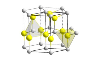 What is Gallium Nitride(GaN)?
19 January 20218365
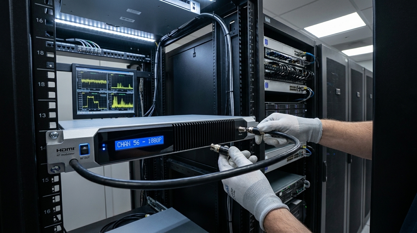 HDMI RF Modulators: Architecture, Setup, Types, and Commercial Applications
18 May 2026307
 Intel Launches Industry's First Stackable, Shareable and Transferable One-Year Semiconductor Technician Certificate Program
26 September 20233104
 What is Relay?
15 November 20217624
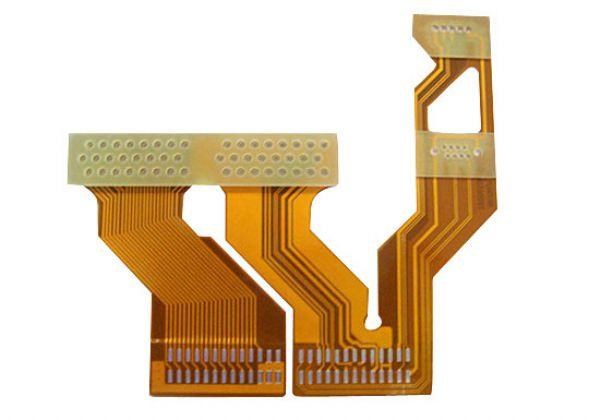 What is FPC (Flexible Printed Circuit)?
26 December 202516035
 MLCC: Applications and Future Development
20 December 20219820
 FPGA: A Highly Customised Type of Chip Based on Digital Circuits
22 February 20234701
 0 Ohm Resistor Explained
10 December 202119793
Analog Devices Inc.
In Stock: 2470
Minimum: 1 Multiples: 1
Qty
Unit Price
Ext Price
1
$148.199628
$148.20
10
$139.810970
$1,398.11
100
$131.897141
$13,189.71
500
$124.431265
$62,215.63
1000
$117.387986
$117,387.99
Not the price you want? Send RFQ Now and we'll contact you ASAP.
Inquire for More Quantity
![ADV7513BSWZ]() ADV7513BSWZ
ADV7513BSWZAnalog Devices, Inc.
![AD9877ABSZ]() AD9877ABSZ
AD9877ABSZAnalog Devices, Inc.
![LTC2245CUH#TRPBF]() LTC2245CUH#TRPBF
LTC2245CUH#TRPBFLinear Technology/Analog Devices
![AD7791BRMZ-REEL]() AD7791BRMZ-REEL
AD7791BRMZ-REELAnalog Devices Inc.
![AD7799BRUZ-REEL]() AD7799BRUZ-REEL
AD7799BRUZ-REELAnalog Devices Inc.
![AD7190BRUZ-REEL]() AD7190BRUZ-REEL
AD7190BRUZ-REELAnalog Devices Inc.
![AD7705BRZ-REEL]() AD7705BRZ-REEL
AD7705BRZ-REELAnalog Devices Inc.
![AD7175-2BRUZ-RL7]() AD7175-2BRUZ-RL7
AD7175-2BRUZ-RL7Analog Devices Inc.
![AD7192BRUZ-REEL]() AD7192BRUZ-REEL
AD7192BRUZ-REELAnalog Devices Inc.
![AD9283BRSZ-RL100]() AD9283BRSZ-RL100
AD9283BRSZ-RL100Analog Devices Inc.


