
 Product
 Brand
Brand Articles
 Tools
Tools
AMD Kintex-7 XC7K480T FPGA: Technical Analysis and Design Guide


3.35mm mm FPGAs Kintex®-7 Series 1156-BBGA, FCBGA 1mm mm
Explore the AMD Kintex-7 XC7K480T FPGA features, including 477k logic cells, 12.5Gbps transceivers, and thermal design tips for high-performance I/O.
Product Introduction
Introduction
The Kintex-7 XC7K480T by AMD (formerly Xilinx) represents a strategic balance point in the 7 Series FPGA portfolio. Built on the 28nm node, this high-density FPGA is engineered to deliver the best price-performance-per-watt for applications requiring massive signal processing capabilities and high-bandwidth I/O. With nearly half a million logic cells and robust DSP resources, the XC7K480T serves as a critical component in next-generation LTE wireless base stations, medical imaging systems, and high-performance computing (HPC) environments where power efficiency cannot compromise throughput.
Key Technical Specifications
The XC7K480T stands out for its high logic density and integrated memory resources. The table below outlines the core operational parameters derived from the manufacturer's specifications.
| Feature | Specification | Conditions |
|---|---|---|
| Logic Cells | 477,760 | Total available logic resources |
| DSP Slices | 1,920 | DSP48E1 slices (25 x 18 multiplier) |
| Total Block RAM | 34,380 Kb | ~35.2 Mb total internal memory |
| Max Transceiver Speed | 12.5 Gbps | GTX Transceivers |
| Operating Voltage | 0.97V to 1.03V | VCCINT Core Voltage |
| Max I/O Pins | 400 | Package dependent (FFG1156) |
| Memory Support | DDR3, DDR3L, LPDDR2 | High-speed memory interfaces |
Architecture & Features
The architecture of the Kintex-7 XC7K480T is optimized for data-intensive processing. At its core, the device integrates 1,920 DSP48E1 slices, making it exceptionally capable of handling complex mathematical operations required in digital signal processing (DSP) and radar applications.
High-Speed Connectivity
The device features high-performance GTX transceivers capable of speeds up to 12.5 Gbps. These transceivers enable support for 10G and 40G wired networking protocols, as well as high-bandwidth video standards. Additionally, the integrated PCI Express Gen2 blocks simplify connectivity to host processors, reducing the soft logic required for interface implementation.
Agile Mixed Signal (AMS)
The inclusion of Agile Mixed Signal (AMS) technology allows for flexible analog-to-digital conversion and system monitoring directly on the chip, reducing the need for external discrete analog components and lowering the overall Bill of Materials (BOM) cost.
Design & Integration Guide
Pinout and Package Layout
The XC7K480T is available in high-density Flip-Chip BGA packages, such as the FFG1156 and FFG901. Proper layout is critical to signal integrity, particularly for the high-speed GTX lanes.
Design Troubleshooting (Pain Points)
Engineers often encounter specific challenges when integrating the XC7K480T into compact designs. Below are common issues and recommended solutions.
1. Thermal Management
Issue: The combination of high logic density (477k cells) and numerous high-speed transceivers generates significant heat, particularly in small form factors.
Solution: It is mandatory to utilize the Xilinx Power Estimator (XPE) early in the design phase to model thermal performance. Designs typically require robust active cooling solutions or large, custom heat sinks to maintain the junction temperature within safe limits.
2. BGA Assembly Complexity
Issue: The FFG1156 and FFG901 packages utilize fine-pitch BGA technology, which complicates PCB fabrication and assembly.
Solution: Designers must ensure their PCB vendor is capable of manufacturing high-layer count boards (often 10+ layers) with 0.8mm to 1.0mm pitch BGA support. Implementing via-in-pad technology is often necessary to break out all I/O signals effectively.
Typical Applications
The XC7K480T is versatile, finding homes in industries ranging from telecommunications to healthcare.
LTE Wireless Base Stations: Utilizing the massive DSP count for beamforming and signal filtering.
10G/40G Wired Networking: Leveraging GTX transceivers for high-throughput data routing.
Broadcast Video Processing: Real-time encoding and decoding of high-definition video streams.
Medical Imaging: Processing data from MRI and CT scanners where precision and speed are paramount.
Comparison: XC7K480T vs. Competitors
When selecting an FPGA in this class, engineers often compare the Kintex-7 against Intel's Arria and Stratix lines, or Microchip's PolarFire.
| Feature | AMD (Xilinx) XC7K480T | Intel Arria 10 GX | Microchip PolarFire MPF500T |
|---|---|---|---|
| Process Node | 28nm | 20nm | 28nm SONOS |
| Focus | Price/Performance/Watt | Mid-range Performance | Low Power / Security |
| Transceivers | GTX (12.5 Gbps) | GT (up to 17.4 Gbps) | 12.7 Gbps |
| DSP Strength | High (1,920 slices) | High (Variable blocks) | Moderate (Math blocks) |
While the Arria 10 GX offers a newer process node and slightly faster transceivers, the XC7K480T remains a dominant choice for legacy designs and systems requiring the specific DSP48E1 architecture. The PolarFire MPF500T is a strong competitor where static power consumption and thermal constraints are the primary concern, though the Kintex-7 often holds the edge in raw ecosystem support and IP availability.
FAQ
Q: What development boards are recommended for the XC7K480T?A: The KC705 Evaluation Kit is the standard reference platform. The Genesys 2 board is another popular option for academic and advanced hobbyist use.
Q: Does the XC7K480T support DDR4 memory?A: Native support is primarily for DDR3, DDR3L, and LPDDR2. DDR4 interfacing may be possible with specific IP and speed grade limitations, but DDR3 is the optimized standard for this generation.
Q: What is the primary advantage of the Kintex-7 over the Artix-7 series?A: The Kintex-7 offers significantly higher logic density, more DSP slices, and faster transceiver speeds (GTX vs. GTP), making it suitable for high-end signal processing rather than just logic control.
Q: Is the XC7K480T susceptible to clone issues?A: Current market signals indicate a "Medium" counterfeit risk. It is strongly advised to purchase through authorized distributors like DigiKey or Avnet to ensure authenticity.
Datasheet & Resources
For complete electrical characteristics, timing diagrams, and package dimensions, refer to the official documentation:
Datasheet: XC7K480T Technical Documentation
Specifications
- TypeParameter
- Factory Lead Time10 Weeks
- Contact Plating
Contact plating (finish) provides corrosion protection for base metals and optimizes the mechanical and electrical properties of the contact interfaces.
Copper, Silver, Tin - Mount
In electronic components, the term "Mount" typically refers to the method or process of physically attaching or fixing a component onto a circuit board or other electronic device. This can involve soldering, adhesive bonding, or other techniques to secure the component in place. The mounting process is crucial for ensuring proper electrical connections and mechanical stability within the electronic system. Different components may have specific mounting requirements based on their size, shape, and function, and manufacturers provide guidelines for proper mounting procedures to ensure optimal performance and reliability of the electronic device.
Surface Mount - Mounting Type
The "Mounting Type" in electronic components refers to the method used to attach or connect a component to a circuit board or other substrate, such as through-hole, surface-mount, or panel mount.
Surface Mount - Package / Case
refers to the protective housing that encases an electronic component, providing mechanical support, electrical connections, and thermal management.
1156-BBGA, FCBGA - Number of I/Os400
- Operating Temperature
The operating temperature is the range of ambient temperature within which a power supply, or any other electrical equipment, operate in. This ranges from a minimum operating temperature, to a peak or maximum operating temperature, outside which, the power supply may fail.
-40°C~100°C TJ - Packaging
Semiconductor package is a carrier / shell used to contain and cover one or more semiconductor components or integrated circuits. The material of the shell can be metal, plastic, glass or ceramic.
Tray - Series
In electronic components, the "Series" refers to a group of products that share similar characteristics, designs, or functionalities, often produced by the same manufacturer. These components within a series typically have common specifications but may vary in terms of voltage, power, or packaging to meet different application needs. The series name helps identify and differentiate between various product lines within a manufacturer's catalog.
Kintex®-7 - Published2010
- JESD-609 Code
The "JESD-609 Code" in electronic components refers to a standardized marking code that indicates the lead-free solder composition and finish of electronic components for compliance with environmental regulations.
e1 - Part Status
Parts can have many statuses as they progress through the configuration, analysis, review, and approval stages.
Active - Moisture Sensitivity Level (MSL)
Moisture Sensitivity Level (MSL) is a standardized rating that indicates the susceptibility of electronic components, particularly semiconductors, to moisture-induced damage during storage and the soldering process, defining the allowable exposure time to ambient conditions before they require special handling or baking to prevent failures
4 (72 Hours) - ECCN Code
An ECCN (Export Control Classification Number) is an alphanumeric code used by the U.S. Bureau of Industry and Security to identify and categorize electronic components and other dual-use items that may require an export license based on their technical characteristics and potential for military use.
3A991.D - Terminal Finish
Terminal Finish refers to the surface treatment applied to the terminals or leads of electronic components to enhance their performance and longevity. It can improve solderability, corrosion resistance, and overall reliability of the connection in electronic assemblies. Common finishes include nickel, gold, and tin, each possessing distinct properties suitable for various applications. The choice of terminal finish can significantly impact the durability and effectiveness of electronic devices.
Tin/Silver/Copper (Sn/Ag/Cu) - HTS Code
HTS (Harmonized Tariff Schedule) codes are product classification codes between 8-1 digits. The first six digits are an HS code, and the countries of import assign the subsequent digits to provide additional classification. U.S. HTS codes are 1 digits and are administered by the U.S. International Trade Commission.
8542.39.00.01 - Voltage - Supply
Voltage - Supply refers to the range of voltage levels that an electronic component or circuit is designed to operate with. It indicates the minimum and maximum supply voltage that can be applied for the device to function properly. Providing supply voltages outside this range can lead to malfunction, damage, or reduced performance. This parameter is critical for ensuring compatibility between different components in a circuit.
0.97V~1.03V - Terminal Position
In electronic components, the term "Terminal Position" refers to the physical location of the connection points on the component where external electrical connections can be made. These connection points, known as terminals, are typically used to attach wires, leads, or other components to the main body of the electronic component. The terminal position is important for ensuring proper connectivity and functionality of the component within a circuit. It is often specified in technical datasheets or component specifications to help designers and engineers understand how to properly integrate the component into their circuit designs.
BOTTOM - Terminal Form
Occurring at or forming the end of a series, succession, or the like; closing; concluding.
BALL - Peak Reflow Temperature (Cel)
Peak Reflow Temperature (Cel) is a parameter that specifies the maximum temperature at which an electronic component can be exposed during the reflow soldering process. Reflow soldering is a common method used to attach electronic components to a circuit board. The Peak Reflow Temperature is crucial because it ensures that the component is not damaged or degraded during the soldering process. Exceeding the specified Peak Reflow Temperature can lead to issues such as component failure, reduced performance, or even permanent damage to the component. It is important for manufacturers and assemblers to adhere to the recommended Peak Reflow Temperature to ensure the reliability and functionality of the electronic components.
NOT SPECIFIED - Supply Voltage
Supply voltage refers to the electrical potential difference provided to an electronic component or circuit. It is crucial for the proper operation of devices, as it powers their functions and determines performance characteristics. The supply voltage must be within specified limits to ensure reliability and prevent damage to components. Different electronic devices have specific supply voltage requirements, which can vary widely depending on their design and intended application.
0.95V - Terminal Pitch
The center distance from one pole to the next.
1mm - Reach Compliance Code
Reach Compliance Code refers to a designation indicating that electronic components meet the requirements set by the Registration, Evaluation, Authorization, and Restriction of Chemicals (REACH) regulation in the European Union. It signifies that the manufacturer has assessed and managed the chemical substances within the components to ensure safety and environmental protection. This code is vital for compliance with regulations aimed at minimizing risks associated with hazardous substances in electronic products.
not_compliant - Time@Peak Reflow Temperature-Max (s)
Time@Peak Reflow Temperature-Max (s) refers to the maximum duration that an electronic component can be exposed to the peak reflow temperature during the soldering process, which is crucial for ensuring reliable solder joint formation without damaging the component.
NOT SPECIFIED - JESD-30 Code
JESD-30 Code refers to a standardized descriptive designation system established by JEDEC for semiconductor-device packages. This system provides a systematic method for generating designators that convey essential information about the package's physical characteristics, such as size and shape, which aids in component identification and selection. By using JESD-30 codes, manufacturers and engineers can ensure consistency and clarity in the specification of semiconductor packages across various applications and industries.
S-PBGA-B1156 - RAM Size
RAM size refers to the amount of random access memory (RAM) available in an electronic component, such as a computer or smartphone. RAM is a type of volatile memory that stores data and instructions that are actively being used by the device's processor. The RAM size is typically measured in gigabytes (GB) and determines how much data the device can store and access quickly for processing. A larger RAM size allows for smoother multitasking, faster loading times, and better overall performance of the electronic component. It is an important factor to consider when choosing a device, especially for tasks that require a lot of memory, such as gaming, video editing, or running multiple applications simultaneously.
4.2MB - Propagation Delay
the flight time of packets over the transmission link and is limited by the speed of light.
110 ps - Programmable Logic Type
Generally, programmable logic devices can be described as being one of three different types: Simple programmable logic devices (SPLD) Complex programmable logic devices (CPLD) Field programmable logic devices (FPGA).
FIELD PROGRAMMABLE GATE ARRAY - Number of Logic Elements/Cells477760
- Total RAM Bits
Total RAM Bits refers to the total number of memory bits that can be stored in a Random Access Memory (RAM) component. RAM is a type of computer memory that allows data to be accessed in any random order, making it faster than other types of memory like hard drives. The total RAM bits indicate the capacity of the RAM chip to store data temporarily for quick access by the computer's processor. The more total RAM bits a component has, the more data it can store and process at any given time, leading to improved performance and multitasking capabilities.
35205120 - Number of LABs/CLBs37325
- Number of Registers597200
- Combinatorial Delay of a CLB-Max
The Combinatorial Delay of a CLB-Max in electronic components refers to the time it takes for a signal to propagate through a combinational logic block (CLB) within a Field-Programmable Gate Array (FPGA) to reach its output. This delay is influenced by factors such as the complexity of the logic function being implemented, the routing resources available, and the physical distance the signal needs to travel within the CLB. Understanding and optimizing the Combinatorial Delay of a CLB-Max is crucial in designing efficient and high-performance digital circuits, as it directly impacts the overall speed and functionality of the FPGA design. By minimizing this delay, designers can achieve faster operation and improved performance in their electronic systems.
0.61 ns - Length35mm
- Height Seated (Max)
Height Seated (Max) is a parameter in electronic components that refers to the maximum allowable height of the component when it is properly seated or installed on a circuit board or within an enclosure. This specification is crucial for ensuring proper fit and alignment within the overall system design. Exceeding the maximum seated height can lead to mechanical interference, electrical shorts, or other issues that may impact the performance and reliability of the electronic device. Manufacturers provide this information to help designers and engineers select components that will fit within the designated space and function correctly in the intended application.
3.35mm - Width35mm
- RoHS Status
RoHS means “Restriction of Certain Hazardous Substances” in the “Hazardous Substances Directive” in electrical and electronic equipment.
ROHS3 Compliant
Parts with Similar Specs
- ImagePart NumberManufacturerPackage / CaseNumber of Logic Elements/CellsNumber of I/ORAM SizeSupply VoltageRoHS StatusTerminal PitchHTS CodeView Compare
![XC7K480T-L2FFG1156I]()
XC7K480T-L2FFG1156I
1156-BBGA, FCBGA
477760
400
4.2 MB
0.95 V
ROHS3 Compliant
1 mm
8542.39.00.01
![XC7K410T-2FFG676C]()
676-BBGA, FCBGA
406720
400
3.5 MB
1 V
ROHS3 Compliant
1 mm
8542.39.00.01
![XC7K410T-L2FFG900I]()
676-BBGA, FCBGA
406720
400
3.5 MB
1 V
ROHS3 Compliant
1 mm
8542.39.00.01
![XC7K410T-1FFG676I]()
900-BBGA, FCBGA
406720
500
3.5 MB
0.95 V
ROHS3 Compliant
1 mm
8542.39.00.01


Datasheet PDF
- Datasheets :
- PCN Design/Specification :
- PCN Packaging :
- Environmental Information :
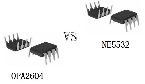 OPA2604 VS NE5532 How to differentiate them?
14 April 202211882
 ICL7107CPLZ A/D Converter: Features, Pinout, and Datasheet
25 February 20223517
 LM211QD Voltage Comparator Overview
14 August 2024789
 TL074ID OP-AMP: Pinout, Specification, and Datasheet
11 June 20213304
 LT8390 Controller: LT8390, DC/DC Controller, Datasheet
05 January 20222862
 J105, JFET Transistor, Junction Field Effect: Datasheet, 3D Model, and Application
19 January 20221728
 A Comprehensive Guide to LTC6945IUFD#TRPBF PLL Frequency Synthesizer
06 March 2024282
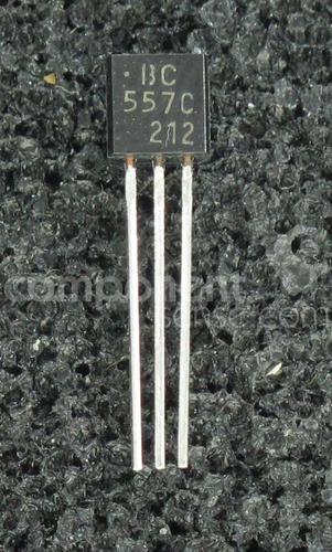 onsemi BC557C Transistor Top Uses for Electronics
18 August 2025231
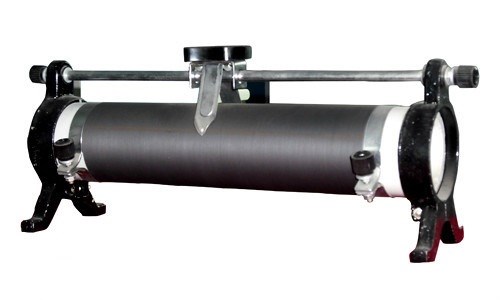 Rheostat Basics: Types, Principle and Functions
25 December 202516508
 Designing a GaN-based Dual Active Bridge for PHEV Chargers
17 May 20242334
 The Ultimate Guide to AI Noise Reduction Translation Earbuds
01 April 20256462
 LED Driver: Function, Types, and Application
01 September 202012830
 LLC Converter with Planar Matrix Transformer for High-Current-High-Power Applications
15 March 20244283
 Types, Structure, and Packages of Integrated Circuits
23 October 202512341
 Electronic components distributor UTMEL Stands Out at electronica china 2024
09 July 20244442
 Introduction to Temperature Sensors
24 October 20259187
Xilinx Inc.
In Stock: 516
United States
China
Canada
Japan
Russia
Germany
United Kingdom
Singapore
Italy
Hong Kong(China)
Taiwan(China)
France
Korea
Mexico
Netherlands
Malaysia
Austria
Spain
Switzerland
Poland
Thailand
Vietnam
India
United Arab Emirates
Afghanistan
Åland Islands
Albania
Algeria
American Samoa
Andorra
Angola
Anguilla
Antigua & Barbuda
Argentina
Armenia
Aruba
Australia
Azerbaijan
Bahamas
Bahrain
Bangladesh
Barbados
Belarus
Belgium
Belize
Benin
Bermuda
Bhutan
Bolivia
Bonaire, Sint Eustatius and Saba
Bosnia & Herzegovina
Botswana
Brazil
British Indian Ocean Territory
British Virgin Islands
Brunei
Bulgaria
Burkina Faso
Burundi
Cabo Verde
Cambodia
Cameroon
Cayman Islands
Central African Republic
Chad
Chile
Christmas Island
Cocos (Keeling) Islands
Colombia
Comoros
Congo
Congo (DRC)
Cook Islands
Costa Rica
Côte d’Ivoire
Croatia
Cuba
Curaçao
Cyprus
Czechia
Denmark
Djibouti
Dominica
Dominican Republic
Ecuador
Egypt
El Salvador
Equatorial Guinea
Eritrea
Estonia
Eswatini
Ethiopia
Falkland Islands
Faroe Islands
Fiji
Finland
French Guiana
French Polynesia
Gabon
Gambia
Georgia
Ghana
Gibraltar
Greece
Greenland
Grenada
Guadeloupe
Guam
Guatemala
Guernsey
Guinea
Guinea-Bissau
Guyana
Haiti
Honduras
Hungary
Iceland
Indonesia
Iran
Iraq
Ireland
Isle of Man
Israel
Jamaica
Jersey
Jordan
Kazakhstan
Kenya
Kiribati
Kosovo
Kuwait
Kyrgyzstan
Laos
Latvia
Lebanon
Lesotho
Liberia
Libya
Liechtenstein
Lithuania
Luxembourg
Macao(China)
Madagascar
Malawi
Maldives
Mali
Malta
Marshall Islands
Martinique
Mauritania
Mauritius
Mayotte
Micronesia
Moldova
Monaco
Mongolia
Montenegro
Montserrat
Morocco
Mozambique
Myanmar
Namibia
Nauru
Nepal
New Caledonia
New Zealand
Nicaragua
Niger
Nigeria
Niue
Norfolk Island
North Korea
North Macedonia
Northern Mariana Islands
Norway
Oman
Pakistan
Palau
Palestinian Authority
Panama
Papua New Guinea
Paraguay
Peru
Philippines
Pitcairn Islands
Portugal
Puerto Rico
Qatar
Réunion
Romania
Rwanda
Samoa
San Marino
São Tomé & Príncipe
Saudi Arabia
Senegal
Serbia
Seychelles
Sierra Leone
Sint Maarten
Slovakia
Slovenia
Solomon Islands
Somalia
South Africa
South Sudan
Sri Lanka
St Helena, Ascension, Tristan da Cunha
St. Barthélemy
St. Kitts & Nevis
St. Lucia
St. Martin
St. Pierre & Miquelon
St. Vincent & Grenadines
Sudan
Suriname
Svalbard & Jan Mayen
Sweden
Syria
Tajikistan
Tanzania
Timor-Leste
Togo
Tokelau
Tonga
Trinidad & Tobago
Tunisia
Turkey
Turkmenistan
Turks & Caicos Islands
Tuvalu
U.S. Outlying Islands
U.S. Virgin Islands
Uganda
Ukraine
Uruguay
Uzbekistan
Vanuatu
Vatican City
Venezuela
Wallis & Futuna
Yemen
Zambia
Zimbabwe
![XC6SLX45-2FGG484C]() XC6SLX45-2FGG484C
XC6SLX45-2FGG484CXilinx Inc.
![XC3S400-4PQG208I]() XC3S400-4PQG208I
XC3S400-4PQG208IXilinx Inc.
![XC6SLX9-2CSG225I]() XC6SLX9-2CSG225I
XC6SLX9-2CSG225IXilinx Inc.
![XCV1000-4BG560C]() XCV1000-4BG560C
XCV1000-4BG560CXilinx Inc.
![XC5VFX130T-2FFG1738I]() XC5VFX130T-2FFG1738I
XC5VFX130T-2FFG1738IXilinx Inc.
![XCV50E-7FG256I]() XCV50E-7FG256I
XCV50E-7FG256IXilinx Inc.
![XC2S400E-6FGG456C]() XC2S400E-6FGG456C
XC2S400E-6FGG456CXilinx Inc.
![XC2S100E-6FT256C]() XC2S100E-6FT256C
XC2S100E-6FT256CXilinx Inc.
![XC2S15-5CS144C]() XC2S15-5CS144C
XC2S15-5CS144CXilinx Inc.
![XCS10-3VQG100C]() XCS10-3VQG100C
XCS10-3VQG100CXilinx Inc.


