

 Product
 Brand
Brand Articles
 Tools
Tools
C106D Thyristor: Circuits, Pinout, and Datasheet [Video]

SCR Sensitive Gate -40°C~110°C 2.2V-On State (Vtm) (Max) 10μA-Current - Off State (Max) 3-Termination Bulk TO-225AA, TO-126-3 Through Hole


SCR Sensitive Gate -40°C~110°C 2.2V-On State (Vtm) (Max) 10μA-Current - Off State (Max) 3-Termination Bulk TO-225AA, TO-126-3 Through Hole
The C106D is a sensitive gate silicon-controlled rectifier, reverse blocking thyristor. This article mainly introduces Circuits, Pinout, Datasheet and other detailed information about Littelfuse Inc. C106D.

3 CIrcuitos con Tiristor C106
C106D Description
Glassivated PNPN devices C106D are ideal for high-volume consumer applications such as temperature, light, and speed control, as well as process and remote control, and warning systems.
C106D Pinout

C106D CAD Model
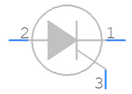
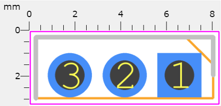
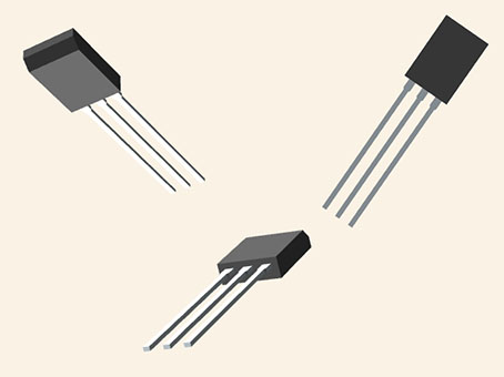
C106D Features
• Glassivated Surface for Reliability and Uniformity
• Power Rated at Economical Prices
• Practical Level Triggering and Holding Characteristics
• Flat, Rugged, Thermopad Construction for Low Thermal Resistance, High Heat Dissipation and Durability
• Sensitive Gate Triggering
• These are Pb−Free Devices
Specifications
- TypeParameter
- Factory Lead Time14 Weeks
- Mounting Type
The "Mounting Type" in electronic components refers to the method used to attach or connect a component to a circuit board or other substrate, such as through-hole, surface-mount, or panel mount.
Through Hole - Package / Case
refers to the protective housing that encases an electronic component, providing mechanical support, electrical connections, and thermal management.
TO-225AA, TO-126-3 - Surface Mount
having leads that are designed to be soldered on the side of a circuit board that the body of the component is mounted on.
NO - Number of Elements1
- Voltage-Off State400V
- Operating Temperature
The operating temperature is the range of ambient temperature within which a power supply, or any other electrical equipment, operate in. This ranges from a minimum operating temperature, to a peak or maximum operating temperature, outside which, the power supply may fail.
-40°C~110°C - Packaging
Semiconductor package is a carrier / shell used to contain and cover one or more semiconductor components or integrated circuits. The material of the shell can be metal, plastic, glass or ceramic.
Bulk - Published2009
- Part Status
Parts can have many statuses as they progress through the configuration, analysis, review, and approval stages.
Active - Moisture Sensitivity Level (MSL)
Moisture Sensitivity Level (MSL) is a standardized rating that indicates the susceptibility of electronic components, particularly semiconductors, to moisture-induced damage during storage and the soldering process, defining the allowable exposure time to ambient conditions before they require special handling or baking to prevent failures
1 (Unlimited) - Number of Terminations3
- HTS Code
HTS (Harmonized Tariff Schedule) codes are product classification codes between 8-1 digits. The first six digits are an HS code, and the countries of import assign the subsequent digits to provide additional classification. U.S. HTS codes are 1 digits and are administered by the U.S. International Trade Commission.
8541.30.00.80 - Terminal Position
In electronic components, the term "Terminal Position" refers to the physical location of the connection points on the component where external electrical connections can be made. These connection points, known as terminals, are typically used to attach wires, leads, or other components to the main body of the electronic component. The terminal position is important for ensuring proper connectivity and functionality of the component within a circuit. It is often specified in technical datasheets or component specifications to help designers and engineers understand how to properly integrate the component into their circuit designs.
SINGLE - Peak Reflow Temperature (Cel)
Peak Reflow Temperature (Cel) is a parameter that specifies the maximum temperature at which an electronic component can be exposed during the reflow soldering process. Reflow soldering is a common method used to attach electronic components to a circuit board. The Peak Reflow Temperature is crucial because it ensures that the component is not damaged or degraded during the soldering process. Exceeding the specified Peak Reflow Temperature can lead to issues such as component failure, reduced performance, or even permanent damage to the component. It is important for manufacturers and assemblers to adhere to the recommended Peak Reflow Temperature to ensure the reliability and functionality of the electronic components.
NOT SPECIFIED - Time@Peak Reflow Temperature-Max (s)
Time@Peak Reflow Temperature-Max (s) refers to the maximum duration that an electronic component can be exposed to the peak reflow temperature during the soldering process, which is crucial for ensuring reliable solder joint formation without damaging the component.
NOT SPECIFIED - Base Part Number
The "Base Part Number" (BPN) in electronic components serves a similar purpose to the "Base Product Number." It refers to the primary identifier for a component that captures the essential characteristics shared by a group of similar components. The BPN provides a fundamental way to reference a family or series of components without specifying all the variations and specific details.
C106 - JESD-30 Code
JESD-30 Code refers to a standardized descriptive designation system established by JEDEC for semiconductor-device packages. This system provides a systematic method for generating designators that convey essential information about the package's physical characteristics, such as size and shape, which aids in component identification and selection. By using JESD-30 codes, manufacturers and engineers can ensure consistency and clarity in the specification of semiconductor packages across various applications and industries.
R-PSFM-T3 - Qualification Status
An indicator of formal certification of qualifications.
Not Qualified - Configuration
The parameter "Configuration" in electronic components refers to the specific arrangement or setup of the components within a circuit or system. It encompasses how individual elements are interconnected and their physical layout. Configuration can affect the functionality, performance, and efficiency of the electronic system, and may influence factors such as signal flow, impedance, and power distribution. Understanding the configuration is essential for design, troubleshooting, and optimizing electronic devices.
SINGLE - Case Connection
Case Connection refers to the method by which an electronic component's case or housing is connected to the electrical circuit. This connection is important for grounding purposes, mechanical stability, and heat dissipation. The case connection can vary depending on the type of component and its intended application. It is crucial to ensure a secure and reliable case connection to maintain the overall performance and safety of the electronic device.
ANODE - Trigger Device Type
Trigger Device Type is a parameter in electronic components that refers to the type of device or mechanism used to initiate a specific action or function within the component. This parameter specifies the specific trigger device, such as a sensor, switch, or signal input, that is required to activate or control the operation of the component. Understanding the trigger device type is crucial for proper integration and operation of the electronic component within a larger system or circuit. By specifying the appropriate trigger device type, engineers and designers can ensure that the component functions correctly and responds to the intended input signals or conditions.
SCR - Voltage - Gate Trigger (Vgt) (Max)
Voltage - Gate Trigger (Vgt) (Max) refers to the maximum voltage level required to trigger the gate of a semiconductor device, such as a thyristor or triac, into the conductive state. When the gate receives this voltage, it initiates the device's conduction, allowing current to flow between its anode and cathode. Exceeding this voltage can lead to unwanted behavior or damage to the component, making it a critical parameter in designing circuits that utilize these devices. Understanding Vgt is essential for ensuring proper operation and reliability in electronic applications.
800mV - Current - Non Rep. Surge 50, 60Hz (Itsm)
The parameter "Current - Non Rep. Surge 50, 60Hz (Itsm)" in electronic components refers to the maximum non-repetitive surge current that a component can withstand without damage during a single surge event at frequencies of 50Hz or 60Hz. This parameter is important for assessing the robustness and reliability of the component in handling sudden spikes or surges in current that may occur in the electrical system. It helps in determining the level of protection needed for the component to ensure its longevity and proper functioning in various operating conditions. Manufacturers provide this specification to guide engineers and designers in selecting the appropriate components for their applications based on the expected surge current levels.
20A @ 60Hz - Current - Gate Trigger (Igt) (Max)
Current - Gate Trigger (Igt) (Max) refers to the maximum gate trigger current required to activate a semiconductor device, such as a thyristor or triac. It is the minimum current that must flow into the gate terminal to ensure that the device turns on and conducts current between its anode and cathode. Exceeding this value can lead to unnecessary power consumption, while insufficient current may prevent the device from turning on effectively. This parameter is crucial for circuit design, as it influences the selection of gate driving circuits.
200μA - Current - Hold (Ih) (Max)
The parameter "Current - Hold (Ih) (Max)" in electronic components refers to the maximum current required to maintain the component in a latched or on-state after it has been triggered. This parameter is commonly associated with relays, switches, and other devices that have a latching function. It is important because it determines the minimum current that must be supplied to keep the component in its activated state, ensuring reliable operation. Exceeding the maximum Ih value can lead to the component failing to hold its state, potentially causing malfunctions or disruptions in the circuit.
3mA - Current - On State (It (RMS)) (Max)
The parameter "Current - On State (It (RMS)) (Max)" refers to the maximum root mean square (RMS) current that an electronic component, typically a semiconductor device like a thyristor or a transistor, can handle while in the on state without sustaining damage. This value is crucial for ensuring that the component operates safely under load conditions. Exceeding this maximum rating can result in overheating, degradation, or failure of the component over time. It is an important specification for designers to consider when selecting components for a circuit to ensure reliable performance.
4A - Repetitive Peak Off-state Voltage
The Repetitive Peak Off-state Voltage (Vdrm) is a key parameter in electronic components, particularly in devices like thyristors and triacs. It refers to the maximum voltage that can be applied across the component when it is in the off-state without triggering it to turn on. This parameter is crucial for ensuring the proper functioning and reliability of the component in various circuit applications. It helps determine the voltage level at which the component can safely operate without experiencing unintended conduction. Designers need to consider the Vdrm rating to prevent damage to the component and maintain the overall performance of the circuit.
400V - Current - On State (It (AV)) (Max)
The parameter "Current - On State (It (AV)) (Max)" in electronic components refers to the maximum average current that a component, typically a switch or semiconductor device, can handle while in the 'on' state without overheating or failing. This rating is crucial for ensuring reliable operation in circuits where the component is subjected to continuous current flow. Exceeding this maximum value can lead to damage or malfunction, so it is important for designers to consider it when selecting components for their applications.
2.55A - SCR Type
SCR Type refers to a category of semiconductor devices specifically designed to control and manage electrical energy in electronic circuits. It stands for Silicon Controlled Rectifier, which is a type of thyristor that can switch and control voltage and current flow. SCRs are commonly used in applications such as motor control, power regulation, and lighting control due to their ability to handle high power loads. The SCR Type includes variations like standard SCRs, gate turn-off thyristors, and triacs, each serving specific purposes in power electronics.
Sensitive Gate - Voltage - On State (Vtm) (Max)
The parameter "Voltage - On State (Vtm) (Max)" refers to the maximum voltage drop across a semiconductor device when it is in the on state and conducting current. It is a critical specification for devices such as transistors, diodes, and thyristors, as it affects the overall power loss and efficiency of the component during operation. A lower Vtm value indicates better efficiency, as it leads to reduced power dissipation in the form of heat. This parameter is essential for engineers to consider when designing circuits that require low voltage drops for optimal performance.
2.2V - Current - Off State (Max)
The parameter "Current - Off State (Max)" refers to the maximum current that can flow through an electronic component when it is in the off state, typically when the component is not conducting electricity. This specification is important for components such as transistors, diodes, and switches, as it indicates the maximum leakage current that can occur when the component is supposed to be non-conductive. Exceeding this maximum off-state current can lead to unintended power consumption, overheating, or malfunction of the component. Designers need to consider this parameter to ensure proper functioning and reliability of the electronic circuit.
10μA - Repetitive Peak Reverse Voltage
The Repetitive Peak Reverse Voltage (VRRM) is a key parameter in electronic components, particularly in diodes and rectifiers. It refers to the maximum reverse voltage that a component can withstand in repetitive peak reverse polarity conditions without breaking down. This parameter is crucial for ensuring the reliable operation and longevity of the component in circuits where reverse voltage may be present intermittently or periodically. It is important to select a component with a VRRM rating higher than the maximum reverse voltage expected in the circuit to prevent damage or failure.
400V - RoHS Status
RoHS means “Restriction of Certain Hazardous Substances” in the “Hazardous Substances Directive” in electrical and electronic equipment.
ROHS3 Compliant
C106D Functional Diagram
The following figure is C106D Functional Diagram.
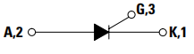
Functional Diagram
C106D Circuit Diagram
The C106D Circuit Diagram is shown as follows.

Circuit Sound SCR Swith by IC 1458 & SCR C106D
Where to use C106D Thyristors
Bell-output Fire-alarms
An SCR (C106D), rather than a relay, can occasionally be used to trigger bell-output fire alarms. The following figure depicts a typical circuit of this type. A standard self-interrupting alarm bell is connected in series with the SCR anode, and gate current is drawn from the positive supply line via the thermostats and current-limiting resistor R1. When the thermostats are open, the SCR and bell are turned off, and the circuit only leaks a little amount of current. When the temperature rises above a certain point, the thermostats close and provide gate current to the SCR via R1, causing the alarm to sound.

SCR-aided Non-latching Fire Alarm
The non-latching form of operation is achieved using the basic Figure circuit. By connecting shunt resistor R3 across the bell as shown in Figure below, the circuit can be made self-latching, ensuring that the SCR's(C106D) anode current does not fall below its latching value when the bell enters self-interrupting mode. The circuit can be reset or unlatched by wiring the push-button switch S2 in series with R3.

SCR-aided Self-latching Fire Alarm
The alarm bell should be chosen with this factor in mind because the SCR used in the two Figure circuits above has a current rating of only 2A. SCRs with a greater current rating can be used instead of the device depicted, however, this will likely entail changes to the R1 and R3 values in the circuits. When the SCR is turned on, about 1V is lost across it, so the circuit's supply line voltage should be about 1V higher than the bell's nominal working voltage.
C106D Alternatives
| Part Number | Description | Manufacturer |
| DRA5ETRIGGER DEVICES | SILICON CONTROLLED RECTIFIER,400V V(DRM),5A I(T),TO-220 | onsemi |
| BT151X-800R,127TRIGGER DEVICES | Silicon Controlled Rectifier, 12A I(T)RMS, 800V V(DRM), 800V V(RRM), 1 Element, TO-220AB, PLASTIC, TO-220F, FULL PACK-3 | WeEn Semiconductor Co Ltd |
| AA118TRIGGER DEVICES | Silicon Controlled Rectifier, 0.3925A I(T)RMS, 500mA I(T), 400V V(DRM), 400V V(RRM), 1 Element, TO-18 | Microsemi Corporation |
| S4006F1TRIGGER DEVICES | Silicon Controlled Rectifier, 6A I(T)RMS, 6000mA I(T), 400V V(DRM), 1 Element, TO-202AB | Loras Industries Inc |
| 2N1771TRIGGER DEVICES | Silicon Controlled Rectifier, 7.4A I(T)RMS, 4700mA I(T), 50V V(DRM), 1 Element, TO-64, TO-64, 2 PIN | Diodes Incorporated |
| CR3AMZ-8TRIGGER DEVICES | Silicon Controlled Rectifier, 0.628A I(T)RMS, 400mA I(T), 400V V(DRM), 400V V(RRM), 1 Element, TO-202B1, 3 PIN | Powerex Power Semiconductors |
| TL2006TRIGGER DEVICES | 3A, 200V, SCR | STMicroelectronics |
| S1010NHTRIGGER DEVICES | Silicon Controlled Rectifier, 6400mA I(T), 800V V(DRM) | Tag Semiconductors Ltd |
| 2N3004TRIGGER DEVICES | Silicon Controlled Rectifier, 0.35A I(T)RMS, 250mA I(T), 200V V(DRM), 200V V(RRM), 1 Element, TO-18 | Semitronics Corp |
| MCR708A1TRIGGER DEVICES | 4A, 600V, SCR | Motorola Mobility LLC |
C106D Applications
• Motor Control
• Industrial and Domestic Lighting
• Heating
• Static Switching
• Temperature, Light, and Speed Control
• Process and Remote Control
• Warning Systems
C106D Package
The following figure is the Package of C106D.
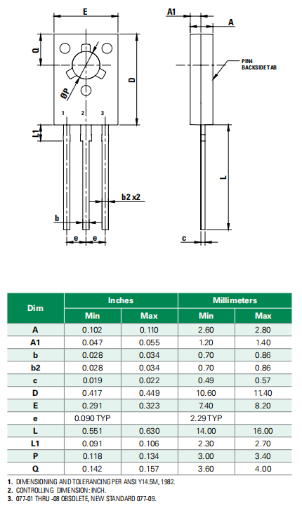
Package
C106D Manufacturer
Littelfuse products are used in a wide range of electrical energy-related applications, from consumer gadgets to cars and industrial buildings. With rising platforms in power regulation and sensing, they have the industry's broadest and deepest array of circuit protection devices. As part of their corporate strategy of accelerated organic expansion and strategic acquisitions, they are growing into complimentary markets. Power semiconductors, heavy-duty switches, magnetic, optical, electromechanical, and temperature sensors, as well as equipment for the safe regulation and distribution of electrical power, are among these markets.
Trend Analysis
Datasheet PDF
- PCN Assembly/Origin :
- Datasheets :
- Environmental Information :
 ADC120 Converter:Datasheet, Application, Pinout
07 September 2021685
 TDA2005 Amplifier: Pinout, Datasheet, Circuit
12 July 202116109
![ATMEGA328-PU Microcontroller : Pinout, Programming [FAQ]](https://res.utmel.com/Images/Article/c648d941-44e2-4526-8779-e1b211c59a17.jpg) ATMEGA328-PU Microcontroller : Pinout, Programming [FAQ]
ATMEGA328-PU Microcontroller : Pinout, Programming [FAQ]15 November 20225392
 TL064 Operational Amplifier: Features, Pinout and Datasheet
16 July 20214348
 A Comprehensive Guide to the 5962-8770203RX Digital to Analog Converter (DAC)
06 March 2024180
 ATmega328P Series: 8-bit AVR Microcontroller Design Guide
15 January 20261711
 L5973D:35V, 250kHz, Pinout and Datasheet
07 March 20221774
 LM224 Operational Amplifier : Application, Pinout and Datasheet
06 September 20214777
 What are Quantum Sensors?
27 October 20212613
 Introduction to Types of Motion Sensors
24 October 202510406
 GenAI Boosts Semiconductor Market with First Revenue Increase in Five Quarters
25 March 20244190
 Tech Giants Accelerate In-House Semiconductor Design, Threatening Fabless Chipmakers
27 September 20233405
 Semiconductor Foundry Market Expected to Reach US$ 161.90 Billion By 2031
26 September 20232225
 What are the Types of Phone Displays?
07 July 20214285
 An Overview of Isolation Transformers
17 September 202015196
 Understanding Electronic Speed Controllers (ESCs): Working Principles, Key Specifications, and Sourcing Guide
15 June 2026747
Littelfuse Inc.
In Stock: 2170
United States
China
Canada
Japan
Russia
Germany
United Kingdom
Singapore
Italy
Hong Kong(China)
Taiwan(China)
France
Korea
Mexico
Netherlands
Malaysia
Austria
Spain
Switzerland
Poland
Thailand
Vietnam
India
United Arab Emirates
Afghanistan
Åland Islands
Albania
Algeria
American Samoa
Andorra
Angola
Anguilla
Antigua & Barbuda
Argentina
Armenia
Aruba
Australia
Azerbaijan
Bahamas
Bahrain
Bangladesh
Barbados
Belarus
Belgium
Belize
Benin
Bermuda
Bhutan
Bolivia
Bonaire, Sint Eustatius and Saba
Bosnia & Herzegovina
Botswana
Brazil
British Indian Ocean Territory
British Virgin Islands
Brunei
Bulgaria
Burkina Faso
Burundi
Cabo Verde
Cambodia
Cameroon
Cayman Islands
Central African Republic
Chad
Chile
Christmas Island
Cocos (Keeling) Islands
Colombia
Comoros
Congo
Congo (DRC)
Cook Islands
Costa Rica
Côte d’Ivoire
Croatia
Cuba
Curaçao
Cyprus
Czechia
Denmark
Djibouti
Dominica
Dominican Republic
Ecuador
Egypt
El Salvador
Equatorial Guinea
Eritrea
Estonia
Eswatini
Ethiopia
Falkland Islands
Faroe Islands
Fiji
Finland
French Guiana
French Polynesia
Gabon
Gambia
Georgia
Ghana
Gibraltar
Greece
Greenland
Grenada
Guadeloupe
Guam
Guatemala
Guernsey
Guinea
Guinea-Bissau
Guyana
Haiti
Honduras
Hungary
Iceland
Indonesia
Iran
Iraq
Ireland
Isle of Man
Israel
Jamaica
Jersey
Jordan
Kazakhstan
Kenya
Kiribati
Kosovo
Kuwait
Kyrgyzstan
Laos
Latvia
Lebanon
Lesotho
Liberia
Libya
Liechtenstein
Lithuania
Luxembourg
Macao(China)
Madagascar
Malawi
Maldives
Mali
Malta
Marshall Islands
Martinique
Mauritania
Mauritius
Mayotte
Micronesia
Moldova
Monaco
Mongolia
Montenegro
Montserrat
Morocco
Mozambique
Myanmar
Namibia
Nauru
Nepal
New Caledonia
New Zealand
Nicaragua
Niger
Nigeria
Niue
Norfolk Island
North Korea
North Macedonia
Northern Mariana Islands
Norway
Oman
Pakistan
Palau
Palestinian Authority
Panama
Papua New Guinea
Paraguay
Peru
Philippines
Pitcairn Islands
Portugal
Puerto Rico
Qatar
Réunion
Romania
Rwanda
Samoa
San Marino
São Tomé & Príncipe
Saudi Arabia
Senegal
Serbia
Seychelles
Sierra Leone
Sint Maarten
Slovakia
Slovenia
Solomon Islands
Somalia
South Africa
South Sudan
Sri Lanka
St Helena, Ascension, Tristan da Cunha
St. Barthélemy
St. Kitts & Nevis
St. Lucia
St. Martin
St. Pierre & Miquelon
St. Vincent & Grenadines
Sudan
Suriname
Svalbard & Jan Mayen
Sweden
Syria
Tajikistan
Tanzania
Timor-Leste
Togo
Tokelau
Tonga
Trinidad & Tobago
Tunisia
Turkey
Turkmenistan
Turks & Caicos Islands
Tuvalu
U.S. Outlying Islands
U.S. Virgin Islands
Uganda
Ukraine
Uruguay
Uzbekistan
Vanuatu
Vatican City
Venezuela
Wallis & Futuna
Yemen
Zambia
Zimbabwe


