
 Product
 Brand
Brand Articles
 Tools
Tools
CC2541 MCU: Pinout, Circuit, Application

TxRx + MCU 2.4GHz 2V~3.6V I2C, SPI, USART 2Mbps 18.3mA~20.8mA - Receiving 17.2mA~18.6mA - Transmitting GFSK, MSK 256kB Flash 8kB RAM 23 40-VFQFN Exposed Pad


TxRx + MCU 2.4GHz 2V~3.6V I2C, SPI, USART 2Mbps 18.3mA~20.8mA - Receiving 17.2mA~18.6mA - Transmitting GFSK, MSK 256kB Flash 8kB RAM 23 40-VFQFN Exposed Pad
The CC2541 is a power-optimized true system-on-chip (SoC) solution for both Bluetooth low energy and proprietary 2.4-GHz applications.

DEMO: Arduino, CC2541 (AT-09, HM10) Bluetooth-Module BLE and 'ATOM FAST' App as a geiger counter
CC2541 Pinout


CC2541 CAD Model
Symbol

Footprint

3D Model

CC2541 Description
The CC2541 is a power-optimized true system-on-chip (SoC) solution for both Bluetooth low energy and proprietary 2.4-GHz applications. It enables robust network nodes to be built with low total bill-of-material costs. It combines the excellent performance of a leading RF transceiver with an industry-standard enhanced 8051 MCU, in-system programmable flash memory, 8-KB RAM, and many other powerful supporting features and peripherals.
CC2541 Features
RF
o 2.4-GHz Bluetooth low energy Compliant and Proprietary RF System-on-Chip
o Supports 250-kbps, 500-kbps, 1-Mbps, 2-Mbps Data Rates
o Excellent Link Budget, Enabling Long-Range Applications Without External Front End
o Programmable Output Power up to 0 dBm
o Excellent Receiver Sensitivity (–94 dBm at 1 Mbps), Selectivity, and Blocking Performance
o Suitable for Systems Targeting Compliance With Worldwide Radio Frequency Regulations: ETSI EN 300 328 and EN 300 440 Class 2 (Europe), FCC CFR47 Part 15 (US), and ARIB STD-T66 (Japan)
· 2.4-GHz Bluetooth low energy Compliant and Proprietary RF System-on-Chip
· Supports 250-kbps, 500-kbps, 1-Mbps, 2-Mbps Data Rates
· Excellent Link Budget, Enabling Long-Range Applications Without External Front End
· Programmable Output Power up to 0 dBm
· Excellent Receiver Sensitivity (–94 dBm at 1 Mbps), Selectivity, and Blocking Performance
· Suitable for Systems Targeting Compliance With Worldwide Radio Frequency Regulations: ETSI EN 300 328 and EN 300 440 Class 2 (Europe), FCC CFR47 Part 15 (US), and ARIB STD-T66 (Japan)
Layout
o Few External Components
o Reference Design Provided
o 6-mm × 6-mm QFN-40 Package
o Pin-Compatible With CC2540 (When Not Using USB or I2C)
· Few External Components
· Reference Design Provided
· 6-mm × 6-mm QFN-40 Package
· Pin-Compatible With CC2540 (When Not Using USB or I2C)
· Low Power
o Active-Mode RX Down to: 17.9 mA
o Active-Mode TX (0 dBm): 18.2 mA
o Power Mode 1 (4-µs Wake-Up): 270 µA
o Power Mode 2 (Sleep Timer On): 1 µA
o Power Mode 3 (External Interrupts): 0.5 µA
o Wide Supply-Voltage Range (2 V–3.6 V)
· Active-Mode RX Down to: 17.9 mA
· Active-Mode TX (0 dBm): 18.2 mA
· Power Mode 1 (4-µs Wake-Up): 270 µA
· Power Mode 2 (Sleep Timer On): 1 µA
· Power Mode 3 (External Interrupts): 0.5 µA
· Wide Supply-Voltage Range (2 V–3.6 V)
· TPS62730 Compatible Low Power in Active Mode
o RX Down to: 14.7 mA (3-V supply)
o TX (0 dBm): 14.3 mA (3-V supply)
· RX Down to: 14.7 mA (3-V supply)
· TX (0 dBm): 14.3 mA (3-V supply)
· Microcontroller
o High-Performance and Low-Power 8051 Microcontroller Core With Code Prefetch
o In-System-Programmable Flash, 128- or 256-KB
o 8-KB RAM With Retention in All Power Modes
o Hardware Debug Support
o Extensive Baseband Automation, Including Auto-Acknowledgment and Address Decoding
o Retention of All Relevant Registers in All Power Modes
· High-Performance and Low-Power 8051 Microcontroller Core With Code Prefetch
· In-System-Programmable Flash, 128- or 256-KB
· 8-KB RAM With Retention in All Power Modes
· Hardware Debug Support
· Extensive Baseband Automation, Including Auto-Acknowledgment
and Address Decoding
· Retention of All Relevant Registers in All Power Modes
· Peripherals
o Powerful Five-Channel DMA
o General-Purpose Timers (One 16-Bit, Two 8-Bit)
o IR Generation Circuitry
o 32-kHz Sleep Timer With Capture
o Accurate Digital RSSI Support
o Battery Monitor and Temperature Sensor
o 12-Bit ADC With Eight Channels and Configurable Resolution
o AES Security Coprocessor
o Two Powerful USARTs With Support for Several Serial Protocols
o 23 General-Purpose I/O Pins
(21 × 4 mA, 2 × 20 mA)
o I2C interface
o 2 I/O Pins Have LED Driving Capabilities
o Watchdog Timer
o Integrated High-PerformanceComparator
· Powerful Five-Channel DMA
· General-Purpose Timers (One 16-Bit, Two 8-Bit)
· IR Generation Circuitry
· 32-kHz Sleep Timer With Capture
· Accurate Digital RSSI Support
· Battery Monitor and Temperature Sensor
· 12-Bit ADC With Eight Channels and Configurable Resolution
· AES Security Coprocessor
· Two Powerful USARTs With Support for Several Serial Protocols
· 23 General-Purpose I/O Pins(21 × 4 mA, 2 × 20 mA)
· I2C interface
· 2 I/O Pins Have LED Driving Capabilities
· Watchdog Timer
· Integrated High-PerformanceComparator
· Development Tools
o CC2541 Evaluation Module Kit (CC2541EMK)
o CC2541 Mini Development Kit (CC2541DK-MINI)
o SmartRF™ Software
o IAR Embedded Workbench™ Available
· CC2541 Evaluation Module Kit (CC2541EMK)
· CC2541 Mini Development Kit (CC2541DK-MINI)
· SmartRF™ Software
· IAR Embedded Workbench™ Available
CC2541 Block Diagram
The CC2541 is highly suited for systems where ultralow power consumption is required. This is specified by various operating modes. Short transition times between operating modes further enable low power consumption.
The simplified block diagram is given below.

The modules can be roughly divided into one of three categories: CPU-related modules; modules related to power, test, and clock distribution, and radio-related modules.
Specifications
- TypeParameter
- Lifecycle Status
Lifecycle Status refers to the current stage of an electronic component in its product life cycle, indicating whether it is active, obsolete, or transitioning between these states. An active status means the component is in production and available for purchase. An obsolete status indicates that the component is no longer being manufactured or supported, and manufacturers typically provide a limited time frame for support. Understanding the lifecycle status is crucial for design engineers to ensure continuity and reliability in their projects.
ACTIVE (Last Updated: 5 days ago) - Factory Lead Time12 Weeks
- Contact Plating
Contact plating (finish) provides corrosion protection for base metals and optimizes the mechanical and electrical properties of the contact interfaces.
Gold - Mount
In electronic components, the term "Mount" typically refers to the method or process of physically attaching or fixing a component onto a circuit board or other electronic device. This can involve soldering, adhesive bonding, or other techniques to secure the component in place. The mounting process is crucial for ensuring proper electrical connections and mechanical stability within the electronic system. Different components may have specific mounting requirements based on their size, shape, and function, and manufacturers provide guidelines for proper mounting procedures to ensure optimal performance and reliability of the electronic device.
Surface Mount - Mounting Type
The "Mounting Type" in electronic components refers to the method used to attach or connect a component to a circuit board or other substrate, such as through-hole, surface-mount, or panel mount.
Surface Mount - Package / Case
refers to the protective housing that encases an electronic component, providing mechanical support, electrical connections, and thermal management.
40-VFQFN Exposed Pad - Number of Pins40
- Operating Temperature
The operating temperature is the range of ambient temperature within which a power supply, or any other electrical equipment, operate in. This ranges from a minimum operating temperature, to a peak or maximum operating temperature, outside which, the power supply may fail.
-40°C~105°C - Packaging
Semiconductor package is a carrier / shell used to contain and cover one or more semiconductor components or integrated circuits. The material of the shell can be metal, plastic, glass or ceramic.
Tape & Reel (TR) - Series
In electronic components, the "Series" refers to a group of products that share similar characteristics, designs, or functionalities, often produced by the same manufacturer. These components within a series typically have common specifications but may vary in terms of voltage, power, or packaging to meet different application needs. The series name helps identify and differentiate between various product lines within a manufacturer's catalog.
Automotive, AEC-Q100 - JESD-609 Code
The "JESD-609 Code" in electronic components refers to a standardized marking code that indicates the lead-free solder composition and finish of electronic components for compliance with environmental regulations.
e4 - Pbfree Code
The "Pbfree Code" parameter in electronic components refers to the code or marking used to indicate that the component is lead-free. Lead (Pb) is a toxic substance that has been widely used in electronic components for many years, but due to environmental concerns, there has been a shift towards lead-free alternatives. The Pbfree Code helps manufacturers and users easily identify components that do not contain lead, ensuring compliance with regulations and promoting environmentally friendly practices. It is important to pay attention to the Pbfree Code when selecting electronic components to ensure they meet the necessary requirements for lead-free applications.
yes - Part Status
Parts can have many statuses as they progress through the configuration, analysis, review, and approval stages.
Active - Moisture Sensitivity Level (MSL)
Moisture Sensitivity Level (MSL) is a standardized rating that indicates the susceptibility of electronic components, particularly semiconductors, to moisture-induced damage during storage and the soldering process, defining the allowable exposure time to ambient conditions before they require special handling or baking to prevent failures
3 (168 Hours) - Number of Terminations40
- ECCN Code
An ECCN (Export Control Classification Number) is an alphanumeric code used by the U.S. Bureau of Industry and Security to identify and categorize electronic components and other dual-use items that may require an export license based on their technical characteristics and potential for military use.
5A992.C - TypeTxRx + MCU
- Voltage - Supply
Voltage - Supply refers to the range of voltage levels that an electronic component or circuit is designed to operate with. It indicates the minimum and maximum supply voltage that can be applied for the device to function properly. Providing supply voltages outside this range can lead to malfunction, damage, or reduced performance. This parameter is critical for ensuring compatibility between different components in a circuit.
2V~3.6V - Terminal Position
In electronic components, the term "Terminal Position" refers to the physical location of the connection points on the component where external electrical connections can be made. These connection points, known as terminals, are typically used to attach wires, leads, or other components to the main body of the electronic component. The terminal position is important for ensuring proper connectivity and functionality of the component within a circuit. It is often specified in technical datasheets or component specifications to help designers and engineers understand how to properly integrate the component into their circuit designs.
QUAD - Terminal Form
Occurring at or forming the end of a series, succession, or the like; closing; concluding.
NO LEAD - Peak Reflow Temperature (Cel)
Peak Reflow Temperature (Cel) is a parameter that specifies the maximum temperature at which an electronic component can be exposed during the reflow soldering process. Reflow soldering is a common method used to attach electronic components to a circuit board. The Peak Reflow Temperature is crucial because it ensures that the component is not damaged or degraded during the soldering process. Exceeding the specified Peak Reflow Temperature can lead to issues such as component failure, reduced performance, or even permanent damage to the component. It is important for manufacturers and assemblers to adhere to the recommended Peak Reflow Temperature to ensure the reliability and functionality of the electronic components.
260 - Number of Functions1
- Supply Voltage
Supply voltage refers to the electrical potential difference provided to an electronic component or circuit. It is crucial for the proper operation of devices, as it powers their functions and determines performance characteristics. The supply voltage must be within specified limits to ensure reliability and prevent damage to components. Different electronic devices have specific supply voltage requirements, which can vary widely depending on their design and intended application.
3V - Terminal Pitch
The center distance from one pole to the next.
0.5mm - Frequency
In electronic components, the parameter "Frequency" refers to the rate at which a signal oscillates or cycles within a given period of time. It is typically measured in Hertz (Hz) and represents how many times a signal completes a full cycle in one second. Frequency is a crucial aspect in electronic components as it determines the behavior and performance of various devices such as oscillators, filters, and communication systems. Understanding the frequency characteristics of components is essential for designing and analyzing electronic circuits to ensure proper functionality and compatibility with other components in a system.
2.4GHz - Time@Peak Reflow Temperature-Max (s)
Time@Peak Reflow Temperature-Max (s) refers to the maximum duration that an electronic component can be exposed to the peak reflow temperature during the soldering process, which is crucial for ensuring reliable solder joint formation without damaging the component.
NOT SPECIFIED - Base Part Number
The "Base Part Number" (BPN) in electronic components serves a similar purpose to the "Base Product Number." It refers to the primary identifier for a component that captures the essential characteristics shared by a group of similar components. The BPN provides a fundamental way to reference a family or series of components without specifying all the variations and specific details.
CC2541 - Interface
In electronic components, the term "Interface" refers to the point at which two different systems, devices, or components connect and interact with each other. It can involve physical connections such as ports, connectors, or cables, as well as communication protocols and standards that facilitate the exchange of data or signals between the connected entities. The interface serves as a bridge that enables seamless communication and interoperability between different parts of a system or between different systems altogether. Designing a reliable and efficient interface is crucial in ensuring proper functionality and performance of electronic components and systems.
I2C, SPI, USART - Memory Size
The memory capacity is the amount of data a device can store at any given time in its memory.
256kB Flash 8kB RAM - RAM Size
RAM size refers to the amount of random access memory (RAM) available in an electronic component, such as a computer or smartphone. RAM is a type of volatile memory that stores data and instructions that are actively being used by the device's processor. The RAM size is typically measured in gigabytes (GB) and determines how much data the device can store and access quickly for processing. A larger RAM size allows for smoother multitasking, faster loading times, and better overall performance of the electronic component. It is an important factor to consider when choosing a device, especially for tasks that require a lot of memory, such as gaming, video editing, or running multiple applications simultaneously.
8kB - Density
In electronic components, "Density" refers to the mass or weight of a material per unit volume. It is a physical property that indicates how tightly packed the atoms or molecules are within the material. The density of a component can affect its performance and characteristics, such as its strength, thermal conductivity, and electrical properties. Understanding the density of electronic components is important for designing and manufacturing processes to ensure optimal performance and reliability.
1002 Mb - Protocol
In electronic components, the parameter "Protocol" refers to a set of rules and standards that govern the communication between devices. It defines the format, timing, sequencing, and error checking methods for data exchange between different components or systems. Protocols ensure that devices can understand and interpret data correctly, enabling them to communicate effectively with each other. Common examples of protocols in electronics include USB, Ethernet, SPI, I2C, and Bluetooth, each with its own specifications for data transmission. Understanding and adhering to protocols is essential for ensuring compatibility and reliable communication between electronic devices.
Bluetooth v4.0 - Power - Output
Power Output in electronic components refers to the amount of electrical power that a device can deliver to a load. It is typically measured in watts and indicates the effectiveness of the component in converting electrical energy into usable work or signal. Power Output can vary based on the component's design, operating conditions, and intended application, making it a critical factor in the performance of amplifiers, power supplies, and other electronic devices. Understanding the Power Output helps in selecting appropriate components for specific applications to ensure efficiency and reliability.
0dBm - RF Family/Standard
The parameter "RF Family/Standard" in electronic components refers to the specific radio frequency (RF) technology or standard that the component complies with or is designed for. RF technology encompasses a wide range of frequencies used for wireless communication, such as Wi-Fi, Bluetooth, cellular networks, and more. Different RF standards dictate the frequency bands, modulation techniques, data rates, and other specifications for communication systems. Understanding the RF family/standard of a component is crucial for ensuring compatibility and optimal performance in RF applications.
Bluetooth - Number of UART Channels1
- Data Rate (Max)
Data Rate (Max) refers to the maximum rate at which data can be transferred or processed within an electronic component or device. It is typically measured in bits per second (bps) or megabits per second (Mbps). This parameter is important for determining the speed and efficiency of data transmission or processing in various electronic applications such as computer systems, networking devices, and memory modules. A higher data rate indicates that the component is capable of handling larger volumes of data at a faster pace, leading to improved performance and responsiveness in electronic systems. It is crucial to consider the Data Rate (Max) specification when selecting electronic components to ensure compatibility and optimal functionality for specific applications.
2Mbps - Serial Interfaces
A serial interface is a communication interface between two digital systems that transmits data as a series of voltage pulses down a wire. Essentially, the serial interface encodes the bits of a binary number by their "temporal" location on a wire rather than their "spatial" location within a set of wires.
I2C, SPI, USART - Current - Receiving
Current - Receiving refers to the amount of electrical current that an electronic component or device is capable of accepting from a power source or another component in a circuit. It indicates the maximum current that can be safely received without causing damage or malfunction. This parameter is crucial for ensuring compatibility and reliability in electronic designs, as exceeding the rated receiving current can lead to overheating or failure of the component.
18.3mA~20.8mA - Current - Transmitting
Current - Transmitting is a parameter used to describe the maximum amount of electrical current that an electronic component can handle while in the transmitting mode. This parameter is crucial for components such as transistors, diodes, and integrated circuits that are involved in transmitting signals or power within a circuit. Exceeding the specified current transmitting rating can lead to overheating, component failure, or even damage to the entire circuit. Designers and engineers must carefully consider this parameter when selecting components to ensure the reliability and performance of the electronic system.
17.2mA~18.6mA - Modulation
In electronic components, modulation refers to the process of varying one or more properties of a periodic waveform, known as the carrier signal, in order to encode information. This modulation technique is commonly used in communication systems to transmit data efficiently over long distances. By modulating the carrier signal, information such as audio, video, or data can be embedded onto the signal for transmission and then demodulated at the receiving end to retrieve the original information. There are various types of modulation techniques, including amplitude modulation (AM), frequency modulation (FM), and phase modulation (PM), each with its own advantages and applications in different communication systems.
GFSK, MSK - Sensitivity (dBm)
Sensitivity (dBm) is a parameter used to measure the minimum input power level required for an electronic component or device to operate effectively. It is typically expressed in decibels relative to one milliwatt (dBm), which is a common unit of power measurement in the field of electronics. A higher sensitivity value indicates that the component can detect weaker input signals, making it more responsive and capable of functioning in low-power conditions. Sensitivity is an important specification for devices like receivers, sensors, and transducers, as it directly impacts their ability to detect and process signals accurately. Manufacturers often provide sensitivity ratings to help users understand the performance capabilities of the component in different operating conditions.
-94 dBm - GPIO
GPIO stands for General Purpose Input/Output. It is a type of electronic pin found on microcontrollers, microprocessors, and other integrated circuits that can be configured to either input or output digital signals. GPIO pins can be used to connect and communicate with external devices such as sensors, LEDs, motors, and more. They provide a flexible way to interact with the physical world by allowing the device to both receive and send digital signals. GPIO pins can be programmed and controlled by software to perform various functions based on the specific requirements of the electronic system.
23 - Height1mm
- Length6mm
- Width6mm
- Thickness
Thickness in electronic components refers to the measurement of how thick a particular material or layer is within the component structure. It can pertain to various aspects, such as the thickness of a substrate, a dielectric layer, or conductive traces. This parameter is crucial as it impacts the electrical, mechanical, and thermal properties of the component, influencing its performance and reliability in electronic circuits.
900μm - RoHS Status
RoHS means “Restriction of Certain Hazardous Substances” in the “Hazardous Substances Directive” in electrical and electronic equipment.
ROHS3 Compliant - Lead Free
Lead Free is a term used to describe electronic components that do not contain lead as part of their composition. Lead is a toxic material that can have harmful effects on human health and the environment, so the electronics industry has been moving towards lead-free components to reduce these risks. Lead-free components are typically made using alternative materials such as silver, copper, and tin. Manufacturers must comply with regulations such as the Restriction of Hazardous Substances (RoHS) directive to ensure that their products are lead-free and environmentally friendly.
Lead Free
CC2541 Application
• 2.4-GHz Bluetooth low energy Systems
• Proprietary 2.4-GHz Systems
• Human-Interface Devices (Keyboard, Mouse, Remote Control)
• Sports and Leisure Equipment
• Mobile Phone Accessories
• Consumer Electronics
CC2541 Typical Application Circuit

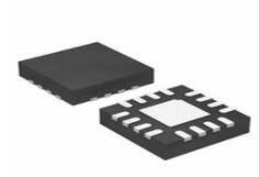
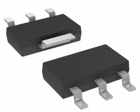
CC2541 Package

CC2541 Manufacturer
As a global semiconductor company operating in 35 countries, Texas Instruments (TI) is first and foremost a reflection of its people. From the TIer who unveiled the first working integrated circuit in 1958 to the more than 30,000 TIers around the world today who design, manufacture and sell analogue and embedded processing chips, TIers are problem-solvers collaborating to change the world through technology.
Datasheet PDF
- Datasheets :
Popularity by Region
What is CC2541?
The CC2541 is a power-optimized true system-on-chip (SoC) solution for both Bluetooth low energy and proprietary 2.4-GHz applications. Compared to the CC2540, the CC2541 provides lower RF current consumption. The CC2541 does not have the USB interface of the CC2540 and provides lower maximum output power in TX mode.
What is TPS62730 and What is the relationship between CC2541 and TPS62730?
• TPS62730 is a 2-MHz Step-Down Converter Single-Mode
• Extends Battery Lifetime by up to 20%
• Reduced Current in All Active Modes
• 30-nA Bypass Mode Current to Support Power Modes Roles
• RF Performance Unchanged
• Small Package Allows for Small Solution Size
• CC2541 Controllable
 TPS22918TDBVRQ1 On-Resistance Load Switch: Schematic, Pinout, and Datasheet
02 April 20226991
 LM35 Sensor: Pinout, Alternatives and Datasheet
26 August 202113639
 TPS51219RTER Controller: Datasheet, Price, Application Circuit
23 March 20221407
![LR41 Battery, LR41 Battery Equivalent, LR41 and SR41 Cell Battery [FAQ]](https://res.utmel.com/Images/Article/edaf2000-e788-42b0-b239-6f7d52115528.jpg) LR41 Battery, LR41 Battery Equivalent, LR41 and SR41 Cell Battery [FAQ]
LR41 Battery, LR41 Battery Equivalent, LR41 and SR41 Cell Battery [FAQ]20 December 202133417
 A Comprehensive Guide to LTC691CSW#TRPBF PMIC Supervisors
06 March 2024206
 LT1013 Dual Precision Op Amp: Pinout, Equivalent and Datasheet
19 November 20214897
 STM32F101VBT6 Microcontroller: Features, Specifications and Datasheet
14 August 20241093
 UA78M05CDCYR: Equivalents, Circuit, Pinout
26 March 2022909
 50 World Famous Sensor Manufacturing Companies
31 October 2025897105
 Apple Will Help TSMC to Be in the Leading Position in the Next Era
16 March 20223442
 US Energy Department Funds Next-Gen Semiconductor Projects to Improve Power Grids
09 December 20234023
 Hybrid Sources Powered Electric Vehicles - Part 1
08 March 20233463
 Exploring SPI Communication for Faster Data Transfer
20 June 20251463
 Why Meta Did Not Choose Qualcomm AI Chip?
02 April 20225987
 Electronic Components in Aerospace Aircraft
15 March 20243981
 The Understanding to Autonomous Driving Sensor
10 November 20211330
Texas Instruments
In Stock: 2500
United States
China
Canada
Japan
Russia
Germany
United Kingdom
Singapore
Italy
Hong Kong(China)
Taiwan(China)
France
Korea
Mexico
Netherlands
Malaysia
Austria
Spain
Switzerland
Poland
Thailand
Vietnam
India
United Arab Emirates
Afghanistan
Åland Islands
Albania
Algeria
American Samoa
Andorra
Angola
Anguilla
Antigua & Barbuda
Argentina
Armenia
Aruba
Australia
Azerbaijan
Bahamas
Bahrain
Bangladesh
Barbados
Belarus
Belgium
Belize
Benin
Bermuda
Bhutan
Bolivia
Bonaire, Sint Eustatius and Saba
Bosnia & Herzegovina
Botswana
Brazil
British Indian Ocean Territory
British Virgin Islands
Brunei
Bulgaria
Burkina Faso
Burundi
Cabo Verde
Cambodia
Cameroon
Cayman Islands
Central African Republic
Chad
Chile
Christmas Island
Cocos (Keeling) Islands
Colombia
Comoros
Congo
Congo (DRC)
Cook Islands
Costa Rica
Côte d’Ivoire
Croatia
Cuba
Curaçao
Cyprus
Czechia
Denmark
Djibouti
Dominica
Dominican Republic
Ecuador
Egypt
El Salvador
Equatorial Guinea
Eritrea
Estonia
Eswatini
Ethiopia
Falkland Islands
Faroe Islands
Fiji
Finland
French Guiana
French Polynesia
Gabon
Gambia
Georgia
Ghana
Gibraltar
Greece
Greenland
Grenada
Guadeloupe
Guam
Guatemala
Guernsey
Guinea
Guinea-Bissau
Guyana
Haiti
Honduras
Hungary
Iceland
Indonesia
Iran
Iraq
Ireland
Isle of Man
Israel
Jamaica
Jersey
Jordan
Kazakhstan
Kenya
Kiribati
Kosovo
Kuwait
Kyrgyzstan
Laos
Latvia
Lebanon
Lesotho
Liberia
Libya
Liechtenstein
Lithuania
Luxembourg
Macao(China)
Madagascar
Malawi
Maldives
Mali
Malta
Marshall Islands
Martinique
Mauritania
Mauritius
Mayotte
Micronesia
Moldova
Monaco
Mongolia
Montenegro
Montserrat
Morocco
Mozambique
Myanmar
Namibia
Nauru
Nepal
New Caledonia
New Zealand
Nicaragua
Niger
Nigeria
Niue
Norfolk Island
North Korea
North Macedonia
Northern Mariana Islands
Norway
Oman
Pakistan
Palau
Palestinian Authority
Panama
Papua New Guinea
Paraguay
Peru
Philippines
Pitcairn Islands
Portugal
Puerto Rico
Qatar
Réunion
Romania
Rwanda
Samoa
San Marino
São Tomé & Príncipe
Saudi Arabia
Senegal
Serbia
Seychelles
Sierra Leone
Sint Maarten
Slovakia
Slovenia
Solomon Islands
Somalia
South Africa
South Sudan
Sri Lanka
St Helena, Ascension, Tristan da Cunha
St. Barthélemy
St. Kitts & Nevis
St. Lucia
St. Martin
St. Pierre & Miquelon
St. Vincent & Grenadines
Sudan
Suriname
Svalbard & Jan Mayen
Sweden
Syria
Tajikistan
Tanzania
Timor-Leste
Togo
Tokelau
Tonga
Trinidad & Tobago
Tunisia
Turkey
Turkmenistan
Turks & Caicos Islands
Tuvalu
U.S. Outlying Islands
U.S. Virgin Islands
Uganda
Ukraine
Uruguay
Uzbekistan
Vanuatu
Vatican City
Venezuela
Wallis & Futuna
Yemen
Zambia
Zimbabwe
![CC1310F128RGZT]() CC1310F128RGZT
CC1310F128RGZTTexas Instruments
![CC2650F128RSMT]() CC2650F128RSMT
CC2650F128RSMTTexas Instruments
![CC1101RGPR]() CC1101RGPR
CC1101RGPRTexas Instruments
![CC1125RHBR]() CC1125RHBR
CC1125RHBRTexas Instruments
![CC1110F32RHHR]() CC1110F32RHHR
CC1110F32RHHRTexas Instruments
![CC430F5137IRGZR]() CC430F5137IRGZR
CC430F5137IRGZRTexas Instruments
![CC2540F256RHAR]() CC2540F256RHAR
CC2540F256RHARTexas Instruments
![CC1310F128RHBR]() CC1310F128RHBR
CC1310F128RHBRTexas Instruments
![CC2640F128RHBR]() CC2640F128RHBR
CC2640F128RHBRTexas Instruments
![CC2564BRVMT]() CC2564BRVMT
CC2564BRVMTTexas Instruments


