Product
 Brand
Brand Articles
 Tools
Tools
CST-1005 Transformer: Pinout, Datasheet, CAD Model
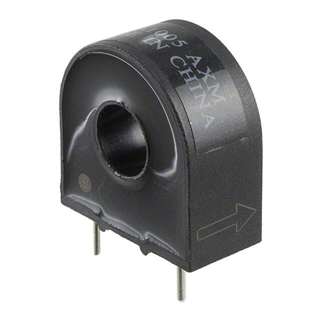
TRIAD MAGNETICS CST-1005 TRANSFORMER, 1000:1, 5A, 40OHM
Unit Price: $5.279409
Ext Price: $5.28


TRIAD MAGNETICS CST-1005 TRANSFORMER, 1000:1, 5A, 40OHM
CST-1005 is a current sense transformer, which is one of the CST series. This article mainly covers its pinout, datasheet and more detailed information about CST1005.

Triad Magnetics Current Sensors Product Demo
CST-1005 Description
CST1005 current sense transformer is used to detect the current passing through a conductor that is very reliable and operate effectively between 50-60 Hz.
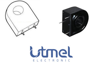
CST-1005 Pinout
CST-1005 CAD Model
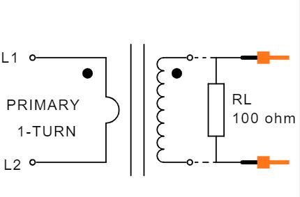
Symbol
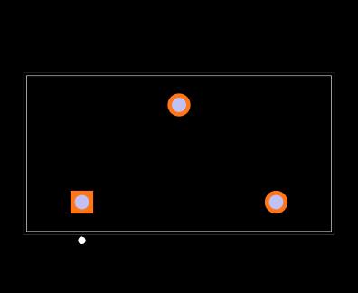
Footprint
3D Model
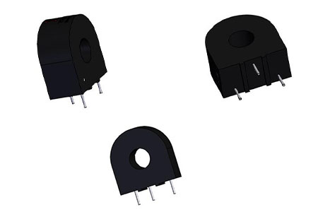
CST-1005 Features
UL rated 130ºC materials.
Operate efficiently at 50/60 HZ.
Turns Ratio:1000:1.
Specifications
- TypeParameter
- Factory Lead Time17 Weeks
- Mount
In electronic components, the term "Mount" typically refers to the method or process of physically attaching or fixing a component onto a circuit board or other electronic device. This can involve soldering, adhesive bonding, or other techniques to secure the component in place. The mounting process is crucial for ensuring proper electrical connections and mechanical stability within the electronic system. Different components may have specific mounting requirements based on their size, shape, and function, and manufacturers provide guidelines for proper mounting procedures to ensure optimal performance and reliability of the electronic device.
PCB, Through Hole - Mounting Type
The "Mounting Type" in electronic components refers to the method used to attach or connect a component to a circuit board or other substrate, such as through-hole, surface-mount, or panel mount.
Through Hole - Weight0.044lb 19.96g
- Packaging
Semiconductor package is a carrier / shell used to contain and cover one or more semiconductor components or integrated circuits. The material of the shell can be metal, plastic, glass or ceramic.
Bulk - Series
In electronic components, the "Series" refers to a group of products that share similar characteristics, designs, or functionalities, often produced by the same manufacturer. These components within a series typically have common specifications but may vary in terms of voltage, power, or packaging to meet different application needs. The series name helps identify and differentiate between various product lines within a manufacturer's catalog.
CST - Published2006
- Size / Dimension
In electronic components, the parameter "Size / Dimension" refers to the physical dimensions of the component, such as its length, width, and height. These dimensions are crucial for determining how the component will fit into a circuit or system, as well as for ensuring compatibility with other components and the overall design requirements. The size of a component can also impact its performance characteristics, thermal properties, and overall functionality within a given application. Engineers and designers must carefully consider the size and dimensions of electronic components to ensure proper integration and functionality within their designs.
0.925Lx0.472W 23.50mmx12.00mm - Part Status
Parts can have many statuses as they progress through the configuration, analysis, review, and approval stages.
Active - Moisture Sensitivity Level (MSL)
Moisture Sensitivity Level (MSL) is a standardized rating that indicates the susceptibility of electronic components, particularly semiconductors, to moisture-induced damage during storage and the soldering process, defining the allowable exposure time to ambient conditions before they require special handling or baking to prevent failures
Not Applicable - Termination
Termination in electronic components refers to the practice of matching the impedance of a circuit to prevent signal reflections and ensure maximum power transfer. It involves the use of resistors or other components at the end of transmission lines or connections. Proper termination is crucial in high-frequency applications to maintain signal integrity and reduce noise.
PC Pin - TypeNon-Invasive (Solid Core)
- Power Rating
The "Power Rating" of an electronic component refers to the maximum amount of power that the component can handle or dissipate without being damaged. It is typically measured in watts and is an important specification to consider when designing or selecting components for a circuit. Exceeding the power rating of a component can lead to overheating, malfunction, or even permanent damage. It is crucial to ensure that the power rating of each component in a circuit is sufficient to handle the power levels expected during normal operation to maintain the reliability and longevity of the electronic system.
2.5mW - Current Rating
Current rating is the maximum current that a fuse will carry for an indefinite period without too much deterioration of the fuse element.
5A - Frequency
In electronic components, the parameter "Frequency" refers to the rate at which a signal oscillates or cycles within a given period of time. It is typically measured in Hertz (Hz) and represents how many times a signal completes a full cycle in one second. Frequency is a crucial aspect in electronic components as it determines the behavior and performance of various devices such as oscillators, filters, and communication systems. Understanding the frequency characteristics of components is essential for designing and analyzing electronic circuits to ensure proper functionality and compatibility with other components in a system.
60Hz - Termination Style
"Termination style" in electronic components refers to the method used to connect the component to a circuit board or other electronic devices. It determines how the component's leads or terminals are designed for soldering or mounting onto the circuit board. Common termination styles include through-hole, surface mount, and wire lead terminations.Through-hole components have leads that are inserted through holes in the circuit board and soldered on the other side. Surface mount components have flat terminals that are soldered directly onto the surface of the circuit board. Wire lead terminations involve attaching wires to the component for connection.The choice of termination style depends on factors such as the type of component, the manufacturing process, and the space available on the circuit board. Different termination styles offer various advantages in terms of ease of assembly, reliability, and space efficiency in electronic designs.
PC Pin - Approval Agency
The parameter "Approval Agency" in electronic components refers to the organization responsible for testing and certifying that a component meets specific safety, quality, and performance standards. These agencies evaluate products to ensure compliance with industry regulations and standards, providing assurance to manufacturers and consumers. Approval from recognized agencies can enhance a component's marketability and acceptance in various applications, particularly in sectors like automotive, aerospace, and healthcare. Common approval agencies include Underwriters Laboratories (UL), International Electrotechnical Commission (IEC), and the American National Standards Institute (ANSI).
UL - DC Resistance (DCR)
DC Resistance (DCR) is a measure of the resistance of an electronic component when a direct current (DC) is applied. It quantifies how much opposition the component presents to the flow of electrical current under steady-state conditions. DCR is crucial for understanding power loss, heating, and efficient performance in circuits, as it affects the overall behavior of components such as inductors, transformers, and resistors. Lower DCR values typically indicate better efficiency and performance in a given application.
40Ohm - Wire/Cable Diameter
Wire/Cable Diameter refers to the measurement of the thickness of a wire or cable. This dimension is crucial as it influences the electrical resistance, current-carrying capacity, and overall performance of the component. A larger diameter typically allows for greater current flow and reduces resistance, while a smaller diameter can limit these attributes. The diameter is often specified in units such as millimeters or American Wire Gauge (AWG) numbers.
35 mm - Frequency Range
A continuous range or spectrum of frequencies that extends from one limiting frequency to another.
50/60Hz - Input Current
Input current is a parameter that refers to the amount of electrical current flowing into a specific electronic component or device. It is typically measured in amperes (A) and represents the current required for the component to operate properly. Understanding the input current is important for designing circuits and power supplies, as it helps determine the capacity and compatibility of the components being used. Monitoring the input current also helps ensure that the component is not being overloaded or underpowered, which can affect its performance and longevity.
5A - Current Ratio
The Current Ratio in electronic components refers to the ratio of the maximum continuous current that a component can handle to its rated current. It is a crucial parameter that indicates the component's ability to handle current without overheating or failing. A higher current ratio means that the component can handle higher currents safely, while a lower ratio indicates that the component may be more prone to failure under high current conditions. It is important to consider the Current Ratio when designing circuits to ensure that components are not being operated beyond their specified limits.
1000:1 - Primary Current
Primary Current refers to the amount of electric current flowing through the primary winding of a transformer or inductor. It is a critical parameter that influences the energy transfer between the primary and secondary windings. In the context of a transformer, the primary current is essential for determining the transformer’s efficiency, power rating, and performance characteristics. Understanding primary current helps in designing circuits and selecting appropriate components to ensure proper functionality and safety.
5A - Height24.8mm
- Height Seated (Max)
Height Seated (Max) is a parameter in electronic components that refers to the maximum allowable height of the component when it is properly seated or installed on a circuit board or within an enclosure. This specification is crucial for ensuring proper fit and alignment within the overall system design. Exceeding the maximum seated height can lead to mechanical interference, electrical shorts, or other issues that may impact the performance and reliability of the electronic device. Manufacturers provide this information to help designers and engineers select components that will fit within the designated space and function correctly in the intended application.
0.976 24.80mm - REACH SVHC
The parameter "REACH SVHC" in electronic components refers to the compliance with the Registration, Evaluation, Authorization, and Restriction of Chemicals (REACH) regulation regarding Substances of Very High Concern (SVHC). SVHCs are substances that may have serious effects on human health or the environment, and their use is regulated under REACH to ensure their safe handling and minimize their impact.Manufacturers of electronic components need to declare if their products contain any SVHCs above a certain threshold concentration and provide information on the safe use of these substances. This information allows customers to make informed decisions about the potential risks associated with using the components and take appropriate measures to mitigate any hazards.Ensuring compliance with REACH SVHC requirements is essential for electronics manufacturers to meet regulatory standards, protect human health and the environment, and maintain transparency in their supply chain. It also demonstrates a commitment to sustainability and responsible manufacturing practices in the electronics industry.
Unknown - RoHS Status
RoHS means “Restriction of Certain Hazardous Substances” in the “Hazardous Substances Directive” in electrical and electronic equipment.
ROHS3 Compliant - Lead Free
Lead Free is a term used to describe electronic components that do not contain lead as part of their composition. Lead is a toxic material that can have harmful effects on human health and the environment, so the electronics industry has been moving towards lead-free components to reduce these risks. Lead-free components are typically made using alternative materials such as silver, copper, and tin. Manufacturers must comply with regulations such as the Restriction of Hazardous Substances (RoHS) directive to ensure that their products are lead-free and environmentally friendly.
Lead Free
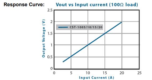
CST-1005 Response Curve
CST-1005 Manufacturer
For over 70 years, consumer, commercial and industrial electronic devices have relied on innovative magnetics technology from Triad Magnetics. They offer solutions for power conversion, filtering, isolation and more. Their products include transformers for audio, gate drive, power, medical/dental, wall-mount and plug-in applications; as well as inductors for current sense, common mode, toroidal, filtering and power applications.
CST-1005 Dimensions

Datasheet PDF
- Datasheets :
- Other Related Documents :
 TXB0108PWR Translator:Features, Applications and Datasheet
23 October 20231156
 TLV320AIC3104IRHBR Audio Codec: Pinout, Datasheet, and Alternatives
25 March 20222248
 HC-06 vs. HC-05 Bluetooth Module: What is the difference between HC-06 and HC-05?
24 November 202163246
 MAX31856 Digital Converter: Datasheet, Pinout and Schematic
12 August 20218002
 Understanding the STM32L151CBT6A Microcontroller in Detail
07 June 2025305
 CR1632 Battery: Equivalent, Pinout and Application
03 September 202157302
 MCP1703 LDO Voltage Regulator: Datasheet pdf, Pinout and Application
29 November 20213810
 TDA7297 vs. TPA3116D2 : Which one is better?
01 March 20229320
 Electronic Components in Consumer Electronics: Types, Functions, and Future Trends
01 December 20234800
 The Ultimate Guide to Maintaining Your L1154 Battery
16 June 2025976
 Photocoupler Basis: Description, Applications and Working Principle
29 September 202110745
 Introduction to Flyback Transformer
29 January 202111968
 What is a Polypropylene Capacitor?
08 November 202121815
 The Rise of Co-Packaged Optics (CPO) and Silicon Photonics in AI Superclusters
24 June 20262672
 Vibration Isolator: Types and Applications
13 January 202112866
 JSCJ Authorized Distributor | UTMEL Electronics
21 November 20234255
Triad Magnetics
In Stock: 45
Minimum: 1 Multiples: 1
Qty
Unit Price
Ext Price
1
$5.279409
$5.28
10
$4.980575
$49.81
100
$4.698655
$469.87
500
$4.432694
$2,216.35
1000
$4.181786
$4,181.79
Not the price you want? Send RFQ Now and we'll contact you ASAP.
Inquire for More Quantity
![CST206-1A]() CST206-1A
CST206-1ATriad Magnetics
![CSE187L]() CSE187L
CSE187LTriad Magnetics
![CSE5-101001]() CSE5-101001
CSE5-101001Triad Magnetics
![CST-1010]() CST-1010
CST-1010Triad Magnetics
![CST306-3A]() CST306-3A
CST306-3ATriad Magnetics
![CSE5-101251]() CSE5-101251
CSE5-101251Triad Magnetics
![CSE184L]() CSE184L
CSE184LTriad Magnetics
![CSE187L-P]() CSE187L-P
CSE187L-PTriad Magnetics
![CSE187L-B]() CSE187L-B
CSE187L-BTriad Magnetics