
 Product
 Brand
Brand Articles
 Tools
Tools
TXB0108PWR Translator:Features, Applications and Datasheet
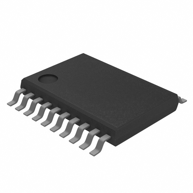
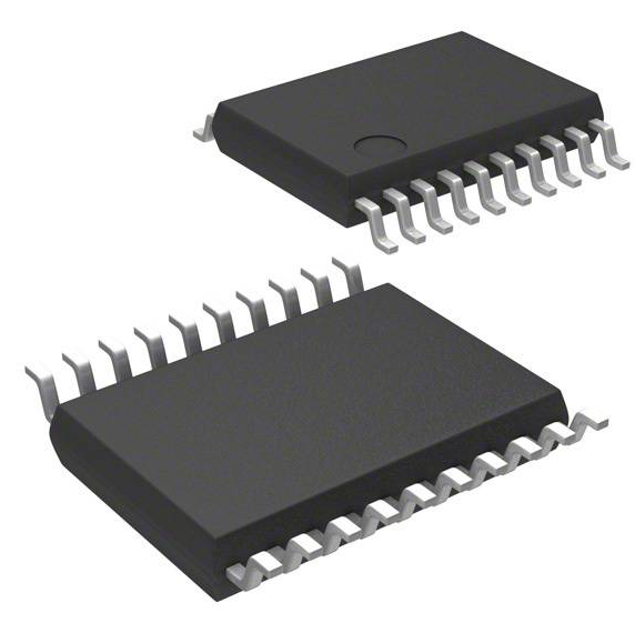
Surface Mount 20 pins Tape & Reel (TR) Voltage Translators & Level Shifters 1 Voltage Level 20-TSSOP (0.173, 4.40mm Width) Active 6 Weeks Weeks 1 (Unlimited)


Surface Mount 20 pins Tape & Reel (TR) Voltage Translators & Level Shifters 1 Voltage Level 20-TSSOP (0.173, 4.40mm Width) Active 6 Weeks Weeks 1 (Unlimited)
Texas Instruments TXB0108PWR is a voltage level translator that can convert signals between different voltage levels. This article will introduce its features, applications and datasheet.
TXB0108PWR Description
Texas Instruments TXB0108PWR is a voltage level translator that can convert signals between different voltage levels. It has 8-bit bidirectional capability, which means it can transfer data in both directions between two devices with different logic levels. It also has auto direction sensing feature, which means it can automatically detect the direction of data flow without any external control signals. It can support data rates up to 100 Mbps and has +/-15-kV ESD protection for high reliability. It comes in a TSSOP-20 package and operates in a temperature range of -40°C to +85°C.
TXB0108PWR Features
It is a voltage level translator that can convert signals between different voltage levels, such as 1.2 V, 1.8 V, 2.5 V, 3.3 V, and 5 V.
It has 8-bit bidirectional capability, which means it can transfer data in both directions between two devices with different logic levels.
It has auto direction sensing feature, which means it can automatically detect the direction of data flow without any external control signals.
It can support data rates up to 100 Mbps and has +/-15-kV ESD protection for high reliability.
It comes in a TSSOP-20 package and operates in a temperature range of -40°C to +85°C.
It is compatible with I2C, SMBus, PMBus, and other open-drain and push-pull applications.
Specifications
- TypeParameter
- Lifecycle Status
Lifecycle Status refers to the current stage of an electronic component in its product life cycle, indicating whether it is active, obsolete, or transitioning between these states. An active status means the component is in production and available for purchase. An obsolete status indicates that the component is no longer being manufactured or supported, and manufacturers typically provide a limited time frame for support. Understanding the lifecycle status is crucial for design engineers to ensure continuity and reliability in their projects.
ACTIVE (Last Updated: 4 days ago) - Factory Lead Time6 Weeks
- Contact Plating
Contact plating (finish) provides corrosion protection for base metals and optimizes the mechanical and electrical properties of the contact interfaces.
Gold - Mount
In electronic components, the term "Mount" typically refers to the method or process of physically attaching or fixing a component onto a circuit board or other electronic device. This can involve soldering, adhesive bonding, or other techniques to secure the component in place. The mounting process is crucial for ensuring proper electrical connections and mechanical stability within the electronic system. Different components may have specific mounting requirements based on their size, shape, and function, and manufacturers provide guidelines for proper mounting procedures to ensure optimal performance and reliability of the electronic device.
Surface Mount - Mounting Type
The "Mounting Type" in electronic components refers to the method used to attach or connect a component to a circuit board or other substrate, such as through-hole, surface-mount, or panel mount.
Surface Mount - Package / Case
refers to the protective housing that encases an electronic component, providing mechanical support, electrical connections, and thermal management.
20-TSSOP (0.173, 4.40mm Width) - Number of Pins20
- Weight76.997305mg
- Manufacturer Package Identifier
The Manufacturer Package Identifier is a unique code or label assigned by the manufacturer to identify a specific package or housing style of an electronic component. This identifier helps in distinguishing between different package types of the same component, such as integrated circuits, transistors, or diodes. It typically includes information about the package dimensions, lead configuration, and other physical characteristics of the component. The Manufacturer Package Identifier is crucial for ensuring compatibility and proper assembly of electronic components in various devices and circuits.
PW (R-PDSO-G**) - Operating Temperature
The operating temperature is the range of ambient temperature within which a power supply, or any other electrical equipment, operate in. This ranges from a minimum operating temperature, to a peak or maximum operating temperature, outside which, the power supply may fail.
-40°C~85°C TA - Packaging
Semiconductor package is a carrier / shell used to contain and cover one or more semiconductor components or integrated circuits. The material of the shell can be metal, plastic, glass or ceramic.
Tape & Reel (TR) - JESD-609 Code
The "JESD-609 Code" in electronic components refers to a standardized marking code that indicates the lead-free solder composition and finish of electronic components for compliance with environmental regulations.
e4 - Pbfree Code
The "Pbfree Code" parameter in electronic components refers to the code or marking used to indicate that the component is lead-free. Lead (Pb) is a toxic substance that has been widely used in electronic components for many years, but due to environmental concerns, there has been a shift towards lead-free alternatives. The Pbfree Code helps manufacturers and users easily identify components that do not contain lead, ensuring compliance with regulations and promoting environmentally friendly practices. It is important to pay attention to the Pbfree Code when selecting electronic components to ensure they meet the necessary requirements for lead-free applications.
yes - Part Status
Parts can have many statuses as they progress through the configuration, analysis, review, and approval stages.
Active - Moisture Sensitivity Level (MSL)
Moisture Sensitivity Level (MSL) is a standardized rating that indicates the susceptibility of electronic components, particularly semiconductors, to moisture-induced damage during storage and the soldering process, defining the allowable exposure time to ambient conditions before they require special handling or baking to prevent failures
1 (Unlimited) - Number of Terminations20
- Termination
Termination in electronic components refers to the practice of matching the impedance of a circuit to prevent signal reflections and ensure maximum power transfer. It involves the use of resistors or other components at the end of transmission lines or connections. Proper termination is crucial in high-frequency applications to maintain signal integrity and reduce noise.
SMD/SMT - ECCN Code
An ECCN (Export Control Classification Number) is an alphanumeric code used by the U.S. Bureau of Industry and Security to identify and categorize electronic components and other dual-use items that may require an export license based on their technical characteristics and potential for military use.
EAR99 - Terminal Position
In electronic components, the term "Terminal Position" refers to the physical location of the connection points on the component where external electrical connections can be made. These connection points, known as terminals, are typically used to attach wires, leads, or other components to the main body of the electronic component. The terminal position is important for ensuring proper connectivity and functionality of the component within a circuit. It is often specified in technical datasheets or component specifications to help designers and engineers understand how to properly integrate the component into their circuit designs.
DUAL - Terminal Form
Occurring at or forming the end of a series, succession, or the like; closing; concluding.
GULL WING - Peak Reflow Temperature (Cel)
Peak Reflow Temperature (Cel) is a parameter that specifies the maximum temperature at which an electronic component can be exposed during the reflow soldering process. Reflow soldering is a common method used to attach electronic components to a circuit board. The Peak Reflow Temperature is crucial because it ensures that the component is not damaged or degraded during the soldering process. Exceeding the specified Peak Reflow Temperature can lead to issues such as component failure, reduced performance, or even permanent damage to the component. It is important for manufacturers and assemblers to adhere to the recommended Peak Reflow Temperature to ensure the reliability and functionality of the electronic components.
260 - Number of Functions1
- Supply Voltage
Supply voltage refers to the electrical potential difference provided to an electronic component or circuit. It is crucial for the proper operation of devices, as it powers their functions and determines performance characteristics. The supply voltage must be within specified limits to ensure reliability and prevent damage to components. Different electronic devices have specific supply voltage requirements, which can vary widely depending on their design and intended application.
1.5V - Terminal Pitch
The center distance from one pole to the next.
0.65mm - Base Part Number
The "Base Part Number" (BPN) in electronic components serves a similar purpose to the "Base Product Number." It refers to the primary identifier for a component that captures the essential characteristics shared by a group of similar components. The BPN provides a fundamental way to reference a family or series of components without specifying all the variations and specific details.
TXB0108 - Pin Count
a count of all of the component leads (or pins)
20 - Output Type
The "Output Type" parameter in electronic components refers to the type of signal or data that is produced by the component as an output. This parameter specifies the nature of the output signal, such as analog or digital, and can also include details about the voltage levels, current levels, frequency, and other characteristics of the output signal. Understanding the output type of a component is crucial for ensuring compatibility with other components in a circuit or system, as well as for determining how the output signal can be utilized or processed further. In summary, the output type parameter provides essential information about the nature of the signal that is generated by the electronic component as its output.
Tri-State, Non-Inverted - Number of Channels8
- Number of Circuits1
- Max Supply Voltage
In general, the absolute maximum common-mode voltage is VEE-0.3V and VCC+0.3V, but for products without a protection element at the VCC side, voltages up to the absolute maximum rated supply voltage (i.e. VEE+36V) can be supplied, regardless of supply voltage.
5.5V - Min Supply Voltage
The minimum supply voltage (V min ) is explored for sequential logic circuits by statistically simulating the impact of within-die process variations and gate-dielectric soft breakdown on data retention and hold time.
1.65V - Output Current
The rated output current is the maximum load current that a power supply can provide at a specified ambient temperature. A power supply can never provide more current that it's rated output current unless there is a fault, such as short circuit at the load.
20μA - Number of Bits8
- Propagation Delay
the flight time of packets over the transmission link and is limited by the speed of light.
4 ns - Quiescent Current
The quiescent current is defined as the current level in the amplifier when it is producing an output of zero.
3.5μA - Turn On Delay Time
Turn-on delay, td(on), is the time taken to charge the input capacitance of the device before drain current conduction can start.
9.5 ns - Logic Function
In electronic components, the term "Logic Function" refers to the specific operation or behavior of a component based on its input signals. It describes how the component processes the input signals to produce the desired output. Logic functions are fundamental to digital circuits and are used to perform logical operations such as AND, OR, NOT, and XOR.Each electronic component, such as logic gates or flip-flops, is designed to perform a specific logic function based on its internal circuitry. By understanding the logic function of a component, engineers can design and analyze complex digital systems to ensure proper functionality and performance. Different logic functions can be combined to create more complex operations, allowing for the creation of sophisticated digital devices and systems.
Translator - Data Rate
Data Rate is defined as the amount of data transmitted during a specified time period over a network. It is the speed at which data is transferred from one device to another or between a peripheral device and the computer. It is generally measured in Mega bits per second(Mbps) or Mega bytes per second(MBps).
100Mbps - Output Characteristics
Output characteristics in electronic components refer to the relationship between the output voltage and output current across a range of input conditions. This parameter is essential for understanding how a device, such as a transistor or operational amplifier, behaves under various loads and operating points. It provides insights into the efficiency, performance, and limitations of the component, helping designers to make informed choices for circuits and applications.
3-STATE - Rise Time
In electronics, when describing a voltage or current step function, rise time is the time taken by a signal to change from a specified low value to a specified high value.
7.3ns - Interface IC Type
The parameter "Interface IC Type" in electronic components refers to the type of integrated circuit (IC) that is used to facilitate communication between different electronic devices or subsystems. This IC is responsible for managing the exchange of data and control signals between the devices, ensuring proper communication and coordination. The specific type of interface IC used can vary depending on the requirements of the system, such as serial communication (e.g., UART, SPI, I2C), parallel communication, or specialized interfaces like USB or Ethernet. Choosing the appropriate interface IC type is crucial for ensuring compatibility, reliability, and efficiency in electronic systems.
INTERFACE CIRCUIT - High Level Output Current
High-level Output Current IOH The current flowing into the output at a specified high- level voltage. Low-level Output Current IOL The current flowing into the output at a specified low- level output voltage.
-20μA - Channel Type
In electronic components, the parameter "Channel Type" refers to the type of channel through which electrical signals or current flow within the component. This parameter is commonly associated with field-effect transistors (FETs) and other semiconductor devices. The channel type can be categorized as either N-channel or P-channel, depending on the polarity of the majority charge carriers (electrons or holes) that carry the current within the channel. N-channel devices have an electron-conducting channel, while P-channel devices have a hole-conducting channel. Understanding the channel type is crucial for proper circuit design and component selection to ensure compatibility and optimal performance.
Bidirectional - Low Level Output Current
The current into the output terminal with input conditions applied that, according to the product specification, will establish a low level at the output.
20μA - Supply Voltage1-Nom
Supply Voltage1-Nom is a parameter in electronic components that refers to the nominal or rated voltage level at which the component is designed to operate optimally. This parameter specifies the voltage level that the component requires to function correctly and efficiently. It is important to ensure that the actual supply voltage provided to the component closely matches the specified nominal voltage to prevent damage or malfunction. Deviating significantly from the nominal voltage may result in unreliable performance or even permanent damage to the component. It is crucial to adhere to the specified supply voltage range to ensure the proper functioning and longevity of the electronic component.
1.8V - Translator Type
Translator Type in electronic components refers to a specific parameter that indicates the type of signal translation or conversion capability of the component. This parameter is commonly found in devices such as voltage translators, level shifters, and protocol converters. The Translator Type specifies whether the component can convert signals between different voltage levels, logic levels, or communication protocols. Understanding the Translator Type of an electronic component is crucial for ensuring compatibility and proper signal processing in electronic circuits and systems. It helps in selecting the right component for the desired signal translation requirements in a design.
Voltage Level - Voltage - VCCA
Voltage - VCCA is a parameter commonly found in electronic components, especially integrated circuits and microcontrollers. It refers to the voltage level required for the internal analog circuitry of the component to operate correctly. This voltage is typically supplied by an external power source and is crucial for ensuring the proper functioning of the analog components within the device. It is important to provide the specified VCCA voltage to prevent malfunctions or damage to the component. Manufacturers usually provide guidelines and specifications regarding the acceptable voltage range for VCCA to help users ensure optimal performance and reliability of the electronic component.
1.2V~3.6V - Voltage - VCCB
Voltage - VCCB refers to the supply voltage for the B-side of a bipolar device or circuit, such as transistor configurations or integrated circuits. It is an important parameter that indicates the voltage level required for the proper functioning of the device. VCCB is typically specified in volts and can affect the performance, power consumption, and signal integrity of the electronic component. Proper understanding of VCCB is essential for ensuring compatibility with other circuit elements and for achieving desired operational characteristics.
1.65V~5.5V - Features
In the context of electronic components, the term "Features" typically refers to the specific characteristics or functionalities that a particular component offers. These features can vary depending on the type of component and its intended use. For example, a microcontroller may have features such as built-in memory, analog-to-digital converters, and communication interfaces like UART or SPI.When evaluating electronic components, understanding their features is crucial in determining whether they meet the requirements of a particular project or application. Engineers and designers often look at features such as operating voltage, speed, power consumption, and communication protocols to ensure compatibility and optimal performance.In summary, the "Features" parameter in electronic components describes the unique attributes and capabilities that differentiate one component from another, helping users make informed decisions when selecting components for their electronic designs.
Auto-Direction Sensing - Height1.2mm
- Length6.5mm
- Width4.4mm
- Thickness
Thickness in electronic components refers to the measurement of how thick a particular material or layer is within the component structure. It can pertain to various aspects, such as the thickness of a substrate, a dielectric layer, or conductive traces. This parameter is crucial as it impacts the electrical, mechanical, and thermal properties of the component, influencing its performance and reliability in electronic circuits.
1mm - REACH SVHC
The parameter "REACH SVHC" in electronic components refers to the compliance with the Registration, Evaluation, Authorization, and Restriction of Chemicals (REACH) regulation regarding Substances of Very High Concern (SVHC). SVHCs are substances that may have serious effects on human health or the environment, and their use is regulated under REACH to ensure their safe handling and minimize their impact.Manufacturers of electronic components need to declare if their products contain any SVHCs above a certain threshold concentration and provide information on the safe use of these substances. This information allows customers to make informed decisions about the potential risks associated with using the components and take appropriate measures to mitigate any hazards.Ensuring compliance with REACH SVHC requirements is essential for electronics manufacturers to meet regulatory standards, protect human health and the environment, and maintain transparency in their supply chain. It also demonstrates a commitment to sustainability and responsible manufacturing practices in the electronics industry.
No SVHC - Radiation Hardening
Radiation hardening is the process of making electronic components and circuits resistant to damage or malfunction caused by high levels of ionizing radiation, especially for environments in outer space (especially beyond the low Earth orbit), around nuclear reactors and particle accelerators, or during nuclear accidents or nuclear warfare.
No - RoHS Status
RoHS means “Restriction of Certain Hazardous Substances” in the “Hazardous Substances Directive” in electrical and electronic equipment.
ROHS3 Compliant - Lead Free
Lead Free is a term used to describe electronic components that do not contain lead as part of their composition. Lead is a toxic material that can have harmful effects on human health and the environment, so the electronics industry has been moving towards lead-free components to reduce these risks. Lead-free components are typically made using alternative materials such as silver, copper, and tin. Manufacturers must comply with regulations such as the Restriction of Hazardous Substances (RoHS) directive to ensure that their products are lead-free and environmentally friendly.
Lead Free
TXB0108PWR Pinout


TXB0108PWR Applications
It can be used for translating logic voltage levels between devices that operate at different voltages, such as microcontrollers, sensors, I/O expanders, EEPROMs, LCDs, and LEDs.
It can be used for interfacing open-drain and push-pull applications, such as I2C, SMBus, PMBus, and other serial communication protocols.
It can be used for high-speed data transfer between devices that support data rates up to 100 Mbps, such as Ethernet, USB, HDMI, and PCIe.
It can be used for protecting devices from electrostatic discharge (ESD), which can damage sensitive components. The TXB0108PWR has +/-15-kV ESD protection on the B port and 2000-V human-body model (HBM) ESD protection on the A port.
It can be used for dual-channel XAUI to SFI reference design for systems with two or more SFP+ optical ports. This design uses two TXB0108PWR devices to translate the 10-Gbps XAUI signals from a Xilinx Virtex-6 FPGA to the SFI signals for the SFP+ modules.
It can be used for Gigabit Ethernet link aggregator reference design. This design uses four TXB0108PWR devices to aggregate four Gigabit Ethernet links into a single 10-Gigabit Ethernet link using a Xilinx Spartan-6 FPGA.
It can be used for high-bandwidth zero-IF reference design for microwave backhaul. This design uses two TXB0108PWR devices to interface a Texas Instruments ADS5409 analog-to-digital converter (ADC) with a Xilinx Virtex-5 FPGA. The ADC operates at 1-GSPS sampling rate and 1.8-V logic level, while the FPGA operates at 2.5-V logic level
TXB0108PWR CAD Model
Symbol

Footprint

3D Model

TXB0108PWR Manufacturer
Texas Instruments is a global semiconductor company that designs, manufactures, tests and sells analog and embedded processing chips. It has more than 80,000 products that help customers in various markets, such as industrial, automotive, personal electronics, communications equipment and enterprise systems. It aims to create a better world by making electronics more affordable, efficient, reliable and innovative. It has been in the business for decades and has a strong reputation for engineering progress.
Parts with Similar Specs
- ImagePart NumberManufacturerPackage / CaseNumber of PinsLogic FunctionNumber of ChannelsPropagation DelayData RateLow Level Output CurrentHigh Level Output CurrentMin Supply VoltageSupply VoltageSupply Voltage1-NomMax Supply VoltageView Compare
![TXB0108PWR]()
TXB0108PWR
20-TSSOP (0.173, 4.40mm Width)
20
Translator
8
4 ns
100Mbps
20 μA
-20 μA
1.65 V
1.5 V
1.8 V
5.5 V
![TXB0106PWR]()
20-TSSOP (0.173, 4.40mm Width)
20
Translator
8
6.5 ns
110Mbps
20 μA
-20 μA
-500 mV
3.3 V
-
5.5 V
![TXS0108EPWR]()
20-TSSOP (0.173, 4.40mm Width)
20
Translator
8
312 ns
60Mbps
50 mA
-50 mA
1.65 V
2.5 V
-
5.5 V
![TXS0108EPWRG4]()
16-TSSOP (0.173, 4.40mm Width)
16
Translator
6
4 ns
100Mbps
20 μA
-20 μA
1.2 V
1.5 V
-
5.5 V
![NLSX3018DTR2G]()
20-TSSOP (0.173, 4.40mm Width)
20
Translator
8
4.8 ns
60Mbps
50 mA
-50 mA
1.2 V
2.5 V
-
5.5 V


Datasheet PDF
- Datasheets :
What is the purpose of the TXB0108PWR?
The TXB0108PWR is a voltage level translator that can convert signals between different voltage levels, such as 1.2 V, 1.8 V, 2.5 V, 3.3 V, and 5 V. It can be used for interfacing devices that operate at different logic levels, such as microcontrollers, sensors, I/O expanders, EEPROMs, LCDs, and LEDs.
How does the TXB0108PWR work?
The TXB0108PWR has two separate configurable power-supply rails, VCCA and VCCB. The A port is designed to track VCCA, while the B port is designed to track VCCB. The device can transfer data in both directions between the A and B ports without any external control signals. It has auto direction sensing feature, which means it can automatically detect the direction of data flow based on the input and output voltages.
What are the advantages of the TXB0108PWR?
The TXB0108PWR has several advantages over other voltage level translators, such as: It can support data rates up to 100 Mbps and has +/-15-kV ESD protection for high reliability. It is compatible with I2C, SMBus, PMBus, and other open-drain and push-pull applications. It has tri-state outputs that can be placed in high-impedance state when either VCCA or VCCB is at GND. It comes in a small TSSOP-20 package and operates in a wide temperature range of -40°C to +85°C.
 Xilinx XC7A200T-2FBG676C FPGA Overview
06 June 2025326
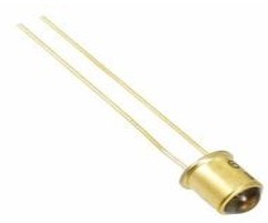 OP132 Hermetic Infrared Diode: Datasheet, Specifications and Applications
03 August 20211379
 megaAVR® 0-series 20MHz 8-bit MCU: Datasheet, UPDI, and Performance Deep Dive
06 February 202673
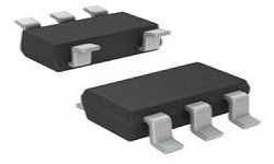 SN74LV1T34DCKR Shifter: Pinout, Applications and Datasheet
12 December 2023606
 STM32L010F4P6: Features, Applications, and Datasheet
29 November 20231648
 STM32MP157CAA3 Development: From Setup and Configuration to Advanced Features Implementation
07 June 2025929
 AD688BQ Voltage reference IC:Pinout, Specification, Datasheet
21 May 2021811
 3 simple steps to get Yageo CC0603KRX7R9BB103 models
16 August 2025141
 Semiconductor Industry Poised for $1 Trillion Growth Opportunity by 2030
20 November 20233791
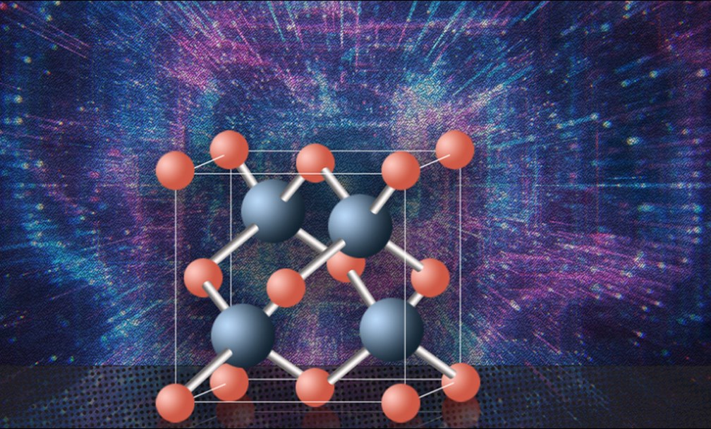 This New Material Promises to Be the Best Semiconductor
25 July 20222268
 TSMC's Global Distribution
25 March 20223353
 What Sensors are Used in Industrial Robots?
09 November 20215968
 What is 232\485\422 Communication? Common problems of Serial Communication
29 April 20222010
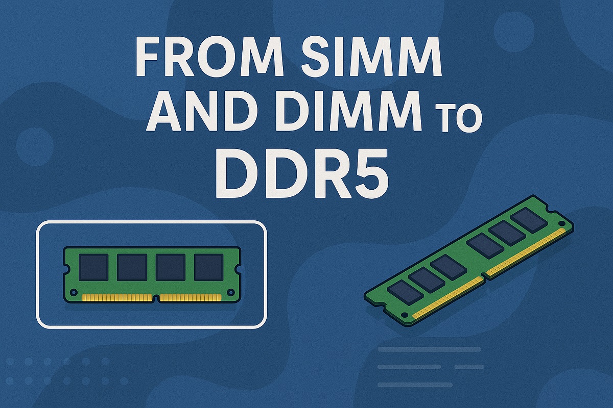 Understanding Computer Memory: From SIMM and DIMM to DDR5
23 May 202518929
 An Overview of Development Board
18 December 202514358
 Toggle Switches: Features, Types and Applications
23 January 202110636
Texas Instruments
In Stock: 4048
United States
China
Canada
Japan
Russia
Germany
United Kingdom
Singapore
Italy
Hong Kong(China)
Taiwan(China)
France
Korea
Mexico
Netherlands
Malaysia
Austria
Spain
Switzerland
Poland
Thailand
Vietnam
India
United Arab Emirates
Afghanistan
Åland Islands
Albania
Algeria
American Samoa
Andorra
Angola
Anguilla
Antigua & Barbuda
Argentina
Armenia
Aruba
Australia
Azerbaijan
Bahamas
Bahrain
Bangladesh
Barbados
Belarus
Belgium
Belize
Benin
Bermuda
Bhutan
Bolivia
Bonaire, Sint Eustatius and Saba
Bosnia & Herzegovina
Botswana
Brazil
British Indian Ocean Territory
British Virgin Islands
Brunei
Bulgaria
Burkina Faso
Burundi
Cabo Verde
Cambodia
Cameroon
Cayman Islands
Central African Republic
Chad
Chile
Christmas Island
Cocos (Keeling) Islands
Colombia
Comoros
Congo
Congo (DRC)
Cook Islands
Costa Rica
Côte d’Ivoire
Croatia
Cuba
Curaçao
Cyprus
Czechia
Denmark
Djibouti
Dominica
Dominican Republic
Ecuador
Egypt
El Salvador
Equatorial Guinea
Eritrea
Estonia
Eswatini
Ethiopia
Falkland Islands
Faroe Islands
Fiji
Finland
French Guiana
French Polynesia
Gabon
Gambia
Georgia
Ghana
Gibraltar
Greece
Greenland
Grenada
Guadeloupe
Guam
Guatemala
Guernsey
Guinea
Guinea-Bissau
Guyana
Haiti
Honduras
Hungary
Iceland
Indonesia
Iran
Iraq
Ireland
Isle of Man
Israel
Jamaica
Jersey
Jordan
Kazakhstan
Kenya
Kiribati
Kosovo
Kuwait
Kyrgyzstan
Laos
Latvia
Lebanon
Lesotho
Liberia
Libya
Liechtenstein
Lithuania
Luxembourg
Macao(China)
Madagascar
Malawi
Maldives
Mali
Malta
Marshall Islands
Martinique
Mauritania
Mauritius
Mayotte
Micronesia
Moldova
Monaco
Mongolia
Montenegro
Montserrat
Morocco
Mozambique
Myanmar
Namibia
Nauru
Nepal
New Caledonia
New Zealand
Nicaragua
Niger
Nigeria
Niue
Norfolk Island
North Korea
North Macedonia
Northern Mariana Islands
Norway
Oman
Pakistan
Palau
Palestinian Authority
Panama
Papua New Guinea
Paraguay
Peru
Philippines
Pitcairn Islands
Portugal
Puerto Rico
Qatar
Réunion
Romania
Rwanda
Samoa
San Marino
São Tomé & Príncipe
Saudi Arabia
Senegal
Serbia
Seychelles
Sierra Leone
Sint Maarten
Slovakia
Slovenia
Solomon Islands
Somalia
South Africa
South Sudan
Sri Lanka
St Helena, Ascension, Tristan da Cunha
St. Barthélemy
St. Kitts & Nevis
St. Lucia
St. Martin
St. Pierre & Miquelon
St. Vincent & Grenadines
Sudan
Suriname
Svalbard & Jan Mayen
Sweden
Syria
Tajikistan
Tanzania
Timor-Leste
Togo
Tokelau
Tonga
Trinidad & Tobago
Tunisia
Turkey
Turkmenistan
Turks & Caicos Islands
Tuvalu
U.S. Outlying Islands
U.S. Virgin Islands
Uganda
Ukraine
Uruguay
Uzbekistan
Vanuatu
Vatican City
Venezuela
Wallis & Futuna
Yemen
Zambia
Zimbabwe
![SN74LVC4245APWR]() SN74LVC4245APWR
SN74LVC4245APWRTexas Instruments
![PCA9306DCUR]() PCA9306DCUR
PCA9306DCURTexas Instruments
![PCA9306DCTR]() PCA9306DCTR
PCA9306DCTRTexas Instruments
![TCA9803DGKR]() TCA9803DGKR
TCA9803DGKRTexas Instruments
![SN74AVC4T245RGYR]() SN74AVC4T245RGYR
SN74AVC4T245RGYRTexas Instruments
![SN74AVC4T245PWR]() SN74AVC4T245PWR
SN74AVC4T245PWRTexas Instruments
![SN74LVC2T45DCUR]() SN74LVC2T45DCUR
SN74LVC2T45DCURTexas Instruments
![SN74LVC2T45DCTR]() SN74LVC2T45DCTR
SN74LVC2T45DCTRTexas Instruments
![TXS0102DCUR]() TXS0102DCUR
TXS0102DCURTexas Instruments
![SN74AVC8T245RHLR]() SN74AVC8T245RHLR
SN74AVC8T245RHLRTexas Instruments


