
 Product
 Brand
Brand Articles
 Tools
Tools
STM32MP157CAA3 Development: From Setup and Configuration to Advanced Features Implementation


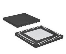
ARM® Cortex®-A7 Microprocessor STM32MP1 Series 448-LFBGA
Master STM32MP157CAA3 development with guides on setup, tools like STM32CubeMX, and advanced features for efficient embedded system projects.
Product Introduction
The STM32MP157CAA3 plays a vital role in modern embedded systems. Its dual-core architecture and advanced features make it a preferred choice for applications requiring high performance and flexibility. Understanding its development process ensures you can harness its full potential.
Mastering this process offers several benefits:
Achieve faster time-to-market with streamlined software porting.
Enhance performance using versatile peripherals.
Ensure compliance with certified security services.
Access a broad third-party ecosystem for additional tools and resources.
A well-rounded guide can help you unlock these advantages and create robust solutions for your projects.
Overview of STM32MP157CAA3 and STM32MP1 Series
Features and specifications of STM32MP157CAA3
The STM32MP157CAA3 stands out in the stm32 series of microcontrollers due to its powerful features and versatility. It combines dual Cortex-A7 cores running at up to 800 MHz with a Cortex-M4 core operating at 209 MHz. This heterogeneous architecture enables efficient multitasking and real-time processing.
Here’s a quick look at its key specifications:
| Feature | Specification |
|---|---|
| Core Architecture | Dual Cortex-A7 cores up to 800 MHz |
| Additional Core | Cortex-M4 core at 209 MHz |
| GPU | 3D GPU |
| Display Interface | DSI display interface |
| Communication Protocol | CAN FD |
| Energy Optimization | STM32MP13x product line |
| Heterogeneous Processing | STM32MP15x product line |
| Temperature Range | Extended junction temperature up to 125° |
| Application Areas | Industry 4.0, smart city, smart home |
These features make the STM32MP157CAA3 ideal for applications requiring high performance, such as the osd32mp1-red development platform.
Architecture of STM32 Arm Cortex MCUs
The stm32 arm cortex mcus are designed for high efficiency and performance. For example, the STM32L432KC uses a multilayer AHB Bus Matrix. This matrix includes five masters, such as the Cortex-M4 core and DMA units, and seven slaves, including internal Flash and SRAM.
Key architectural highlights include:
Concurrent communication between multiple masters and slaves for better performance.
The ART Accelerator™, which optimizes memory access and achieves near 100 DMIPS performance at 80 MHz.
This architecture ensures that devices like the osd32mp15x can handle complex tasks with ease.
Development tools and STM32MP1 ecosystem
The stm32mp1 ecosystem simplifies development with its comprehensive toolset. It includes an open-source Linux distribution with Android support, making it easier to port application software. Tools like STM32CubeMX and STM32CubeProgrammer allow you to configure and debug the DRAM subsystem efficiently.
Additionally, the ecosystem benefits from third-party partners offering system-on-modules, secure software, and training services. These resources enhance platforms like the osd32mp15x and provide developers with everything needed to succeed.
Getting Started with STM32MP157CAA3 Development
Hardware and software prerequisites
Before diving into STM32MP157CAA3 development, you need to prepare the essential hardware and software. This ensures a smooth start and avoids common pitfalls.
Hardware Requirements:
STM32MP157CAA3 Development Board: Choose a reliable platform like the osd32mp15x for testing and prototyping.
Power Supply: Ensure a stable power source for your board.
USB Cable: Use it to connect the board to your computer for programming and debugging.
Debugging Tools: Consider tools like ST-LINK or JTAG for advanced debugging.
Software Requirements:
Operating System: A Linux-based OS is recommended for STM32MP1 development. Ubuntu is a popular choice.
Development Tools: Install STM32CubeMX, STM32CubeIDE, and STM32CubeProgrammer. These tools simplify configuration, coding, and debugging.
Compiler: Use GCC for compiling initialization C code and other projects.
Tip: Double-check your hardware connections and software installations before proceeding. This avoids troubleshooting delays during the setup phase.
Installing STM32CubeMX and other tools
STM32CubeMX is a cornerstone of STM32MP157CAA3 development. It simplifies peripheral configuration and generates initialization C code for your projects. Follow these steps to install STM32CubeMX and other tools:
Download STM32CubeMX: Visit STMicroelectronics' official website and download the latest version of STM32CubeMX.
Install STM32CubeMX: Run the installer and follow the on-screen instructions. Ensure you select the correct installation directory.
Install STM32CubeIDE: This Eclipse-based IDE supports STM32MP1 development. It integrates debugging and code editing features.
Set Up STM32CubeProgrammer: Use this tool for flashing firmware onto the osd32mp15x board. It also helps with memory management.
Verify Installation: Open each tool to confirm successful installation. Check for updates to ensure compatibility with your STM32MP157CAA3 board.
Note: Users have reported challenges with importing U-Boot ELF files into STM32CubeIDE during board bring-up. Familiarize yourself with the STM32 MPU forum for troubleshooting tips.
Initial setup and configuration of STM32MP157CAA3
Once you have the hardware and tools ready, you can begin the initial setup of your STM32MP157CAA3 board. This step involves configuring the board and preparing it for development.
Step-by-Step Guide:
Connect the Board: Use a USB cable to connect the osd32mp15x board to your computer. Ensure the power supply is stable.
Launch STM32CubeMX: Open STM32CubeMX and create a new project. Select STM32MP157CAA3 as your target device.
Configure Peripherals: Use the graphical interface to enable peripherals like GPIO, UART, and SPI. This generates initialization C code for your project.
Set Clock Settings: Configure the clock tree to optimize performance and power consumption.
Export Project: Save the configuration and export the project to STM32CubeIDE for further development.
Flash Firmware: Use STM32CubeProgrammer to flash the firmware onto the osd32mp15x board. Verify the flashing process to ensure proper functionality.
Tip: Start with a minimal configuration to test basic functionality. Gradually add peripherals and features as your project progresses.
By following this guide, you can streamline the process of getting started with STM32MP157CAA3 development. This ensures your board is ready for advanced applications and testing.
STM32MP1 CubeMX Tutorial and Essential Configurations
Clock settings and power management
Configuring the clock settings and power management is a critical step in your stm32mp1 development journey. Proper clock settings ensure that your osd32mp15x board operates efficiently, while power management optimizes energy consumption for your project.
To begin, open the cubemx software tool and navigate to the "Clock Configuration" tab. Here, you can set the frequencies for the Cortex-A7 and Cortex-M4 cores. Adjust the PLL (Phase-Locked Loop) settings to match your application's performance requirements. For example, you might configure the Cortex-A7 cores to run at 800 MHz for high-performance tasks.
Power management involves enabling low-power modes and configuring voltage scaling. In the "Power Configuration" tab, you can activate features like Standby and Sleep modes. These modes reduce power consumption when the system is idle. Additionally, you can use the STM32CubeMX tool to enable Dynamic Voltage Scaling (DVS), which adjusts the voltage based on the workload.
Tip: Always test your clock and power settings on the osd32mp15x board to ensure stability and efficiency.
Device tree and memory configurations
The device tree and memory configurations define how your stm32mp1 hardware interacts with the software. These settings are essential for ensuring that your project runs smoothly on the osd32mp15x platform.
In STM32MP1 CubeMX, the device tree configuration involves defining hardware components like GPIOs, UARTs, and memory interfaces. Navigate to the "Device Tree Configuration" tab and enable the peripherals required for your project. For example, you might enable the DDR controller for external memory access.
Memory configuration focuses on setting up the DDR (Double Data Rate) memory. Use the DDR Test Suite to validate the STM32MPU-DRAM connection. This suite provides methods for running tests via JTAG or STM32CubeProgrammer CLI. Additionally, refer to the UM1718 documentation for guidance on generating device tree files for the DDR controller.
Here’s a summary of validation tools and resources:
| Source | Description |
|---|---|
| DDR Test Suite | Provides instructions for validating the STM32MPU-DRAM connection, including methods for running tests via JTAG or STM32CubeProgrammer CLI. |
| UM1718 | Documentation on device tree file generation for configuring the STM32MPU DDR controller, including instructions for running DDR tests. |
| AN5168 | Application note detailing configuration parameters for the STM32MP1 family DDR controller. |
Note: Accurate device tree and memory configurations prevent runtime errors and improve system performance.
Building and deploying a minimal project
Once you’ve completed the cubemx configuration, you can build and deploy a minimal project to test your stm32mp1 setup. This step ensures that your osd32mp15x board is ready for more complex applications.
Generate Code: In STM32CubeMX, click the "Generate Code" button. This action creates the cubemx project files, including initialization code for your peripherals.
Open in STM32CubeIDE: Import the generated project into STM32CubeIDE. Verify that all files are correctly loaded.
Write Application Code: Add a simple application to test basic functionality. For example, you can toggle an LED or send data over UART.
Build the Project: Compile the project using the STM32CubeIDE build tools. Ensure there are no errors or warnings.
Deploy to the Board: Use STM32CubeProgrammer to flash the firmware onto the osd32mp15x board. Connect the board to your computer via USB and follow the on-screen instructions.
Test the Application: Run the application on the board and verify its functionality. Check the LED or UART output to confirm that the project works as expected.
Pro Tip: Start with a minimal project to familiarize yourself with the tools and workflow. Gradually add features as you gain confidence.
By following this stm32mp1 cubemx tutorial, you can streamline the process of generating code using cubemx and deploying it to your osd32mp15x board. This approach ensures a solid foundation for your development projects.
Practical Development with STM32MP157CAA3
Flashing firmware and debugging
Flashing firmware onto the STM32MP157CAA3 is a crucial step in your project. It allows you to test and validate your code on the osd32mp15x board. Start by connecting the board to your computer using a USB cable. Open STM32CubeProgrammer, select the correct target device, and load the firmware file. Follow the on-screen instructions to flash the firmware.
Debugging ensures that your project runs as expected. Use STM32CubeIDE for debugging. Connect the osd32mp15x board to your computer and launch the debugger. Set breakpoints in your code to monitor execution. Use the debugging tools to inspect variables, check memory usage, and identify errors. This process helps you refine your configuration and improve your project’s performance.
Tip: Always verify the firmware after flashing to ensure it was uploaded correctly.
Testing applications on STM32MP1
Testing your applications on the STM32MP1 platform ensures they function as intended. Begin by deploying your application to the osd32mp15x board. Use STM32CubeProgrammer to load the application binary. Once deployed, run the application and monitor its behavior.
For example, if your project involves toggling an LED, observe the LED’s response. If it doesn’t work as expected, revisit your configuration and code. Use the debugging tools to identify and fix issues. Testing also involves checking the application’s performance under different conditions. This step ensures your project meets its requirements.
Pro Tip: Test each feature of your project individually before integrating them. This approach simplifies troubleshooting.
Exploring advanced features and use cases
The STM32MP157CAA3 offers advanced features that enhance your project. These include functional safety, secure boot, and hardware encryption. To explore these features, refer to the detailed documentation available for the STM32MP1 series.
| Document Type | Description |
|---|---|
| User Manual | Information on safety manuals and self-test libraries. |
| Security Bulletin | Details on EUCLEAK protection and physical attack prevention. |
| Product Presentation | Overview of functional safety packages and development tools. |
| Application Note | Guidelines for oscillator design, audio generation, and more. |
| Reference Manual | Advanced details on the STM32MP157 microprocessor. |
These resources provide valuable insights into advanced configurations and innovative use cases. For instance, you can implement secure boot to protect your project from unauthorized access. You can also use hardware encryption to enhance data security.
Note: Always test advanced features on the osd32mp15x board to ensure compatibility with your project.
Resources for STM32MP157CAA3 Development
Official documentation and guides
Accessing official documentation is essential for mastering STM32MP157CAA3. These guides provide detailed insights into configuration, tools, and project workflows. You can explore the STM32MP157 documentation, which includes user manuals, reference guides, and application notes. These resources cover everything from basic setup to advanced configurations.
Here are some key resources to get you started:
These guides ensure you have a solid foundation for your project. For example, the cubemx user manual explains how to configure peripherals and generate initialization code.
Tip: Bookmark these resources for quick access during your development journey.
Community forums and GitHub repositories
Community forums and GitHub repositories are invaluable for troubleshooting and collaboration. The STM32 MCU Community is a vibrant platform where you can ask questions, share experiences, and find solutions to common challenges.
GitHub repositories host open-source projects, libraries, and tutorials for STM32MP1. These repositories often include sample code and configuration files that you can adapt for your project. Exploring these resources can save you time and effort.
Some useful links include:
Pro Tip: Engage with the community to stay updated on the latest tools and techniques.
Training materials and advanced tutorials
Training materials and tutorials help you deepen your understanding of STM32MP1. STMicroelectronics and its partners offer webinars, video tutorials, and hands-on workshops. These resources cover topics like advanced configuration, secure boot, and hardware encryption.
For example, you can find training on development boards and hardware tools from partners. These sessions often include practical exercises that enhance your skills. Additionally, advanced tutorials guide you through complex use cases, such as implementing functional safety or optimizing power management.
Explore these resources to expand your expertise:
Note: Regularly update your knowledge by attending training sessions and reviewing new tutorials.
Mastering STM32MP157CAA3 development begins with a solid foundation. You start by preparing the hardware and software, installing essential tools like STM32CubeMX, and configuring the board for your project. Each step builds your confidence and ensures your setup is ready for advanced applications.
Leveraging tools and resources accelerates your progress. The STM32 ecosystem offers fast time-to-market, open-source Linux support, and Android compatibility. STM32Cube firmware and embedded libraries simplify your workflow, making it easier to port software and optimize your project.
Exploring advanced features unlocks the full potential of STM32MP157CAA3. Functional safety, secure boot, and hardware encryption enhance your project’s capabilities. Dive into these features to create innovative solutions that stand out in embedded systems.
Tip: Stay curious and keep experimenting. Each project is an opportunity to learn and grow as a developer.
FAQ
What makes the STM32MP157CAA3 suitable for your project?
The STM32MP157CAA3 offers dual-core processing, a Cortex-M4 core, and advanced peripherals. These features make it ideal for multitasking and real-time applications. Its compatibility with the STM32MP1 ecosystem simplifies development, ensuring your project benefits from robust tools and resources.
How do you debug your project on the STM32MP157CAA3?
You can debug your project using STM32CubeIDE. Connect your board to the computer, set breakpoints, and monitor code execution. This process helps you identify and fix issues efficiently, ensuring your project runs smoothly.
Can you use STM32MP157CAA3 for industrial projects?
Yes, the STM32MP157CAA3 supports industrial applications like Industry 4.0 and smart city solutions. Its extended temperature range and secure boot features make it reliable for demanding environments, ensuring your project meets industrial standards.
What tools simplify STM32MP157CAA3 development?
Tools like STM32CubeMX, STM32CubeIDE, and STM32CubeProgrammer simplify development. They help you configure peripherals, write code, and flash firmware. These tools streamline your workflow, saving time and improving your project’s efficiency.
How do you optimize power consumption in your project?
Use STM32CubeMX to configure low-power modes and dynamic voltage scaling. These settings reduce energy usage during idle periods. Testing these configurations on your board ensures your project achieves optimal power efficiency.
Specifications
- TypeParameter
- Factory Lead Time10 Weeks
- Package / Case
refers to the protective housing that encases an electronic component, providing mechanical support, electrical connections, and thermal management.
448-LFBGA - Operating Temperature
The operating temperature is the range of ambient temperature within which a power supply, or any other electrical equipment, operate in. This ranges from a minimum operating temperature, to a peak or maximum operating temperature, outside which, the power supply may fail.
-40°C~125°C TA - Packaging
Semiconductor package is a carrier / shell used to contain and cover one or more semiconductor components or integrated circuits. The material of the shell can be metal, plastic, glass or ceramic.
Tray - Series
In electronic components, the "Series" refers to a group of products that share similar characteristics, designs, or functionalities, often produced by the same manufacturer. These components within a series typically have common specifications but may vary in terms of voltage, power, or packaging to meet different application needs. The series name helps identify and differentiate between various product lines within a manufacturer's catalog.
STM32MP1 - Part Status
Parts can have many statuses as they progress through the configuration, analysis, review, and approval stages.
Active - Moisture Sensitivity Level (MSL)
Moisture Sensitivity Level (MSL) is a standardized rating that indicates the susceptibility of electronic components, particularly semiconductors, to moisture-induced damage during storage and the soldering process, defining the allowable exposure time to ambient conditions before they require special handling or baking to prevent failures
3 (168 Hours) - Reach Compliance Code
Reach Compliance Code refers to a designation indicating that electronic components meet the requirements set by the Registration, Evaluation, Authorization, and Restriction of Chemicals (REACH) regulation in the European Union. It signifies that the manufacturer has assessed and managed the chemical substances within the components to ensure safety and environmental protection. This code is vital for compliance with regulations aimed at minimizing risks associated with hazardous substances in electronic products.
compliant - Speed
In electronic components, "Speed" typically refers to the rate at which data can be processed or transferred within the component. It is a measure of how quickly the component can perform its functions, such as executing instructions or transmitting signals. Speed is often specified in terms of frequency, such as clock speed in processors or data transfer rate in memory modules. Higher speed components can perform tasks more quickly, leading to improved overall performance in electronic devices. It is an important parameter to consider when designing or selecting electronic components for specific applications.
209MHz, 650MHz - Core Processor
The term "Core Processor" typically refers to the central processing unit (CPU) of a computer or electronic device. It is the primary component responsible for executing instructions, performing calculations, and managing data within the system. The core processor is often considered the brain of the device, as it controls the overall operation and functionality. It is crucial for determining the speed and performance capabilities of the device, as well as its ability to handle various tasks and applications efficiently. In modern devices, core processors can have multiple cores, allowing for parallel processing and improved multitasking capabilities.
ARM® Cortex®-A7 - Voltage - I/O
Voltage - I/O is a parameter that refers to the voltage levels at the input and output pins of an electronic component, such as an integrated circuit or a semiconductor device. It specifies the range of voltages that the component can accept at its input pins and the voltages it will output at its output pins under normal operating conditions. This parameter is crucial for ensuring proper functionality and compatibility with other components in a circuit. It helps designers determine the appropriate voltage levels to use when interfacing with the component to prevent damage and ensure reliable operation.
2.5V 3.3V - Ethernet
Ethernet is a widely used networking technology that allows devices to communicate with each other over a local area network (LAN). It is a set of standards that define how data is transmitted over a physical medium, typically using twisted-pair cables or fiber optics. Ethernet specifies the protocols for data transmission, addressing, and error detection, ensuring reliable and efficient communication between devices. It is commonly used in homes, businesses, and data centers to connect computers, printers, routers, and other networked devices. Ethernet has evolved over the years to support faster speeds and improved performance, making it a fundamental component of modern networking infrastructure.
10/100Mbps (1) - Number of Cores/Bus Width2 Core 32-Bit
- Graphics Acceleration
Graphics accelerators speed up the displaying of images on the monitor making it possible to achieve effects not otherwise possible - for example, the presentation of very large images or of interactive games in which images need to change quickly in response to user input.
Yes - RAM Controllers
RAM controllers are electronic components responsible for managing the flow of data to and from random access memory (RAM) in a computer system. They control the timing and data transfer between the CPU and RAM, ensuring efficient communication and data access. RAM controllers play a crucial role in determining the speed and performance of a computer system by optimizing memory access and utilization. These controllers are typically integrated into the motherboard or processor and are essential for the overall functioning of the system's memory subsystem.
LPDDR2, LPDDR3, DDR3, DDR3L - USB
USB stands for Universal Serial Bus, which is a common interface used for connecting various electronic devices to a computer or other host device. It allows for the transfer of data, power, and communication between devices. USB ports are found on a wide range of devices such as computers, smartphones, printers, cameras, and more. The USB standard has evolved over the years to include different versions with varying data transfer speeds and power delivery capabilities. Overall, USB has become a widely adopted and versatile standard for connecting and interacting with electronic components.
USB 2.0 (2), USB 2.0 OTG+ PHY (3) - Additional Interfaces
Additional Interfaces in electronic components refer to the extra connections or ports that allow the component to interact with other devices or systems. These interfaces can include various types of communication protocols such as USB, HDMI, Ethernet, or wireless connections like Bluetooth or Wi-Fi. The presence of additional interfaces expands the functionality and versatility of the electronic component, enabling it to send and receive data, signals, or power to and from external devices. Designers and users can utilize these interfaces to enhance the capabilities and connectivity of the electronic component within a larger system or network.
CAN, Ethernet, I2C, MMC/SD/SDIO, SPDIF, SPI, UART, USB - Co-Processors/DSP
Co-processors and Digital Signal Processors (DSPs) are specialized electronic components designed to handle specific types of computation tasks more efficiently than a general-purpose CPU. Co-processors assist the main processor by executing complex mathematical calculations or processing data in parallel, often enhancing performance for applications like graphics rendering or scientific computations. DSPs, on the other hand, are optimized for processing digital signals in real-time, making them ideal for applications in audio processing, telecommunications, and image processing. Together, these components enable more efficient data handling and improved system performance in various electronic devices.
ARM® Cortex®-M4 - Security Features
Security features include authentication of both users and devices as well as authorization of access to different resources such as IoT data, DM, and other system features.
ARM TZ - Display & Interface Controllers
A unit in a computer system consisting of channels and associated control circuitry that connect a number of visual display units with a central processor.
HDMI, LCD - RoHS Status
RoHS means “Restriction of Certain Hazardous Substances” in the “Hazardous Substances Directive” in electrical and electronic equipment.
RoHS Compliant
Datasheet PDF
- Datasheets :
 ATMEGA162V Microcontroller: Pinout, Equivalent and Datasheet
18 April 20221112
 STM32G070CBT6: Overview, Features, and Datasheet
11 December 20233213
 Top-Rated Suppliers of ADIS16209CCCZ Sensors
07 June 2025148
 KSZ8895MQXI Ethernet Switch SPI Interface 128-PQFP: Datasheet, Pinout, and equivalent
11 February 20222146
 ATTINY45 Microcontroller: Pinout, Specifications and Datasheet
19 October 20216422
 LTC6811 12-Cell Battery Monitor: Solving isoSPI Communication and PEC Errors
10 March 2026759
![TLC555CP Timer[FAQ+Video]: Datasheet, Alternatives, Pinout and LMC555CN vs TLC555CP](https://res.utmel.com/Images/Article/dc1fdaf9-08c0-4928-94b3-9036f30eeaa1.jpg) TLC555CP Timer[FAQ+Video]: Datasheet, Alternatives, Pinout and LMC555CN vs TLC555CP
TLC555CP Timer[FAQ+Video]: Datasheet, Alternatives, Pinout and LMC555CN vs TLC555CP14 April 20224988
 MAX3600A Laser Driver: Datasheet, Pinout, Circuit
31 August 2021386
 What are Shunts?
07 December 20207794
 Bluetooth Explained: Characteristics and Applications
02 June 202121196
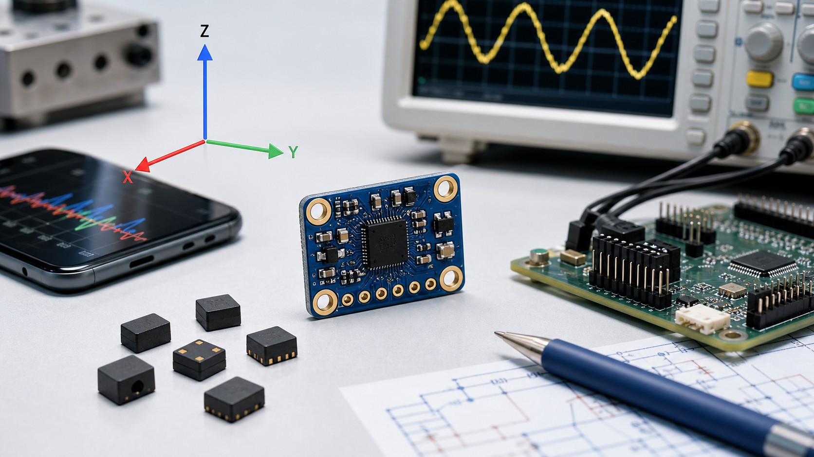 Accelerometer Sensors Guide: Working Principle, Circuit Design, Specifications, and Applications
25 June 2026254
 Msemitek Authorized Distributor | UTMEL Electronics
21 November 20233892
 What is a Monostable Multivibrator?
16 January 20216867
 2026 Memory: Strategic Sourcing Tactics for DRAM & NAND Price Hikes
07 July 2026142
 What is a Capacitive Sensor?
31 October 202510888
 All You Need to Know about Wireless Access Point
26 October 20214843
STMicroelectronics
In Stock: 613
United States
China
Canada
Japan
Russia
Germany
United Kingdom
Singapore
Italy
Hong Kong(China)
Taiwan(China)
France
Korea
Mexico
Netherlands
Malaysia
Austria
Spain
Switzerland
Poland
Thailand
Vietnam
India
United Arab Emirates
Afghanistan
Åland Islands
Albania
Algeria
American Samoa
Andorra
Angola
Anguilla
Antigua & Barbuda
Argentina
Armenia
Aruba
Australia
Azerbaijan
Bahamas
Bahrain
Bangladesh
Barbados
Belarus
Belgium
Belize
Benin
Bermuda
Bhutan
Bolivia
Bonaire, Sint Eustatius and Saba
Bosnia & Herzegovina
Botswana
Brazil
British Indian Ocean Territory
British Virgin Islands
Brunei
Bulgaria
Burkina Faso
Burundi
Cabo Verde
Cambodia
Cameroon
Cayman Islands
Central African Republic
Chad
Chile
Christmas Island
Cocos (Keeling) Islands
Colombia
Comoros
Congo
Congo (DRC)
Cook Islands
Costa Rica
Côte d’Ivoire
Croatia
Cuba
Curaçao
Cyprus
Czechia
Denmark
Djibouti
Dominica
Dominican Republic
Ecuador
Egypt
El Salvador
Equatorial Guinea
Eritrea
Estonia
Eswatini
Ethiopia
Falkland Islands
Faroe Islands
Fiji
Finland
French Guiana
French Polynesia
Gabon
Gambia
Georgia
Ghana
Gibraltar
Greece
Greenland
Grenada
Guadeloupe
Guam
Guatemala
Guernsey
Guinea
Guinea-Bissau
Guyana
Haiti
Honduras
Hungary
Iceland
Indonesia
Iran
Iraq
Ireland
Isle of Man
Israel
Jamaica
Jersey
Jordan
Kazakhstan
Kenya
Kiribati
Kosovo
Kuwait
Kyrgyzstan
Laos
Latvia
Lebanon
Lesotho
Liberia
Libya
Liechtenstein
Lithuania
Luxembourg
Macao(China)
Madagascar
Malawi
Maldives
Mali
Malta
Marshall Islands
Martinique
Mauritania
Mauritius
Mayotte
Micronesia
Moldova
Monaco
Mongolia
Montenegro
Montserrat
Morocco
Mozambique
Myanmar
Namibia
Nauru
Nepal
New Caledonia
New Zealand
Nicaragua
Niger
Nigeria
Niue
Norfolk Island
North Korea
North Macedonia
Northern Mariana Islands
Norway
Oman
Pakistan
Palau
Palestinian Authority
Panama
Papua New Guinea
Paraguay
Peru
Philippines
Pitcairn Islands
Portugal
Puerto Rico
Qatar
Réunion
Romania
Rwanda
Samoa
San Marino
São Tomé & Príncipe
Saudi Arabia
Senegal
Serbia
Seychelles
Sierra Leone
Sint Maarten
Slovakia
Slovenia
Solomon Islands
Somalia
South Africa
South Sudan
Sri Lanka
St Helena, Ascension, Tristan da Cunha
St. Barthélemy
St. Kitts & Nevis
St. Lucia
St. Martin
St. Pierre & Miquelon
St. Vincent & Grenadines
Sudan
Suriname
Svalbard & Jan Mayen
Sweden
Syria
Tajikistan
Tanzania
Timor-Leste
Togo
Tokelau
Tonga
Trinidad & Tobago
Tunisia
Turkey
Turkmenistan
Turks & Caicos Islands
Tuvalu
U.S. Outlying Islands
U.S. Virgin Islands
Uganda
Ukraine
Uruguay
Uzbekistan
Vanuatu
Vatican City
Venezuela
Wallis & Futuna
Yemen
Zambia
Zimbabwe
![SPEAR320-2]() SPEAR320-2
SPEAR320-2STMicroelectronics
![STA1080EOA]() STA1080EOA
STA1080EOASTMicroelectronics
![SPEAR300-2]() SPEAR300-2
SPEAR300-2STMicroelectronics
![SPEAR310-2]() SPEAR310-2
SPEAR310-2STMicroelectronics
![SPEAR600-2]() SPEAR600-2
SPEAR600-2STMicroelectronics
![STA1078EOA]() STA1078EOA
STA1078EOASTMicroelectronics
![STA1085EOATR]() STA1085EOATR
STA1085EOATRSTMicroelectronics
![SPEAR320S-2]() SPEAR320S-2
SPEAR320S-2STMicroelectronics
![STA1085EOA]() STA1085EOA
STA1085EOASTMicroelectronics
![STA1079EOA]() STA1079EOA
STA1079EOASTMicroelectronics


